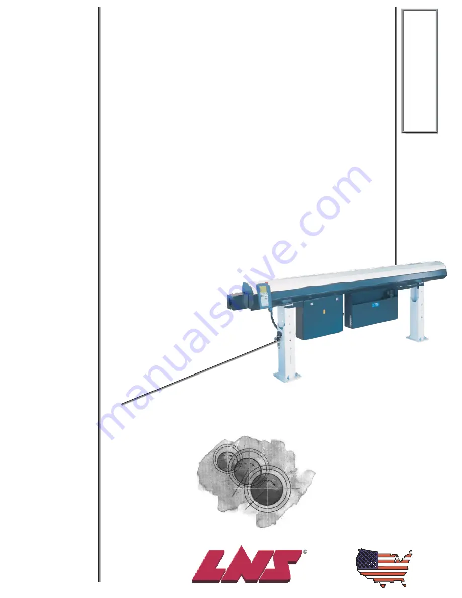
background image

MADE IN USA

Serial

Nr

:

LNS

America,

Inc.

USA

4621

East

Tech

Drive

Cincinnati,

Ohio

45245

Phone#

513.528.5674

http://www

.LNSAmerica.com

Main

fax#

513.528.5733

Service

fax#

513.528.8320

220

220

220

Hydrobar

Express

Hydrobar

Express

Hydrobar

Express

TROUBLESHOOTING
AND

SPARE

PARTS

MANUAL

TROUBLESHOOTING
AND

SPARE

PARTS

MANUAL

TROUBLESHOOTING
AND

SPARE

PARTS

MANUAL

Summary of Contents for Hydrobar Express 220

Page 1: ...io 45245 Phone 513 528 5674 http www LNSAmerica com Main fax 513 528 5733 Service fax 513 528 8320 220 220 220 Hydrobar Express Hydrobar Express Hydrobar Express TROUBLESHOOTING AND SPARE PARTS MANUAL TROUBLESHOOTING AND SPARE PARTS MANUAL TROUBLESHOOTING AND SPARE PARTS MANUAL ...

Page 2: ...3 Pusher Lost the Bar Stock During its Return to Home Position 1 24 Bar Stock Not Extracted from the Collet 1 25 Vise Coupling Device Malfunction 1 26 Switch SQ4 Signal Missing 1 28 Bar Stock Loading Error 1 29 Bar Loading Error 1 30 Bar Remnant Too Long 1 31 Bar Stock Moving Backwards during Headstock Reverse with Collet Open 1 32 Bar Stock Moving Forward during Headstock Reverse with Collet Open...

Page 3: ... Update 4 16 Restore PLC Program from Memory Card to PLC v1 17a 4 16 PLC Fault v2 08 4 20 Software Update v2 08 4 23 Chapter 5 5 1 Preventative Maintenance 5 1 Daily Maintenance 5 2 Weekly Maintenance 5 2 Monthly Maintenance 5 2 Annual Maintenance 5 3 Chapter 6 6 1 Spare Parts 6 1 Recommended Spare Parts List 6 2 Collet Reference Chart 6 3 Guiding Channel Reference Chart 6 4 Parts Order Form 6 5 E...

Page 4: ...enerated on the remote control station Also provided are some possible causes as to why the error has occurred This troubleshooting guide discusses every alarm that the bar feed may generate In conjunction with each alarm will be a brief description of what the alarm is and a few tips and procedures of how to correct the problem A Figure 1 1 Remote control station ...

Page 5: ... disconnect switch SP1 Pneumatic pressure switch SP2 Hydraulic pressure switch SQ1 Positioning stopper proximity switch SQ2 Bar magazine diameter counting monitor SQ3 Opening guiding channel control switch SQ4 Closing guiding channel control switch SQ5 Remnant check SQ6 Control switch mobile vise in forward position SQ7 Control switch pusher in rear park position SQ8 Front rest opening monitor SQ9...

Page 6: ...hes once the bar feed sends an alarm to the machine the machine will in return send an emergency stop alarm to the bar feed which overrides any bar feed alarms Once the bar feed alarm is overridden the only way to pinpoint the original bar feed alarm is to enter into the alarm history This menu is located HELP menu to locate the alarm history follow the steps below Step 1 Press the HELP key on the...

Page 7: ...anual Solution Press the HELP key on the remote control station Press the F4 key Page Down icon twice Case Input Remote Pendant Solution 1 Bit 0 0 MODULE 0 76543210 0 Verify that the 1 0 connector is plugged into the PLC correctly Verify that the circuitry is wired correctly to the electrical diagram on page 4 17 in the Express 220 Instruction Manual 2 Bit 0 1 MODULE 0 76543210 1 Alarm needs to be...

Page 8: ...ush button is pressed in Solution Press the HELP key on the remote control station Press the F4 Page Down icon twice Case Input Remote Pendant Solution 1 Bit 3 1 MODULE 0 76543210 1000 Alarm needs to be cleared Press the STOP key on the remote control station to clear the message and reset the alarm 2 Bit 3 0 MODULE 0 76543210 0 Reset the E stop push button on the lathe For case 2 after the soluti...

Page 9: ...ol station is pressed in Solution Press the HELP key on the remote control station Press the F4 Page Down icon twice Case Input Remote Pendant Solution 1 Bit 2 1 MODULE 0 76543210 100 Alarm needs to be cleared Press the STOP key on the remote control station to clear the message and reset the alarm 2 Bit 2 0 MODULE 0 76543210 0 Reset the E stop push button on the remote control station For case 2 ...

Page 10: ... until the chuck is open Solution Press the HELP key on the remote control station Press the F4 key Page Down icon twice Case Input Remote Pendant Solution 1 Bit 6 1 MODULE 0 76543210 1000000 Alarm needs to be cleared Press the STOP key on the remote control station to clear the message and reset the alarm Check the oil level indicator on the side of the hydraulic tank and make sure there is suffi...

Page 11: ...ch Solution Press the HELP key on the remote control station Press the F4 Page Down icon twice Case Input Remote Pendant Solution 1 Bit 5 1 MODULE 0 76543210 100000 Alarm needs to be cleared Press the STOP key on the remote control station to clear the message and reset the alarm Raise the incoming air pressure on the air regulator to recommended 75 psi and no higher than 90 psi Flip the toggle sw...

Page 12: ... operator or service technician needs to perform any work inside the unit Solution Press the HELP key on the remote control station Press the F4 key Page Down icon twice Case Input Remote Pendant Solution 1 Bit 4 1 MODULE 0 76543210 10000 Close the main access cover 2 Bit 4 0 MODULE 0 76543210 0 Alarm needs to be cleared Press the STOP key on the remote control station to clear the message and res...

Page 13: ...retracted for spindle liner changeover Solution Press the HELP key on the remote control station Press the F4 key Page Down icon twice Case Input Remote Pendant Solution 1 Bit 1 1 MODULE 0 76543210 10 Put the bar feeder back in its working position and lock the latches 2 Bit 1 0 MODULE 0 76543210 0 Alarm needs to be cleared Press the STOP key on the remote control station to clear the message and ...

Page 14: ...n twice Case Input Remote Pendant Solution Check to see if there is a mechanical obstruction preventing the measuring stop from rising up Make sure that the SQ1 switch is adjusted to within a sensing distance of 0 5mm 1mm from the measuring stop 1 Bit 7 1 MODULE 0 76543210 10000000 If the input still does not turn on the problem can be isolated to a defective switch or defective cable Replace the ...

Page 15: ...wice Case Input Remote Pendant Solution Check to see if there is a mechanical obstruction preventing the measuring stop from rising up Make sure that the SQ1 switch is adjusted to within a sensing distance of 0 5mm 1mm from the measuring stop Check that the air flow restrictor has not cut off the air supply to the cylinder 1 Bit 7 0 MODULE 0 76543210 0 If the input still does not turn on the probl...

Page 16: ...remote control station Press the F4 key Page Down icon twice Case Input Remote Pendant Solution Check to see if there is a mechanical obstruction preventing the measuring stop from dropping Make sure that the SQ1 switch is adjusted to within a sensing distance of 0 5mm 1mm from the measuring stop 1 Bit 7 1 MODULE 0 76543210 10000000 Check the wiring of switch SQ1 2 Bit 7 0 MODULE 0 76543210 0 Alar...

Page 17: ...P key on the remote control station Press the F4 key Page Down icon twice Case Input Remote Pendant Solution 1 Bit 1 1 MODULE 1 76543210 10 Check to see if a mechanical obstruction is preventing the channel from closing Check the functionality of the SQ3 switch The switch may be sticking and needs to be replaced 2 Bit 1 0 MODULE 1 76543210 0 Alarm needs to be cleared Press the STOP key on the remo...

Page 18: ...he channel tries to open to remove the remnant Solution Press the HELP key on the remote control station Press the F4 key Page Down icon twice Case Input Remote Pendant Solution 1 Bit 1 1 MODULE 1 76543210 10 The switch may be sticking and needs to be replaced 2 Bit 1 0 MODULE 1 76543210 0 Alarm needs to be cleared Press the STOP key on the remote control station to clear the message and reset the...

Page 19: ... remote control station Press the F4 key Page Down icon twice Case Input Remote Pendant Solution 1 Bit 1 1 MODULE 1 76543210 10 Alarm needs to be cleared Press the STOP key on the remote control station to clear the message and reset the alarm 2 Bit 1 0 MODULE 1 76543210 0 Check to see if a mechanical obstacle prevents the channel from opening Check the channel opening closing cylinder functionali...

Page 20: ...oses Solution Case Input Remote Pendant Solution 1 Bit 2 1 MODULE 1 76543210 100 Alarm needs to be cleared Press the STOP key on the remote control station to clear the message and reset the alarm 2 Bit 2 0 MODULE 1 76543210 0 Check to see if a mechanical obstacle prevents the channel from opening Check the channel opening closing cylinder functionality Check the adjustment and functionality of th...

Page 21: ...I1 2 SQ4 does not turn off after the channel opens Solution Press the HELP key Press F4 Page Down icon twice Case Input Remote Pendant Solution 1 Bit 2 1 MODULE 1 76543210 100 The switch may be sticking and needs to be replaced 2 Bit 2 0 MODULE 1 76543210 0 Alarm needs to be cleared Press the STOP key on the remote control station to clear the message and reset the alarm For case 1 after the solut...

Page 22: ...e channel before the channel tries to close to insert the new bar into the collet of the bar feed Solution Case Input Remote Pendant Solution 1 Bit 2 1 MODULE 1 76543210 100 The switch may be sticking and needs to be replaced 2 Bit 2 0 MODULE 1 76543210 0 Alarm needs to be cleared Press the STOP key on the remote control station to clear the message and reset the alarm For case 1 after the solutio...

Page 23: ...DROBAR EXPRESS 220 1 20 Front Rest Error FRONT REST ERROR POSSIBLE CAUSES BAR DIAMETER DOES NOT CORRESPOND TO ENTERED DIAMETER SQ9 SIGNAL SWITCH DEFECTIVE OR MIS ADJUSTED SQ8 SWITCH CALIB MALFUNCTION See pg 2 4 Front Rest Issues ...

Page 24: ...ushing and this alarm message appears on the remote control station Solution Seq Solution Alarm needs to be cleared Press the STOP key on the remote control station to clear the message and reset the alarm Check for any mechanical obstacles that the bar stock may be hitting Remove obstacle if this is the case Check the bar stock diameter Make sure that the actual diameter is the same as the value ...

Page 25: ... If input I1 4 SQ6 does not turn on during the loading sequence when the vise reaches the mechanical stop at the back of the H channel at the same time the chain cursor reaches home position and input I1 5 SQ7 turns on Solution Press the STOP key on the remote control station to clear the message and reset the alarm The bar feed needs to be referenced Input Remote Pendant Solution Bit 4 MODULE 1 7...

Page 26: ...n 1 Bit 5 1 MODULE 1 76543210 100000 Alarm needs to be cleared Press the STOP key on the remote control station to clear the message and reset the alarm Check to see if there is a mechanical obstruction preventing the carrier flag from reaching the home position Make sure that the SQ7 switch is adjusted to within a sensing distance of 0 5mm 1mm from the measuring stop 2 Bit 5 0 MODULE 1 76543210 0...

Page 27: ... device confirms that the remnant is still in the collet of the bar feed before it tries to extract the remnant If no remnant is detected the bar feed generates this alarm Solution Alarm needs to be cleared Press the STOP key on the remote control station to clear the message and reset the alarm Check that the collet is the correct size for the stock being run and also that the collet is not crack...

Page 28: ...alarm occurs when input I1 3 SQ5 is not detected after the bar has been extracted from the collet of the bar feed Before the guiding channel opens to load a new bar the remnant check device confirms that the remnant has been extracted from the collet of the bar feed Solution Check that the extraction device jaws are not broken Check the adjustment of SQ5 the switch should only activate when no bar...

Page 29: ... Common Issues HYDROBAR EXPRESS 220 1 26 Vise Coupling Device Malfunction VISE COUPLING DEVICE MALFUNCTION POSSIBLE CAUSES COUPLING DEVICE DEFECTIVE SQ6 SIGNAL SWITCH DEFECTIVE OR MIS ADJSUTED MECHANICAL FAILURE ...

Page 30: ...nually activate the YV2A valve to force the channel open Press the HELP key on the remote control station Press the F4 key Page Down icon twice Case Input Remote Pendant Solution 1 Bit 1 1 MODULE 1 76543210 10 Alarm needs to be cleared Press the STOP key on the remote control station to clear the message and reset the alarm 2 Bit 1 0 MODULE 1 76543210 0 If the channel is open and this input is not...

Page 31: ...d manually activate the YV2A valve to force the channel open Press the HELP key on the remote control station Press the F4 key Page Down icon twice Case Input Remote Pendant Solution 1 Bit 2 1 MODULE 1 76543210 100 Alarm needs to be cleared Press the STOP key on the remote control station to clear the message and reset the alarm 2 Bit 2 0 MODULE 1 76543210 0 If the channel is open and this input i...

Page 32: ...ed into the channel and the bar is carried forward for measuring If there is not a bar present in the channel this alarm is generated Solution Check to see if there is any bar stock on the loading ramp and that the bars are rolling parallel to the ramp Make sure that the bar stock diameter matches to the value entered for the corresponding parameter Alarm needs to be cleared Press the STOP key on ...

Page 33: ...clamping device When this position is reached the spindle is jogged at a very low rpm and the pusher begins a pecking motion until the profile of the material and the profile of the chuck jaws are aligned and the bar is fed out to the top cut position If the top cut position is not reached after 20 pecking cycles this alarm is generated Solution Alarm needs to be cleared Press the STOP button on t...

Page 34: ...ion and will stop when it comes time to drop a new bar into the guiding channel at which point this alarm is generated Solution 1 Alarm needs to be cleared Press the STOP key on the remote control station to clear the message and reset the alarm 2 Press the F1 key on the remote control station for manual mode 3 Press the F1 key on the remote control station and remove the long remnant from the cha...

Page 35: ...RQUE MIS ADJUSTED Description The Bar Stock Moving Backwards alarm occurs when the bar feed detects any backward movement of the feeding pusher while the collet of the lathe is open and the headstock reverses for regrip Solution Check that the collet of the lathe is opening to its maximum allowance Check the pushing torque value in the menu Parameters Related to Servo Drive Torques on the bar feed...

Page 36: ...feeding pusher while the collet of the lathe is open and the headstock reverses for regrip Solution Alarm needs to be cleared Press the STOP key on the remote control station to clear the message and reset the alarm Check that the cut off tool is still intact If it is broken it will need to be replaced before putting the bar feed back in automatic production If this alarm occurs often due to cut o...

Page 37: ...e that was programmed in for the overall part length Solution Check that the Input Overall Part Length parameter is equal to the travel of the headstock and not the finished part length Check the collet on the pusher May be broken or worn or the incorrect size Check to see if the pusher got jammed in the channel Make sure the front guiding channels are seated correctly in the channel maybe chips f...

Page 38: ...confirmed by the servo amplifier via a checksum or vice versa This is generated if one of three conditions is not met 1 The data sent did not match the data received 2 After 10 seconds no response from the Servo Amplifier 3 On power up the amplifier and PLC parameters do not match Solution Verify that the CN3 connector is connected properly on the servo amplifier as well as on the PLC Verify the 2...

Page 39: ...g sequence when the output for the indexing motor is active and the state of the input I1 0 SQ2 bar magazine diameter adjustment proximity switch does not change Solution Alarm needs to be cleared Press the STOP key on the remote control station to clear the message and reset the alarm Make sure that the SQ2 switch is adjusted to within 0 5mm 1mm from the decoder disc Check that the DC motor is op...

Page 40: ...on to clear the message and reset the alarm Make sure that the collet is the correct size for the bar stock being ran Check that there are no burrs on the back of the bar stock LNS recommends that a chamfer be put on the back end of the bar Check the alignment between the feeding pusher and the bar stock while it is doing the insertion If alignment side to side is off make sure that the pusher gui...

Page 41: ...S REFER TO INSTRUCTION MANUAL Description The Servo Drive Alarm occurs if the Mitsubishi servo amplifier generates an alarm Solution Turn the main power off to the Express 220 for 2 seconds and turn the power back on Note If the alarm keeps recurring check the alarm code on the Mitsubishi servo amplifier and refer to Mitsubishi Servo Amplifier Alarm List pg 1 45 ...

Page 42: ...in a servo lock condition If the servo amplifier does not recognize the signal after 3 seconds this alarm is generated Solution Verify that the CN1B connector is seated properly in the allotted socket on the servo amplifier Verify that the PLC output Q4 4 is turning on when the manual or automatic cycle is started Verify that the K1 contactor is activated input I0 0 should be on If the problem per...

Page 43: ... Has Closed Prior To Completing The Feed Out alarm occurs if the input for the clamping device closed is detected before the value of the Input Part Length parameter is reached Solution Verify that the clamping device is closing properly and that the Clamping Signal Active interface parameter is set in conjunction with how the interface signal is being sent Verify that the correct part length has ...

Page 44: ...AND THE BAR FEEDER Description The Signal A2 Interrupted During Loading Cycle alarm occurs whenever PLC input I3 1 drops out during the loading cycle Solution Alarm needs to be cleared Press the STOP key on the remote control station to clear the message and reset the alarm Remove the bar stock from the loading channel and reset the bar feeder and the lathe in automatic cycle ...

Page 45: ...urs if the value set in OVERALL PART LENGTH is not reached within 1 minute after the bar feed is commanded to feed out Solution Alarm needs to be cleared Press the STOP key on the remote control station to clear the message and reset the alarm Make sure that value for the OVERALL PART LENGTH is correct Check for any mechanical obstruction that will not allow the bar feed to reach the feed out dist...

Page 46: ... is tripped Then it stops and reverses 30mm unless vise at max stroke then jump to Seq 10 then goes forward slowly until stopper tripped This if for recognizing shorter bars Memorizes last bar length Front rest is closed to bar stock diameter Seq 6 Insertion Cycle Vise is at maximum forward stroke bar stock is past the back channel Seq 7 Insertion Cycle Guiding channel closes Check to see that SQ3...

Page 47: ...mnant pusher retracts to home position and checks the prox switch Seq 17 Extraction Cycle Only AUTO checks remnant with SQ5 Does not check in Man Seq 18 Extraction Cycle Pusher forward to extraction position forward 80mm Jaws close Seq 19 Extraction Cycle Pusher home backward 80mm for extraction high speed 100 torque Seq 20 Extraction Cycle Check remnant with SQ5 if not extracted will try for abou...

Page 48: ...se Section 11 2 Alarm occurs Refer to Section Alarm and warning list and remove cause Section 11 2 2 Switch on servo on signal Servo motor shaft is not servo locked is free 1 Check the display to see if the servo amplifier is ready to operate 2 Check the external I O signal indication to see if the servo on SON signal is ON 1 Servo on signal is not input Wiring mistake 2 24VDC power is not supplie...

Page 49: ...L 13 0 0 0 Clock error AL 15 0 0 0 Memory error 2 AL 16 1 1 0 Encoder error 1 AL 17 0 0 0 Board error AL 19 0 0 0 Memory error 3 AL 1A 1 1 0 Motor combination error AL 20 1 1 0 Encoder error 2 AL 24 1 0 0 Main circuit error AL 25 1 1 0 Absolute position erase AL 30 0 0 1 Regenerative error AL 31 1 0 1 Overspeed AL 32 1 0 0 Overcurrent AL 33 0 0 1 Overvoltage AL 35 1 0 1 Command pulse frequency err...

Page 50: ...used to refer to the cause Display Name Definition Cause Action 1 Power supply voltage is low 2 There was an instantaneous control power failure of 60ms or longer 3 Shortage of power supply capacity caused the power supply voltage to drop at start etc 4 Power was restored after the bus voltage had dropped to 200VDC Main circuit power switched on within 5s after it had switched off Review the power...

Page 51: ...hen on again Always make home position setting again 2 Battery voltage low Absolute position data in error 3 Battery cable or battery is faulty Change battery Always make home position setting again AL 25 Absolute position erase Power was switched on for the first time in the absolute position detection system 4 Super capacitor of the absolute position encoder is not charged After leaving the alar...

Page 52: ...n circuit to misoperate Take noise suppression measures 1 Lead of built in regenerative brake resistor or regenerative brake option is open or disconnected 1 Change lead 2 Connect correctly 2 Regenerative transistor faulty Change servo amplifier 3 Wire breakage of built in regenerative brake resistor or regenerative brake option 1 For wire breakage of built in regenerative brake resistor change se...

Page 53: ...eview operation pattern 2 Install limit switches 4 Wrong connection of servo motor Servo amplifier s output terminals U V W do not match servo motor s input terminals U V W Connect correctly AL 50 Overload 1 Load exceeded overload protection characteristic of servo amplifier Load ratio 300 2 5s or more Load ratio 200 100s or more 5 Encoder faulty Checking method When the servo motor shaft is rotat...

Page 54: ... the deviation counter exceeded the encoder resolution 10 pulse 8 Wrong connection of servo motor Servo amplifier s output terminals U V W do not match servo motor s input terminals U V W Connect correctly 1 Communication cable breakage Repair or change communication cable 2 Communication cycle longer than parameter No 23 setting Set correct value in parameter AL 8A Serial communication time out e...

Page 55: ...fter clearing of droop pulses Do not enter command pulse after clearing of droop pulses AL 96 Home position setting warning Home position setting could not be made 3 Creep speed high Reduce creep speed 1 Software limit was set within actual operation range Set parameter No 48 to 51 correctly 2 Point table of position data in excess of software limit was executed Set point table correctly AL 98 Sof...

Page 56: ...y quick changeovers and the capability for unmanned operation this unit is not flawless A list of common issues that have been documented by service technicians and problems relayed back from customers has been compiled in this manual This chapter discusses the most common problems that have been observed Along with each problem a brief description is given as well as quick reference charts of sym...

Page 57: ...curring between the PLC and the remote control station Problem Possible Cause s Solution s SPS No response The PLC toggle switch is not in the RUN position A sudden drop in the supply voltage has caused a communication problem between the PLC and the remote control station The battery was either removed or battery voltage was low while the bar feed was powered down which caused the PLC to lose its...

Page 58: ... mode icon Step 2 Press the remove bar stock icon Note If the remove bar stock icon is not present skip the next step and go to Step 4 Step 3 After pressing the remove bar stock icon it will ask you to verify if the bar has been removed Remove the bar from the channel and pres and hold the confirmation icon Step 4 Press the STOP key on the remote control station and proceed with changing the param...

Page 59: ...Opening Closing Timing Chart During Loading Sequence During Production Sequence Sequence Rest position Remnant is being measured Remnant is being extracted Remnant is dropped into remnant pan New bar is loaded being measured Bar has been measured passed through front rest Feeding part to part pusher not at front rest open position Feeding part to part pusher at front rest open position Home refere...

Page 60: ...material hex square etc vibration is more likely to occur due to the physical properties of the material especially with extremely odd shaped material in which case a lower rpm is recommended The composition of the material also has an effect on the guiding of bar stock Steel and aluminum bars are relatively easy to guide but because of the flexibility and specific weight of brass it is generally ...

Page 61: ......

Page 62: ...replacing damaged or faulty components and to resolve other issues related to the bar feeder Along with some of these procedures are video clips which show the actual procedure being performed in case the written procedure is too difficult to follow The video clips can be viewed on a PC with a compatible video card from the CD ROM version of this manual T ...

Page 63: ...ombination wrenches Procedure Conditions Pusher and channel set up installed Step 1 Confirm that the pusher is in home position The pin should contact the bracket Home position Step 2 Loosen the 2 jam nuts on SQ7 Loosen jam nuts SQ7 SQ7 Step 3 Set the gap between the switch and the flag to 1mm Use a 1mm feller gauge to set gap Switch 1mm gap Flag ...

Page 64: ...heck the gap between the switch and the flag 1mm gap Step 6 Move the switch so that it is 2 3 over top of the flag and tighten the top jam nut by hand Step 7 Tighten the top jam nut with a 13mm combination wrench while holding the bottom nut in position Be careful not to over tighten and damage switch Hold in place Tighten Procedure complete ...

Page 65: ...nel setup in machine Main bar feed power off Main guiding channel open Step 1 Press the yellow button on the YV2B valve to close the main guiding channels Press this yellow button Step 2 Confirm that the pusher is in its home position The pin should contact the bracket Home position Step 3 Confirm that the pusher bracket is tight on the pusher support plate Pusher support plate Pusher support brac...

Page 66: ...on the pusher support plate Step 5 Position the bracket so that it is centered on the pusher Step 6 While holding the bracket in place tighten the two bolts on the pusher support plate Procedure complete Bracket and pusher removed for clarity Center the bracket on the pusher ...

Page 67: ... 7mm combination wrench One 8 or 11mm guiding channel Short piece of round material 1 8 or smaller Procedure Conditions Main guiding channel open Main bar feed power on Step 1 Install an 8 or 11mm guiding channel in the front channel location closest to the lathe Step 2 Pull up on the air regulator knob and turn it counter clockwise to drop the air pressure to 0 zero Front channel closest to the l...

Page 68: ...cell br Shield Shield Step 6 Adjust the range of the sensor by placing your hand below the channel and adjusting the yellow screw on SQ1 Adjust the screw until the light on SQ1 illuminates the sensor will detect your hand and the range has been set Light Yellow screw Step 7 Place a short piece of material 8 or 11mm in the guiding channel A straight section of a wire coat hanger will work if needed...

Page 69: ...st the front bolt on SQ1 accordingly so that it picks up the bar stock and the light on SQ1 illuminates Step 10 Retighten the bolt holding the sensor in pl e y repeating step 8 Step 11 Remove the short piece of material Step 12 Remove the 8 or 11 mm guiding channel and replace the correct guiding channel size according to the bar stock used Step 13 Pull up on the air regulator knob and turn it clo...

Page 70: ...nch 13mm combination wrench 3mm hex key 4mm hex key 5mm hex key Rest alignment tooling loaned from LNS factory Procedure Conditions Main guiding channel open No bar stock in the channel Main bar feed power off Step 1 Remove the three guiding channels closest to the front rest Alignment tube Alignment bar 45mm alignment bushing 75mm alignment bushing Alignment blocks Tube alignment bushing Remove g...

Page 71: ...move the shield Loosen thumb screws Oil shield Step 4 Remove the t tube mounting plate by removing the four bolts on the plate Step 5 Tap the air blast ring out T tube mounting plate Air blast ring Step 6 Insert an alignment block in the front of the first channel and set it directly behind the first pin ...

Page 72: ... the front rest and into the blocks so that the bar is just inside of the bar feed Note Make sure that the blocks stay in place Step 9 Pull up on the air regulator knob and turn it counter clockwise to drop the air pressure to two bars 30psi Knob Step 10 Close the channels by pressing the yellow button on the YV2B air valve YV2B valve Press this yellow button ...

Page 73: ... through the front rest feed approximately 3 until it is out of the bar Step 13 Loosen the four front rest mounting bolts with a 13mm combination wrench Step 14 Slide the 75mm alignment bushing into the rest and retighten the 4 mounting bolts so that the 75mm alignment bushing moves freely in and out of the front rest 3 75mm alignment bushing Loosen Tighten ...

Page 74: ...not visible Adjust set screws until it moves freely in and out of the front rest Adjust set screws Step 17 Confirm that both of the alignment bushings move in and out freely of the front rest Adjust if needed Step 18 Remove the 45mm alignment bushing from the front of the bar Remove Step 19 Reinstall the air blast ring Note Make sure that the air blast holes on the inside of the ring are facing to...

Page 75: ...plate is installed with the largest hole on top Step 21 Open the channel by pressing the yellow button on the YV2A air valve T tube mounting plate Step 22 Pull the alignment bar forward until it hangs out of the bar feed approximately 2 ft Press this yellow button YV2A 2 Step 23 Relocate the back alignment block to the end of the bar in the channel ...

Page 76: ... valve YV2B valve Press this yellow button Step 25 Place the alignment tube onto the alignment bar Alignment tube Step 26 Mount the alignment tube to the t tube mounting plate with the three bolts Third bolt is not visible Mount with bolts Step 27 Tighten the four mounting bolts on the t tube mounting plate to the rest ...

Page 77: ...set screw is not visible Step 30 Tighten the 10mm nuts on the set scr nto position ews to lock them i Step 31 Remove the tube alignment bushing and the alignment tube Step 32 Open the channel by pressing the yellow button on the YV2A air valve Step 33 Remove the tooling from the inside of the channel alignment blocks alignment bar and 75mm alignment bushing Press this yellow button YV2A Adjust set...

Page 78: ...XPRESS 220 Step 34 Replace the oil shield and tighten the thumb screws Tighten thumb screws Oil shield Step 35 Replace the front rest cover and tighten the four thumb screws two on either side of the cover ws Thumb scre Procedure complete ...

Page 79: ...wo 10mm combination wrenches Procedure Conditions Main guiding channel open Step 1 Loosen the bolt and nut on the chain idler Loosen nut Step 2 Loosen jam nut on tensioner Step 3 Back the tensioner bolt out of the block to tighten the chain Loosen jam nut Tensioner bolt Chain idler Loosen bolt Bolt Direction Loosen chain Tighten chain ...

Page 80: ...uch the idler Located by the servo motor Adjust the tensioner bolt to reach this condition Idler Idler Step 5 Once the chain tension is set correctly tighten the bolt and nut on the chain idler Tighten nut Step 6 Recheck the chain tension setting by the servo motor Tighten bolt Step 7 Retighten the jam nut Tighten jam nut Procedure complete ...

Page 81: ...o adjust SQ3 and SQ4 switches Tools List 5mm hex key Procedure Conditions Main guiding channels open Turn main bar feed power off Step 1 Loosen the split collar that is closest to SQ3 with a 5mm hex key SQ3 SQ4 SQ3 Step 2 Set the gap to 0 5 0 6mm with a feeler gauge between SQ3 and the plate Split Collar 0 5 0 6 gap Plate ...

Page 82: ...5 Press the yellow YV2B valve to close the main guiding channels he plate button on the Step 6 Loosen the split collar located next to SQ4 with the 5mm hex key Press this yellow button SQ4 Loosen split collar Step 7 Move the plate inwards towa itch until the gold arm on the roller is lined up with the switch Gold arm becomes barely visible rd the sw Gold arm on roller Line up against the edge of t...

Page 83: ... roller on the switch while holding its position just set from the previous step Step 9 Tighten the split collar into place Step 10 Press the yellow button on the YV2A valve to reopen the main guiding channels Procedure complete Rotate plate downwards Roller just contacts the plate Tighten split collar Press this yellow button ...

Page 84: ...mm open end wrench 15mm open end wrench Procedure Conditions Main bar feed power off Coder disc at reference position SQ2 at first hole and the pin in the down position SQ2 at first hole Pin in down position Step 1 Remove the bolt from the pin on the drive shaft Drive shaft Remove bolt Step 2 Loosen the two bolts with a 6 drive socket and a 4mm hex socket on the base of the drive shaft that is att...

Page 85: ...e and removing the nut on the other side Step 4 Remove the gear on the motor by loosening the set screw with a 2mm hex key Step 5 Remove all four bolts on the diameter adjustment motor Fourth bolt not visible Step 6 Remove the cover from the junction box Coder disc Nut Set screw Gear Junction box Hold screw in place ...

Page 86: ...o trace the blue wire from the M4 cable to find which terminal it is in Step 9 Extract the M4 cable out of the junction box Step 10 Pull the cable and motor completely out of the bar feed Step 11 Insert the new motor and route the cable back to the junction box Step 12 Insert the cable through the cable grip M4 cable grip M4 cable grip Step 13 Connect the brown wire to KA3 13 terminal and connect ...

Page 87: ...easily Step 15 Replace the cover on the junction box and tighten shut Step 16 Mount the diameter adjustment motor with the four bolts and tighten Fourth bolt not visible Step 17 Place the new gear and position it so that the gear is flush with the end of the motor shaft Once the gear is positioned correctly tighten the set screw with a 2mm hex key M4 cable grip Gear Set screw ...

Page 88: ...r disc is in place Coder disc Nut Switch lined up to the first hole Pin in down position Make sure that the gears mesh together Step 19 Place the drive shaft onto the guide wheel and tighten the bolt Note If the guide wheel fell off make sure that it is replaced before putting the drive shaft back on Replace Tighten bolt Step 20 Once the drive shaft is in place tighten the two bolts on the base of...

Page 89: ...e MENU button on the remote station Step 2 Press F4 PAGE DOWN function key to Additional Parameters Related to Applications Press the F3 ENTER function key on the remote station ADDITIONAL PARAMETERS RELATED TO APPLICATIONS CLAMPING DEVICE OPENINGS FEED OUT W WO TURRET CLAMPING MODE AUX END OF BAR BAR MOTION CONTROL tep 3 Press F4 PAGE DOWN function key to Small Diameter Bars Loading Rack S Step 4...

Page 90: ...te Adjustable tooth plate Loosen bolts Step 6 Raise the loading rack up and tighten the two 10mm bolts Raise up Step 7 Repeat steps 5 and 6 for the remaining loading racks Step 8 Make sure that all of the top limiters should be raised to their highest setting Raised to its highest setting Procedure complete ...

Page 91: ...lectrical screwdriver Philips head screwdriver Procedure Conditions Main bar feed power off Loading fingers in upper position Step 1 Remove the cover off of the electrical junction box inside the coffin at the rear of the bar feed Step 2 With the 3mm allen wrench remove the four screws that mount the junction box to the coffin Located down in the holes next to the cover screw holes Remove the brow...

Page 92: ...en the cable grip It will be the 2 nd one down on the right hand column of cable grips Step 5 Once the cable grip is loose extract the cable from the junction box r Step 7 With the ratchet wrench and 4mm allen socket remove the two screws for the front rest motor mounting bracket Step 6 Loosen the thumb screws for the front rest cover and remove the cove ...

Page 93: ...or and take off the bracket le through the bar feed tep 11 eed attach the motor mounting bracket to the new motor Step 12 Attach the drive gear to the motor shaft The gear should butt up against the mounting bracket Step 10 Pull the motor and motor cable out of the bar feed Take the replacement motor and route the cab exactly how the original was routed With the new motor routed through the bar f ...

Page 94: ...he front rest Make sure that the drive gear mesh s with the ball screw gear Step 14 Place the front rest cover back on and tighten the thumb screws grip on the cable Step 16 Mount the junction box to the coffin Step 15 Insert the motor cable through the cable grip and tighten the cable ...

Page 95: ...hapter 3 Procedures HYDROBAR EXPRESS 220 Step 17 Hook the brown wire up to terminal KA2 22 and the blue wire to terminal KA1 21 Step 18 Put the junction box cover back on and tighten down rocedure complete P ...

Page 96: ...ons The bar feeder must be in STOP mode The guiding channels must be open Step 1 Press the MENU button on the remote station Step 2 Press F4 PAGE DOWN function key to Parameters Related to Miscellaneous Functions Press the F3 ENTER function key on the remote station PARAMETER RELATED TO MISCELLANEOUS FUNCTIONS LANGUAGE INCH METRIC FRONT REST OPERATION DRY RUN MAGAZINE ADJUSTMENT HOME REFERENCING S...

Page 97: ...Press F4 PAGE DOWN function key to Front Rest Opening and Closing Control to Replace Rest Guiding Insert or Rest Calibration Service Only Press the F3 ENTER function key on the remote station FRONT REST OPENING AND CLOSING CONTROL TO REPLACE REST GUIDING INSERT OR REST CALIBRATION SERVICE ONLY Step 4 To deactivate the override press the F4 PAGE DOWN function key The remote station should appear li...

Page 98: ...7mm 8mm nut driver Philips head screwdriver Hydraulic jack and 2 2 x4 s 12 long Procedure Conditions Main bar feed power off Step 1 Remove the oil pressure switch SP2 and the pump motor cover Oil pressure switch SP2 Pump motor cover Step 2 Disconnect the 3 legs going to the motor windings wire 1 U1 2 V1 and 3 W1 and ground wire Step 3 Loosen the hose clamp on the 90 fitting and disconnect the hydr...

Page 99: ... that the hydraulic tank is sitting on the 2 x4 s Step 5 Remove the four tank mounting screws rain the cables running into the tank that are strapped to the bottom of the coffin Step 7 Remove the four motor mounting bolts and remove the pump motor from the tank Step 6 Drop the tank down Be careful not to st The two bolts in the back are not shown ...

Page 100: ...new pump motor in the tank and fasten with the four bolts The two bolts in the back are not visible Step 9 Raise the jack back up in place and mount the tank to the coffin with the four mounting bolts Step 10 Reattach the hydraulic hose and tighten the hose clamp ...

Page 101: ...e M1 cable to the motor and put the motor cover back on Ground wire goes to the chassis of the motor wire 1 goes to U1 wire 2 goes to V1 and wire 3 goes to W1 Wire 1 Wire 2 Wire 3 Ground wire Step 12 Hook up the SP2 cable to the oil pressure switch Procedure complete ...

Page 102: ...S F1 TO SELECT MANUAL MODE AND TO CONTINUE OPERATION Step 2 Press the F4 PAGE DOWN key on the remote control station until Parameters Related to Miscellaneous Functions appears Step 3 Press the F3 ENTER key on the remote control station to open this menu PARAMETER RELATED TO MISCELLANEOUS FUNCTIONS LANGUAGE INCH METRIC FRONT REST OPERATION DRY RUN MAGAZINE ADJUSTMENT HOME REFERENCING Step 4 Press ...

Page 103: ... Error will occur on the screen POSITIONING ERROR ENCODER LOST ITS REFERENCE POINT RESET REFERENCE POINT ZERO POINT Step 7 Press the F1 key on the remote control station to begin the self referencing sequence REFERENCE POINT POSITIONING IN PROGRESS Sequence The carrier flag retracts toward the home position The PLC waits to detect the proximity switch SQ7 input I1 4 and the servo amplifier looks f...

Page 104: ...r on Step 1 Loosen the split collar so that the switch can be rotated by hand but not too loose so that the switch will fall down nnel if it tep 3 Rotate the switch until the red sensing beam is centered on the bar Split collar Step 2 Place a piece of the smallest diameter bar available inside the channels The bar should lie in the center of the cha appears to be off center the entire adjustment c...

Page 105: ...te With the beam centered on the bar and the yellow LED on pull the bar out of the channel and place it on the loader rack the yellow LED should turn off Perform a bar load from the remote operators pendant and the beam should detect the bar once it has been dumped into the channel Repeat this task a couple of times and make sure the sensing beam consistently detects the bar once it has settled Ye...

Page 106: ...ep 1 Remove the rear cover plate Rear cover Step 2 Using a 2mm hex key measure the gap between the follower plate and the back of the guiding channel The gap should measure 2mm If the gap is 3mm or greater continue to the next step If the gap is set correct skip to step 5 Gap should measure 2mm Guiding channel Follower plate Step 3 Loosen the two 17mm hex bolts and slide the cam cylinder over towa...

Page 107: ... located by the first guiding channel by the front rest and the other split collar is located by the pusher support Using a pry bar shift the cam bar and cam to reached the 3mm setting Step 7 Once the setting is reached retighten both split collars up against the nylon flanges to lock the cam bar in position Step 8 Pull up on the air regulator knob and turn it counter clockwise to drop the air pre...

Page 108: ...n to set all of the channel lids Bolt Linear rail Step 11 Check to see if the channel lids are closed or open If all channel lids are closed skip to step 14 Step 12 To adjust the channel lids so that they are closed loosen both split collars on each channel lid section Position the channel lid so that it is in a closed position and retighten the split collars Repeat this step for the remaining ope...

Page 109: ...wise and set the air pressure to the sixth bar 90 psi This will cause the channels to open Step 15 Complete the Adjustment of the Pusher Support Mechanism procedure Step 16 Complete the Channel Lid Switches SQ3 SQ4 Adjustment procedure Step 17 Replace the rear cover plate Procedure complete Knob Rear cover ...

Page 110: ...r collet Procedure Conditions Main guiding channel open Preferred channel size installed 14 21 mm Step 1 Loosen the two thumb screws located on the pusher support brackets Thumb screws Thumb screws Pusher support brackets Step 2 Remove the pusher support brackets and place the pusher assembly directly into the pusher channel Step 3 Press STOP on the remote to clear any alarms Step 4 Remove the YV7...

Page 111: ...on YV5 valve YV5 Step 6 After the remnant is in place check to see if the remnant runs straight with the top of the channel Step 7 Loosen the hold down bolts one on each side of the vise until there is light tension and adjust the set screws until the remnant runs straight with the top of the channel Once the level is set only adjust both set screws on either side at the same time to keep the vise...

Page 112: ...e bar stays parallel with the channel Adjust all set screws on both sides of the vise Step 10 Once the correct height is maintained Tighten the hold down bolts Step 11 Verify the remnant alignment to the pusher collet and readjust if necessary Hold down bolts Collet Center remnant with collet Step 12 Remove YV7A plug from the YV5 valve Remove YV7A ...

Page 113: ...3 Replace the YV7A and YV5 plugs back on the correct valve and tighten Step 14 Reinstall the pusher support brackets and tighten them with the thumb screws Procedure complete YV7A Replace brackets on both ends of the pusher Tighten with thumb screws 5 YV ...

Page 114: ...first hole and the pin in the down position If the coder disc is not in position go to manual mode and press the bar out icon and press and hold the check mark or press the bar in icon Step 2 Press the yellow button on the YV7A valve to raise the bar dropping finders to set a reference point for the top limiters Step 3 Turn the main bar feed power off Step 4 Raise the top limiter by loosening the ...

Page 115: ...ndle and push down on the top limiter and tighten the black handle Step 7 Lay the business card or small piece of paper on the magazine ramp Step 8 Holding onto the top limiter slowly drop the limiter down on the ramp and paper The back of the top limiter should be directly in line with the diameter adjustment finder Step 9 Loosen the two 7mm nuts on the top limiter Black handle Push down here two...

Page 116: ...handle once the top limiter is in place Step 11 Insert the feeler gauge or shim behind the top pin on the top limiter and tighten the top 7mm nut Step 12 Insert the feeler gauge or shim in front of the bottom pin on the top limiter and tighten the bottom 7mm nut Step 13 Loosen the orange handle and raise the limiter up Remove the business card or piece of paper Orange handle ...

Page 117: ...RESS 220 Step 14 Holding the top limiter slowly drop the limiter down onto the ramp Check to see if the contact is even If the contact is not even repeat steps 6 14 Step 15 Repeat the procedure on the remaining 7 limiters Procedure Complete ...

Page 118: ...iendly remote control station The Smart Media Card holds a backup program for the Hydrobar Express 220 if at anytime there has been a power failure or any error has occurred in the user program In addition it automatically backs up any application interface parameters that have been set for the most recent application being ran Following a few systematic procedures is all it takes to be up and run...

Page 119: ...n order to check the version of the firmware turn the main bar feed power off and then back on again During the power up the first screen will show the firmware version of the display Firmware v 1 17a Firmware v 2 08 Firmware v 2 08 No card is present or the card is blank If the display has firmware version 1 17a proceed to page 4 3 If the display has firmware version 2 08 proceed to page 4 20 HYD...

Page 120: ...to the bar feed Step 2 Make sure the RUN STOP switch on the PLC is in the RUN position Step 3 Remove the 9 screws on the back of the pendant and then carefully separate the back half from the front half Step 4 Once the 2 halves are separated insert the Smart Media card solid back side facing up and chamfered edge away from you into the slot Black side facing up Chamfered edge away from you HYDROBA...

Page 121: ...tep 6 Wait until the PLC run light indictor goes from a flashing to a solid state This may take a few seconds Step 7 Once the light is in a solid state flip the RUN STOP switch to STOP position The run light indicator will turn off Step 8 A password is required at this point using the number buttons on the pendant enter 3 1 4 1 5 Step 9 There are 4 menu choices on this screen press the F3 key for ...

Page 122: ...een that displays to Restore PLC Program from Memory Card to PLC Step 12 The PLC program will now be saved from the memory card to the PLC This may take several minutes Step 14 Turn off power to bar feeder Step 15 Move the RUN STOP switch to RUN position Step 16 Restore power to the bar feeder Procedure complete Step 13 Press F4 OK HYDROBAR EXPRESS 220 ...

Page 123: ...RUN STOP switch on the PLC is in the RUN position Step 3 Remove the 9 screws on the back of the pendant and then carefully separate the back half from the front half Step 4 Once the 2 halves are separated insert the Smart Media card solid back side facing up and chamfered edge away from you into the slot Black side facing up Chamfered edge away from you HYDROBAR EXPRESS 220 ...

Page 124: ...ight indictor goes from a flashing to a solid state This may take a few seconds he run light indicator will turn off tep 8 A password is required at this point using the number buttons on the pendant enter 3 1 4 1 5 tep 7 Once the light is in a solid state flip the RUN STOP switch to STOP positio S n T S Step 9 There are 4 menu choices on this screen press the F3 key for PLC Fault HYDROBAR EXPRESS...

Page 125: ...rom MMI to PLC screen is displayed Press F3 ENTER Step 11 The parameters will then be restored from the MMI to the PLC Step 12 Press F4 OK Step 13 Turn off power to bar feeder Step 14 Move the RUN STOP switch to RUN position Step 15 Restore power to the bar feeder Procedure complete HYDROBAR EXPRESS 220 ...

Page 126: ...he RUN STOP switch on the PLC is in the RUN position Step 3 Remove the 9 screws on the back of the pendant and then carefully separate the back half from the front half Step 4 Once the 2 halves are separated insert the Smart Media card solid back side facing up and chamfered edge away from you into the slot Black side facing up Chamfered edge away from you HYDROBAR EXPRESS 220 ...

Page 127: ...ght indictor goes from a flashing to a solid state This may take a few seconds n light indicator will turn off Step 8 A password is required at this point using the number buttons on the pendant enter 3 1 4 1 5 Step 7 Once the light is in a solid state flip the RUN STOP switch to STOP position The ru Step 9 There are 4 menu choices on this screen press the F2 key for Software Update HYDROBAR EXPRE...

Page 128: ...the screen to Restore Bar Feeder Parameters From MMI to PLC and press F3 ENTER Step 12 The bar feeder parameters will now be saved from the display to the PLC Step 13 Press F4 OK Turn off power to bar feeder Step 15 Move the RUN STOP switch to RUN position Step 16 Restore power to the bar feeder Procedure complete Step 14 HYDROBAR EXPRESS 220 ...

Page 129: ...r feed Step 2 Make sure the RUN STOP switch on the PLC is in the RUN position Step 3 Remove the 9 screws on the back of the pendant and then carefully separate the back half from the front half Step 4 Once the 2 halves are separated insert the Smart Media card solid back side facing up and chamfered edge away from you into the slot Black side facing up Chamfered edge away from you HYDROBAR EXPRESS...

Page 130: ...ight indictor goes from a flashing to a solid state This may take a few seconds Step 7 Once the light is in a solid state flip the RUN STOP switch to STOP position The run light indicator will turn off Step 8 A password is required at this point using the number buttons on the pendant enter 3 1 4 1 5 Step 9 There are 4 menu choices on this screen press the F2 key for Software Update HYDROBAR EXPRE...

Page 131: ...date PLC screen press F3 ENTER Step 11 Press F3 to restore data from memory card to the display text and icons Step 12 The registers will then be restored from the memory card to the display tep 13 Press F4 OK S Step 14 Turn off power to bar feeder HYDROBAR EXPRESS 220 ...

Page 132: ...Chapter 4 Software Update Restore 4 15 Step 15 Move the RUN STOP switch to RUN position Step 16 Restore power to the bar feeder re complete rocedu P HYDROBAR EXPRESS 220 ...

Page 133: ...is in the RUN position Step 3 ws on the b a front half The current parameter settings will not be saved The parameters will need to be reprogrammed after the PLC prog estored r Proce ure Remove the 9 scre ack of the pendant and then carefully separate the b ck half from the Step 4 Once the 2 halves are separated insert the Smart Media card solid back side facing up and chamfered edge away from you...

Page 134: ...ight indictor goes from a flashing to a solid state This may take a few seconds Step 7 Once the light is in a solid state flip the RUN STOP switch to STOP position The run light indicator will turn off Step 8 A password is required at this point using the number buttons on the pendant enter 3 1 4 1 5 Step 9 There are 4 menu choices on this screen press the F2 key for Software Update HYDROBAR EXPRE...

Page 135: ... ENTER Step 10 When you reach Step 11 Press F4 PAGE DOWN until you reach the screen to Restore PLC Program from Memory Card to PLC press F3 ENTER Step 12 The PLC program will now be saved from the memory card to the PLC This may take several minutes HYDROBAR EXPRESS 220 ...

Page 136: ...ftware Update Restore 4 19 Step 13 Press F4 OK ff power to bar feeder position Procedure complete Step 14 Turn o Step 15 Move the RUN STOP switch to RUN Step 16 Restore power to the bar feeder HYDROBAR EXPRESS 220 ...

Page 137: ...Make sure the RUN STOP switch on the PLC is in the RUN position Step 3 Remove the 9 screws on the back of the pendant and then carefully separate the back half from the front half T Step 4 Once the 2 halves are separated insert the Smart Media card solid back side facing up and chamfered edge away from you into the slot Black side facing up Chamfered edge away from you HYDROBAR EXPRESS 220 ...

Page 138: ...n light indictor goes from a flashing to a solid state This may take a few seconds Step 7 Once the light is in a solid state flip the RUN STOP switch to STOP position The run light indicator will turn off Step 8 A password is required at this point using the number buttons on the pendant enter 3 1 4 1 5 Step 9 There are 4 menu choices on this screen press the F3 key for PLC Fault HYDROBAR EXPRESS ...

Page 139: ...ameter settings will be saved The display will then restore the PLC program to the PLC and the parameters will then be restored to their previous settings Step 12 Press F4 OK Step 13 Turn off power to bar feeder Step 14 Move the RUN STOP switch to RUN position Step 15 Restore power to the bar feeder Procedure complete HYDROBAR EXPRESS 220 ...

Page 140: ...e RUN position Step 3 Remove the 9 screws on the back of the pendant and then carefully separate the back half from the front half dure is used to update the PLC software Step 4 Once the 2 halves are separated insert the Smart Media card solid back side facing up and chamfered edge away from you into the slot Black side facing up Chamfered edge away from you HYDROBAR EXPRESS 220 ...

Page 141: ...ight indictor goes from a flashing to a solid state This may take a few seconds Step 7 Once the light is in a solid state flip the RUN STOP switch to STOP position The run light indicator will turn off Step 8 A password is required at this point using the number buttons on the pendant enter 3 1 4 1 5 Step 9 There are 4 menu choices on this screen press the F2 key for Software Update HYDROBAR EXPRE...

Page 142: ...he F3 key ENTER Step 11 The current parameter settings will be saved The PLC program will then be updated and the parameters will then be restored to their previous settings Step 12 Press F4 OK Step 13 Turn off power to bar feeder Step 14 Move the RUN STOP switch to RUN position Step 15 Restore power to the bar feeder Procedure complete HYDROBAR EXPRESS 220 ...

Page 143: ......

Page 144: ... operation and prolong its useful life Following a few simple steps can be extremely helpful and takes relatively no time at all The list of maintenance procedures has been broken down into four groups determined by the frequency with which each procedure should be followed however some items should be checked more often depending on the operating environment that the equipment is exposed P ...

Page 145: ...nt for cleaning the inside of the bar feed use a cloth or brush However do not use the detergents on any of the guiding channels or any other parts made of synthetic materials The use of compressed air for cleaning is not advisable because chips and other particles can become lodged in sensitive areas and can impede the proper operation of the bar feeder Hydraulics Check the cleanliness of the hyd...

Page 146: ...me the battery will slowly discharge and an alarm message will appear on the remote control station Low PLC Battery pg 1 22 The following chart shows the average life expectancy of the battery Use of Automation Avg Life Expectancy 25 C Avg Life Expectancy 55 C 100 off 0 on 3 years 6 months 0 off 100 on 5 years 4 years 30 off 70 on 4 years 1 year Verify the alignment of the bar feeder Check alignme...

Page 147: ......

Page 148: ...r 6 Spare Parts Note When ordering parts the following information will be needed to ensure better customer support Bar feeder type Bar feeder Serial Number found on the hydraulic tank next to the air regulator Bar stock diameter Lathe type make and model ...

Page 149: ...sleeve 1 6E40 010 10mm rotating sleeve 1 6E40 015 Refer to pg 6 4 Guiding Channel Reference chart 15mm rotating sleeve 2 028 29 023 A 028 29 023 A Inserts for front rest 1 04B Chain master link 2 EA 034 05 064 A 034 05 094 A 034 05 064 A 034 05 094 A Jaws for extracting device ELECTRICAL 1 6S05 009 A 2 amp fuse 1 6S05 009 B 5 amp fuse 1 4 391 4 391 Proximity switch 1 4 772 4 772 Photo eye 1 6E30 0...

Page 150: ...tock Diameter Range Round Guiding Channel Inside Diameter Collet Outside Diameter Min Max Part Number 8mm 7mm 2mm 5mm 632 007 xxxx 7mm 2mm 5mm 632 007 xxxx 11mm 10mm 4mm 8mm 632 010 xxxx 10mm 4mm 8mm 632 010 xxxx 14mm 12mm 6mm 10mm 632 012 xxxx 12mm 6mm 10mm 632 012 xxxx 17mm 16mm 10mm 14mm 632 016 xxxx 12mm 8mm 10mm 632 012 xxxx 16mm 10mm 14mm 632 016 xxxx 19mm 18mm 12mm 16mm 632 018 xxxx 16mm 11...

Page 151: ...1 054 LF 034 031 064 RF 12mm 034 31 164 13mm 034 011 043 13 10 12mm 6E40 010 12 8 6E32 012 1210 12mm 034 11 254 12 16 7 6E32 016 1008 16 8 6E32 016 1214 7mm 14mm 2813 5469 17mm 6E20 017 16mm 034 031 134 LF 034 031 144 RF 16mm 034 31 154 17mm 034 011 043 17 16 11 6E32 016 1614 16mm 034 11 254 16 18 M5 6E32 018 0007 18 7 6E32 018 1008 18 8 6E32 018 1214 9mm 16mm 3594 625 19mm 6E20 019 18mm 034 031 1...

Page 152: ...Phone Bill to Ship to Contact Attn Ship via Model of Bar feeder Serial of Bar feeder Model of Lathe Bar stock diameter Qty Part Description Note To place an order this form should be photocopied completed and faxed to 513 528 8320 Please call 513 528 5674 for price and availability of parts ...

Page 153: ... motor protection K1 4 507 Main contactor KM1 4 507 Hydraulic pump motor contactor KA1 4 606 Relay Motor M3 close rest KA2 4 606 Relay Motor M3 open rest KA3 4 606 Relay Loading finger diameter adjust Motor M4 KA4 4 606 M5 motor relay 2mm option QF1 2 4 138 Main circuit breaker 5A QS1 4 242 Main disconnect switch QM1 4 503 Main circuit breaker R1 R5 4 606 Interface relays T1 4 769 3 Amp Transforme...

Page 154: ...Chapter 6 Spare Parts Spare Parts 6 7 HYDROBAR EXPRESS 220 Chapter 6 6 7 HYDROBAR EXPRESS 220 Chain Drive Assembly L F ...

Page 155: ...6 8 Chapter 6 Spare Parts Spare Parts HYDROBAR EXPRESS 220 6 8 Chapter 6 HYDROBAR EXPRESS 220 Chain Drive Assembly R F ...

Page 156: ...Chapter 6 Spare Parts 6 9 HYDROBAR EXPRESS 220 Servo Motor Assembly ...

Page 157: ...6 10 Chapter 6 Spare Parts Spare Parts HYDROBAR EXPRESS 220 6 10 Chapter 6 HYDROBAR EXPRESS 220 Remnant Vise ...

Page 158: ...Chapter 6 Spare Parts Spare Parts 6 11 HYDROBAR EXPRESS 220 Chapter 6 6 11 HYDROBAR EXPRESS 220 Sensor Support Assembly ...

Page 159: ...6 12 Chapter 6 Spare Parts Spare Parts HYDROBAR EXPRESS 220 6 12 Chapter 6 HYDROBAR EXPRESS 220 Channel Cam Cylinder Assembly L F ...

Page 160: ...Chapter 6 Spare Parts Spare Parts 6 13 HYDROBAR EXPRESS 220 Chapter 6 6 13 HYDROBAR EXPRESS 220 Channel Cam Cylinder Assembly R F ...

Page 161: ...6 14 Chapter 6 Spare Parts HYDROBAR EXPRESS 220 Hydraulic Pump Assembly ...

Page 162: ...Chapter 6 Spare Parts Spare Parts 6 15 HYDROBAR EXPRESS 220 Chapter 6 6 15 HYDROBAR EXPRESS 220 Coding Disc Assembly ...

Page 163: ...6 16 Chapter 6 Spare Parts HYDROBAR EXPRESS 220 Diameter Adjustment Motor Assembly ...

Page 164: ...Chapter 6 Spare Parts 6 17 HYDROBAR EXPRESS 220 Air Regulator and Cable Passage Plate ...

Reviews: