


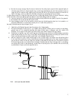

Installation manual_LBT_June 2020
Models:
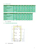
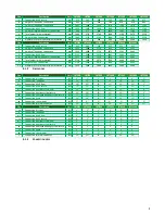
LBT300
LBT3000
LBT500
LBT4000
LBT800
LBT5000
LBT1000 LBT6000
LBT1500 LBT8000
LBT2000 LBT10000
LBT2500
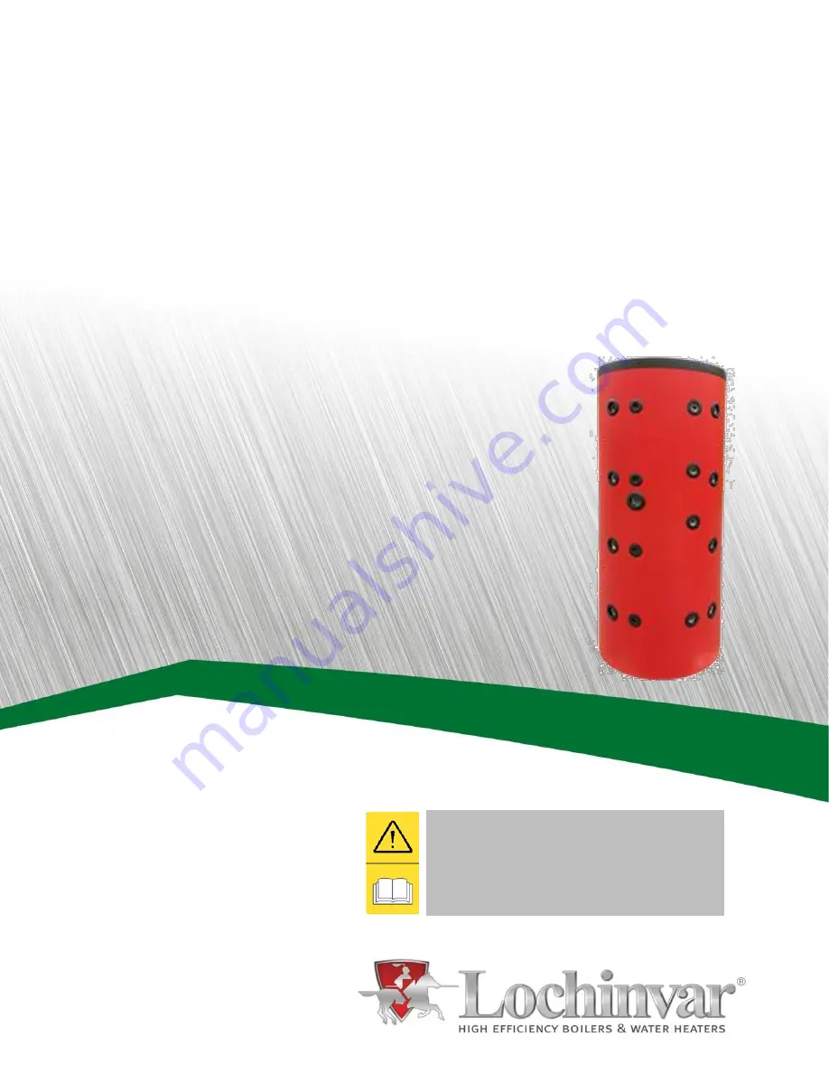
LBT
THERMAL STORE
Installation, Commissioning,
Maintenance and User
Instructions
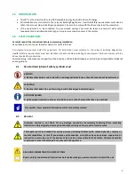
READ AND UNDERSTAND THE INSTRUCTIONS
Read and fully understand all instructions before
attempting to operate maintain or install the unit.


