background image

Model Number:

Serial Number:

Date of Purchase: 

FS 800 Fertilizer Spreader

Owner’s Manual and Parts Book

(Originating w/Serial Number 

76-001 thru 76-145)

12.28.17

N62775 Rev. B

Summary of Contents for FS 800

Page 1: ...Model Number Serial Number Date of Purchase FS 800 Fertilizer Spreader Owner s Manual and Parts Book Originating w Serial Number 76 001 thru 76 145 12 28 17 N62775 Rev B ...

Page 2: ......

Page 3: ...s warranty shall not apply to any machine or attachment which shall have been repaired or altered outside the LOFTNESS factory or authorized LOFTNESS dealership or in any way so as in LOFTNESS judgment to affect its stability or reliability nor which has been subject to misuse negligence or accident nor to any machine or attachment which shall not have been operated in accordance with LOFTNESS pri...

Page 4: ......

Page 5: ...ntenance Safety 5 Hydraulic Safety 5 PTO Safety 5 Chemical Fertilizer Safety 6 Fertilizer Spreader Identification 7 Safety Decal Locations 8 Operation Preparation for Use 9 Connecting to Tractor 9 For PTO Drive Models 9 Attaching PTO 10 Connect Hydraulics and Wiring 10 Connecting to Truck Transporting 10 Setting the Metering Gate Opening 10 Adjusting for High or Low Range 11 Engaging the Conveyor ...

Page 6: ...enance 21 Maintenance Schedule 21 Fluids And Lubricants 21 Lubrication 22 Grease Points 22 Wheel Bearing Maintenance 25 Roller Chains 25 Slip Clutch Adjustment 25 Ground Drive Train Adjustment 26 Hydraulic Surge Brakes Optional 26 Operation 26 Bleeding Brakes 26 Brake Adjustment 26 Removing the Rear End 27 Rear Belt Alignment 27 Optional 540 1000 RPM Dual Drive 27 Adjusting Belt Tension 27 Alignme...

Page 7: ...1000 36 Drive Hydraulic 38 Drive Hydraulic Cont d 40 Drive PTO 42 Drive Ground 44 Drive Ground Cont d 46 Disconnect Hydraulic 48 Electrical 49 Window 50 Manual Holder 50 Machine Decals and Signs 51 Appendix Specifications 53 Dimensions 54 Torque Specifications 55 Inches Hardware and Lock Nuts 55 Metric Hardware and Lock Nuts 56 Table of Contents ...

Page 8: ......

Page 9: ...t to make product improvements to the machine at any time Although great care has been taken to ensure the accuracy of this publication Loftness does not assume any liability for errors or omissions Loftness is not responsible for costs or damages caused by misapplication of fertilizers It is the responsibility of the operator to assure that the fertilizer is applied uniformly and correctly over t...

Page 10: ...plit sprocket design Allows for easy in field replacement of worn sprockets without removal of wheel Integral Lights Sealed and rubber isolated lights tucked neatly and cleanly inside frame Compliant with ASABE standard S279 14 Obstruction Free Interior No internal gussets plates to catch fertilizer Introductions Options Conveyor Drive Mechanical Drive Standard Two speed axle driven transmission H...

Page 11: ...e alert to the possibility of personal injury and carefully read the message that follows If Safety Decals on this machine are ISO two panel pictorial decals are defined as follows The first panel indicates the nature of the hazard The second panel indicates the appropriate avoidance of the hazard Background color is YELLOW Prohibition symbols such as and STOP if used are RED Be certain all machin...

Page 12: ... ear protection respirators gloves hard hats safety shoes and other protective clothing when required The fertilizer spreader should not be used to handle materials other than those which were specified as part of its design It is the operator s responsibility to be aware of the specifications and operate the spreader accordingly It is the operator s responsibility to be aware of machine operation...

Page 13: ...te skin and cause serious injury Never check for leaks by using any part of your body to feel for escaping fluid Always use a piece of wood to check for leaks WARNING Contact with high pressure fluids may cause fluid penetration and burn hazards Fluid that is under pressure can penetrate body tissue Fluid penetration can cause serious injury and possible death If fluid is injected into the skin se...

Page 14: ...haling chemical fertilizers Do not smoke when handling chemical fertilizers Cover food and water containers when spreading around livestock or pet areas Keep bystanders away while spreading fertilizer The spreader should be completely emptied of chemical fertilizer all residue removed and washed with clean water before servicing If symptoms of illness occur during or after handling and or spreadin...

Page 15: ...9L 16 1 12 Ply Tires Jack PTO Drive model shown Only on PTO Drive model Safety Chain Adjustable Height Hitch 540 1000 RPM PTO Spinner Driveline Hydraulic Brake Actuator PTO Storage Cradle Hopper Conveyor Ground Drive Lever Spinners Rear V Belt Covered Rear Gate Lever Conveyor Window ...

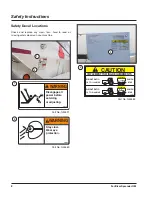
Page 16: ...r machine 1 2 3 Part No N35391 Part No N35383 Part No N35380 WARNING N35391 Disengage all power before servicing or adjusting CAUTION N35383 WITH BRAKES NO BRAKES 20 MPH MAX 25 MPH MAX IMPLEMENT TOWING REQUIREMENTS WEIGHT RATIO 1 TO 1 1 2 MAX 1 1 2 MAX 1 1 4 1 2 MAX WEIGHT RATIO 1 TO 4 1 2 MAX WARNING N35380 Stay clear Wear eye protection 1 3 2 ...

Page 17: ...erneath Perform a test pattern IMPORTANT Before placing the fertilizer spreader into operation a spread pattern test MUST be performed Refer to Spread Pattern Test on page 14 for instructions Connecting to Tractor For PTO Drive Models Adjust the spreader hitch so the spreader is as level as possible Connect to the tractor and install an approved hitch pin for the load securing hitch pin with a saf...

Page 18: ... hitch pin with a safety locking pin Connect the safety chains to the truck Connect surge breakaway chain to the truck Connect the spreader s running light wiring harness to the truck IMPORTANT Make sure PTO is locked in the storage cradle and hydraulic hoses are secure before transport Setting the Metering Gate Opening The application rate is determined by the metering gate opening and the speed ...

Page 19: ...d to use the largest practical gate opening in low range before changing to high range To assure a uniform application rate around field edges make a border application with these adjustments Reduce to 1 2 fan speed gate opening and travel interval CAUTION Do not use a gate setting of 1 5 in 3 81 cm in high range This could cause undue stress on the hopper from a high conveyor speed Operation Enga...

Page 20: ...ance may be beneficial for optimum coverage 1 Make sure all adjustments and a spread pattern has been produced following the Spread Pattern Test and Spread Pattern Adjustments section in this manual 2 From the Spread Pattern Test Results Sheet found on page 16 determine the maximum cc volume value of material in center of pattern 3 Divide this value by two 4 Locate the distance from the zero foot ...

Page 21: ...08 273 672 300 739 58 70 173 99 243 126 309 153 376 180 443 208 512 235 579 263 648 293 720 319 784 60 74 181 103 253 131 323 159 392 189 464 215 528 242 595 273 672 301 741 330 813 62 77 189 107 264 135 333 165 405 194 477 222 547 250 616 281 691 288 709 337 829 65 81 200 113 277 143 352 172 424 204 501 233 573 262 645 293 720 322 792 348 856 67 85 208 116 285 147 363 178 437 210 517 241 592 267 ...

Page 22: ...st must also be performed at the beginning of each season and after adjustments have been made Machine Preparation Ensure the following items are completed before performing the spread pattern test Inspect repair or replace any components that are damaged or not performing properly Make all of the adjustments indicated in this manual Ensure rear end and spinners are clear and free of obstruction D...

Page 23: ...should match your operating speed 4 Engage spinners NOTE During the test note the farthest point from the course and unit center line that material is being spread You will record this on the data sheet see Spread Pattern Test Results Sheet on page 16 For steps 5 7 refer to illustration under Spread Pattern Course for course direction 5 Drive through Flag A with the center of the unit lined up wit...

Page 24: ..._________________________________________________________________________________ ____________________________________________________________________________________________________ Spread Pattern Test Results Recorded Vial Readings 0 L1 L2 L3 L4 L5 L6 L7 L8 R8 R7 R6 R5 R4 R3 R2 R1 0 L1 L2 L3 L4 L5 L6 L7 L8 R8 R7 R6 R5 R4 R3 R2 R1 50 ft Driving Interval 50 ft Driving Interval Spinner Blade Hole L...

Page 25: ...r each vial in its proper square on the Test Pattern Results sheet NOTE Although each vial has marks for measure the most reliable method for measurement is by weight as granular fertilizer components can settle with some irregularity Graphing the Test Results Spread Pattern Test Results Recorded Vial Readings 0 L1 L2 L3 L4 L5 L6 L7 L8 R8 R7 R6 R5 R4 R3 R2 R1 0 L1 L2 L3 L4 L5 L6 L7 L8 R8 R7 R6 R5 ...

Page 26: ... See photo below Increase spinner RPM Pattern 5 High at center Low at sides Move one or two spinner blades to a lowered numbered hole Reduce dimension A See photo below Decrease spinner RPM Pattern 6 Pattern off center Check center divider straighten or center if required Spinner blade settings should be identical on each spinner Check component condition and adjustment settings Refer to Spinner B...

Page 27: ...ck the spinner RPM with tractor engine at full throttle Hold an electronic or mechanical tachometer near one of the spinners to verify the spinner speed Spinner RPM should be approximately 830 WARNING Spinners rotate at high speed Do not get hands or tachometer too close when checking spinner RPM For PTO Model Spreaders NOTE Do not rely on the tractor s RPM gauge to determine the spinner speed Ver...

Page 28: ...20 Fertilizer Spreader OM ...

Page 29: ...Shaft Spinner Conveyor Ground Drive Clip Clutch Metering Gate X Chain Tension X PTO Shaft X X Every 50 V Belt Tension X 540 1000 RPM Belt X Conveyor X Safety Labels X Wheels and Tires X Every 60 Bearing Set Screws X X Every 500 Wheel Bearings X X Jack X Fluids And Lubricants CAUTION Use proper safety procedures when handling petroleum products including but not limited to the use of rubber gloves ...

Page 30: ...me pressure EP rating NOTE Replace any broken or missing grease fittings Be sure to clean fittings before greasing NOTE See Fertilizer Spreader Identification on page 7 for component location and identification 1 2 Location Brake actuator 1 2 Interval Every 8 hours of operation 3 4 5 6 Location Line shaft bearings 3 4 5 6 Interval Every 8 hours of operation Maintenance ...

Page 31: ...9 10 Location Ground drive jack shaft bearings 9 10 Interval Every 8 hours of operation 12 11 Location Slip clutch cylinder bearings 11 12 Interval Every 8 hours of operation 13 14 15 16 17 Location Spinner bearings top PTO drive models only 13 14 Spinner bearings bottom 15 16 Idler pulley bearing 17 Interval Every 8 hours of operation Maintenance ...

Page 32: ...Interval Every 8 hours of operation 21 20 23 22 Location Conveyor roller bearings front 20 21 Conveyor roller bearings rear 22 23 Interval Every 8 hours of operation 24 Location PTO shaft 24 Interval Every 8 hours of operation 25 Location PTO tube and U joints 25 Interval Every 8 hours of operation Maintenance ...

Page 33: ...spindles Repack bearings by forcing grease between the rollers Assemble washer and nut on spindle and rotate hub while tightening the nut to 20 25 ft lbs Back off the nut until it becomes loose While rotating the hub hand tighten the nut and alight the cotter pin hole in the spindle with the slot in the nut There should be 001 005 in of end play Insert cotter pin and bend it around the nut Roller ...

Page 34: ... fitting on the drum and place end of hose in a clean container 5 Operate safety breakaway lever to fill and bleed the system Add fluid as required DO NOT pump reservoir empty as air will be introduced into the system 6 Purge each cylinder one at a time until system is completely free of air Close bleeder screw as each cylinder is purged 7 Breakaway lever will pull up to a hard stop when all air h...

Page 35: ... D and E to run same surface of belt through the grooves of the line shaft and idler pulleys Section of belt marked as F should be tightened so 1 in 2 54 cm deflection occurs with 20 lbs of pressure applied at mid point between the line shaft sheave and the idler sheave Tension should be rechecked after 2 hours of field use To tighten belt tension loosen inner nut on the belt tension bolt 6 and ti...

Page 36: ... sprayer clean the conveyor rear end spinners and everywhere that the fertilizer accumulates IMPORTANT To avoid damage to the conveyor mechanism make sure all fertilizer is removed in the areas around the spinners and on the floor of the spreader Storage Because of the corrosiveness of granular fertilizers the machine should be kept clean and lubricated to extend the life of the machine and preven...

Page 37: ...ering gate setting and ensure operation range is correct Fertilizer build up on floor and around metering gate Clear fertilizer build up Spread pattern not the same on both sides of the spreader For PTO drive models check wrap on rear V belt Tighten adjust rear V belt Rear deflector and or divider is misaligned Check alignment Spinners height not consistent Verify and adjust spinners to be the sam...

Page 38: ...30 Fertilizer Spreader OM ...

Page 39: ...31 Fertilizer Spreader OM PARTS IDENTIFICATION AND HYDRAULIC SCHEMATICS Parts Identification ...

Page 40: ... WLDMT 2 1 N23873 KNOB 3 8 X 1 1 2 FOUR PRONG 3 1 N43362 POINTER SPREADER GAUGE 4 1 N43352 ADJUSTER GATE 5 1 N50260 CHAIN SAFETY 21 000LB W HDWR 6 1 8047 JACK BULLDOG SWL 158DTSF 7 1 N43400 GATE WLDMT 8 1 N43498 SPROCKET 50B22 1 4 KEYWAY SS 5 6 1 2 3 4 7 8 Parts Identification ...

Page 41: ...RRIAGE 1 2 X 6 GR 5 4 1 N43841 SPROCKET WLDMT IDLER 5 4 N62391 BOLT CARRIAGE 5 16 X 1 1 4 SS 6 1 N41429 BELT FLATWIRE 7 X241 7 2 N62318 PLATE SPREADER B 8 1 N51441 DRUM WLDMT DRIVER 9 6 N33830 BEARING 1 DODGE 3 BOLT FLG 10 14 N41428 BOLT CARRIAGE 5 16 X 1 SS 11 18 N41427 NUT LOCK 5 16 SER FLG SS 4 3 2 1 5 6 7 8 9 10 11 Parts Identification ...

Page 42: ...ion Parts Identification 1 2 3 4 5 5 6 17 19 7 16 21 8 9 10 11 10 10 12 13 14 2 15 1 22 24 23 20 18 NOTE Complete four brake system N41372 is shown N41373 two brake option has brakes installed on the front axle only N41374 option has no brakes installed ...

Page 43: ...2 N35349 RING SPRDR WHL DRIVE RETAIN 13 8 4538 BOLT 3 8 X 2 3 4 GRADE 5 14 2 N41444 BRAKE FREE BACKING 13 LEFT 15 2 N47644 HUB DRIVE 16 8 4033 BOLT CARRIAGE 3 8 X 3 4 GR5 17 4 4577 BOLT 3 4 X 5 FN TH GR 8 18 16 4341 NUT 3 4 FINE THREAD GRADE 8 19 4 N41451 PLATE SPREADER SPRING MOUNT 20 2 N16700 NUT 1 14GR 8FINE THREADTOPLOCK 21 4 N16352 NUT LOCK 3 4 GRADE 8 FINE 22 2 N28583 BOLT 1 X 6 FN TH GR 8 2...

Page 44: ...ilizer Spreader OM Driveline 540 1000 1 6 6 10 13 16 13 14 12 15 21 8 13 32 31 27 30 9 10 35 33 34 29 29 28 8 9 10 9 8 9 10 17 18 19 20 36 24 8 9 10 33 25 26 12 8 4 23 22 9 8 3 4 7 11 2 5 Parts Identification ...

Page 45: ...TTN BRL 16 1 N39162 PULLEY 2BK27 X 1 TTN BRL 17 1 N43548 MOUNT WLDMT SHAFT 1000RPM 18 3 N31741 WASHER FLAT 3 8 SAE 19 3 4005 BOLT 3 8 X 1 1 4 GRADE 5 20 1 N41458 SHAFT SPREADER PTO DRIVE 21 1 N41664 SHAFT PTO 540 1000 22 1 N33992 SHAFT 1 3 8 21 SPLINED 6 23 1 4232 BOLT 3 8 X 1 3 4 GRADE 5 24 1 N62284 SHIELD SPREADER DRIVESHAFT 25 2 N36497 BOLT 3 8 X 3 4 SER FLG 26 1 N62281 SUPPORT DRIVESHAFT 27 1 ...

Page 46: ...38 Fertilizer Spreader OM Drive Hydraulic 1 3 6 2 5 8 5 4 5 15 19 17 18 16 12 16 15 13 13 14 17 18 4 5 11 10 21 5 7 5 4 8 9 4 20 Parts Identification ...

Page 47: ...DUAL SPNR STOP 8 4 4567 BOLT CARRIAGE 3 8 X 1 SS 9 6 N41427 NUT LOCK 5 16 SER FLG SS 10 6 N41428 BOLT CARRIAGE 5 16 X 1 SS 11 2 N33830 BEARING 1 DODGE 3 BOLT FLG 12 1 N51082 DEFLECTOR SPREADER SPINNER 13 2 N62261 SHIELD SPREADER SPINNER SHAFT 14 4 N44111 SLINGER LH 15 16 4000 BOLT 1 4 X 1 GRADE 5 16 2 N62257 SPINNER 17 16 4231 WASHER LOCK 1 4 18 16 4230 NUT STANDARD 1 4 19 4 N33836 SLINGER RH 20 1...

Page 48: ...40 Fertilizer Spreader OM Drive Hydraulic Cont d 2 1 3 4 5 3 5 6 7 8 10 9 11 12 13 14 15 16 2 4 17 21 20 19 16 11 18 18 Item 21 hose holder bracket located on tongue of spreader Parts Identification ...

Page 49: ...83 WASHER FLAT 1 4 9 2 4001 BOLT 1 4 X 1 3 4 GRADE 5 10 1 N53062_01 HOSE 3 8 X 14 6FJX 6FJX 11 1 N62067 HOSE 3 8 X 280 6FJIC 8MP 12 1 N16169 TEE 6MJIC 6MOR 6MJIC 13 1 N55947 VALVE CHECK 06MOR 06MJIC 14 1 N34022 ADAPTER 6MOR 8MOR 15 1 N55949 VALVE CHECK 08MOR 08MJIC 16 1 N61596 HOSE 3 8 X 269 375 8FJIC 8MP 17 1 N55850 TEE 06FOR 06F0R 06MOR 18 2 N11825 COUPLER 1 2 MALE PIONEER 19 16 4979 NUT LOCK 3 ...

Page 50: ...42 Fertilizer Spreader OM Drive PTO 12 13 15 14 1 14 20 9 21 22 3 4 3 4 2 2 5 7 9 10 11 6 7 8 15 13 18 19 3 4 3 4 16 12 Parts Identification ...

Page 51: ...143 PIN SPREADER BELT SHIELD 9 15 N73940 NUT LOCK 3 8 SER FLG SS 10 4 4567 BOLT CARRIAGE 3 8 X 1 SS 11 1 N43972 GUARD SPREADER SPINNER 12 16 N68478 BOLT 1 4 X 1 SS 13 4 N33836 SLINGER RH 14 16 N68480 NUT LOCK 1 4 SER FLG SS 15 2 N43950 SPINNER 16 4 N44111 SLINGER LH 17 1 N51082 DEFLECTOR SPREADER SPINNER 18 2 7187 03 KEY 1 4 X 1 1 2 19 15 N50815 BOLT 3 8 X 1 SS SER FL GR 5 20 1 N44105 DIVIDER SPRD...

Page 52: ... Detail A 22 21 1 19 20 16 18 15 14 13 12 9 7 6 6 2 3 8 3 5 2x 11 2x 5 2x 10 2x 5 2x 4 2x 17 23 24 25 26 23 27 28 29 30 32 31 33 34 35 36 internal 37 internal 37 See parts list for replacement connecting links for item number 7 See page 46 for parts breakdown of this detail ...

Page 53: ... N47644 HUB DRIVE 16 3 N47855 BOLT 3 8 X 1 1 4 SER FLG 17 1 N43322 BUSHING SPRDR WHL DRIVE 18 1 4313 BOLT 3 8 X 2 1 2 GRADE 5 19 1 N62727 COVER SPRDR WHL DRIVE CHAIN 20 1 N33893 CLUTCH RATCHED SLIP SC X4 21 1 7187 03 KEY 1 4 X 1 1 2 22 1 4250 NUT STANDARD 1 2 23 2 4068 WASHER 1 2 SAE FLAT 24 1 N33907 SPRING 6 CLUTCH 25 2 N33830 BEARING 1 DODGE 3 BOLT FLG 26 3 N41428 BOLT CARRIAGE 5 16 X 1 SS 27 1 ...

Page 54: ...46 Fertilizer Spreader OM Drive Ground Cont d 15 16 17 3 18 19 20 16 21 1 2 3 4 5 12 13 14 9 10 11 8 7 6 See parts list for replacement connecting links for item number 7 Parts Identification ...

Page 55: ...AIN HALF SS 8 1 N47307 SPROCKET COMBINATION 50X40 20 9 1 N33889 TENSIONER MOS2 3 5 DIA 10 1 4569 BOLT CARRIAGE 3 8 X 5 SS FT 11 1 N43801 WASHER SPREADER 1 75 X 40 12 2 N33830 BEARING 1 DODGE 3 BOLT FLG 13 6 N41427 NUT LOCK 5 16 SER FLG SS 14 6 N41428 BOLT CARRIAGE 5 16 X 1 SS 15 1 N45532 BASE SPRDR CLUTCH SPRKT 16 4 N37062 BUSHING 1 ID NYLON X 1 LG 17 2 4105 GREASE ZERK 1 4 SCREW IN 18 1 N33958 BO...

Page 56: ...ESCRIPTION 1 2 4979 NUT LOCK 3 8 SER FLG 2 3 N43520 PLATE SPREADER CYL CLAMP 3 2 N43518 BODY CLAMP 1 75 4 1 N43516 CYLINDER 1 1 2 x3 5 2 4456 BOLT 3 8 X 4 GRADE 5 6 2 N28824 ADAPTER 6MJIC 4MOR 7 2 N66861 HOSE 1 4 X 257 8MPT 6FJX 8 2 N11825 COUPLER 1 2 MALE PIONEER Parts Identification ...

Page 57: ...AT 2 1 N44871 HARNESS SPREADER FRONT 3 1 N62707 HARNESS SPREADER REAR 4 2 N41423 LIGHT 4 STTL AMBER 5 4 N41426 GROMMET 4 STTL 6 2 N41422 LIGHT 4 STTL RED 7 1 N62625 MODULE LIGHTING 8 2 N22358 BOLT 10 32 X 3 4 BHCS 9 2 N16334 NUT NYLON INSERT 10 1 2 3 4 5 4 5 7 8 9 6 5 6 5 Parts Identification ...

Page 58: ...AL FS800 2 3 4573 BOLT 1 4 X 3 4 SER FLANGE 3 3 4996 NUT LOCK 1 4 NYLOCK 4 1 N19600 HOLDER 01 315A STND MANUAL QTY PART DESCRIPTION 1 6 4573 BOLT 1 4 X 3 4 SER FLANGE 2 6 4460 WASHER 1 4 SAE FLAT 3 6 4996 NUT LOCK 1 4 NYLOCK 4 1 N37022 WINDOW SPREADER FRONT 1 2 3 4 1 2 3 4 Parts Identification ...

Page 59: ...EIGHT RATIO 1 TO 1 1 2 MAX 1 1 2 MAX 1 1 4 1 2 MAX WEIGHT RATIO 1 TO 4 1 2 MAX WARNING N35380 Stay clear Wear eye protection N35384 TORQUE WHEEL BOLTS TO 100 FT LBS CHECK DAILY N35387 IMPORTANT 1 KNOW THE WEIGHT OF THE MATERIAL TO BE SPREAD Weigh one gallon and multiply by 7 5 2 CONSULT APPLICATION RATE CHART FOR GATE OPENING SETTING 3 LOCK GATE AFTER SETTING 4 CHECK SPREAD PATTERN 5 KEEP CONVEYOR...

Page 60: ...88 194 203 217 232 305 340 382 409 428 441 463 478 500 534 571 144 160 180 192 198 205 215 222 232 248 265 354 394 443 473 487 505 529 546 571 610 652 163 182 204 217 223 231 242 246 257 277 298 401 448 502 534 549 569 596 606 633 682 734 183 203 228 243 252 259 270 277 296 305 323 450 500 561 598 620 638 665 682 729 751 795 203 225 252 270 278 266 297 304 314 331 351 500 554 620 665 684 655 731 7...

Page 61: ...kg Tires 19L 16 1 12 ply Axles Suspension Walking tandem 10 000 lb axles 2 5 in wide leaf springs Frame 6 x 3 x 1 8 in rectangular tubing Hitch in hot rolled sheet channel formed Drawbar Bolt in adjustable position Hopper 12 gauge 409 stainless steel Skid 12 gauge 409 stainless steel Gate 7 gauge 409 stainless steel Conveyor Chain 7 in wide 304 stainless steel with 1 in x 1 in mesh Spinner Dish 19...

Page 62: ... Fertilizer Spreader OM Appendix DESCRIPTION FS 800 FERTILIZER SPREADER Length A 215 5 in 547 4 cm Hopper Width B 92 in 233 7 cm Height C 91 6 in 232 6 cm Wheel Width D 92 9 in 235 9 cm Dimensions B D C A ...

Page 63: ...55 Fertilizer Spreader OM Appendix Torque Specifications Inches Hardware and Lock Nuts ...

Page 64: ...56 Fertilizer Spreader OM Appendix Torque Specifications Cont d Metric Hardware and Lock Nuts ...

Page 65: ......

Page 66: ...www loftness com Loftness Specialized Equipment Inc 650 So Main Street PO Box 337 Hector MN 55342 Tel 320 848 6266 Fax 320 848 6269 Toll Free 1 800 828 7624 Printed in USA Loftness 2017 ...

Reviews: