TEMPERATURE RECORDER
C
ONFIGURING THE
ECORDER
R
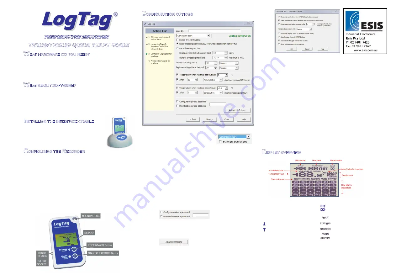
The Recorder must be configured before you can take readings.
Start the LogTag Analyzer software.
Insert the Recorder into the Interface Cradle with the blue label to the
front. You will here a click as the contacts engage.
The screen will show ‘
’.
If a Recorder has been used previously, a chart will appear.
Select ‘
’ - ‘
’ to bring up the configuration wizard. The
‘
’ will be displayed.
Click on ‘
’; LogTag Analyzer will scan for a Recorder, once found the
configuration options will be displayed.
?
?
?
?
?
?
A new LogTag has been detected..... Please
wait.....
LogTag
Wizard
Welcome and general instructions
Next
TRID30/TRED30 QUICK START GUIDE
W
W
I
HAT HARDWARE DO YOU NEED?
HAT ABOUT SOFTWARE?
NSTALLING THE INTERFACE CRADLE
?
?
?
?
LogTag TRID30-7 or TRED30-7 Temperature recorder.
TRED30-7 requires an external Sensor (ST100x-xx).
LogTag LTI/USB Interface Cradle.
PC running Windows XP or later version.
LogTag Analyzer software is available for download from LogTag Recorders
website.
Goto http://www.logtagrecorders.com/software/ after registering; you will
be e-mailed a link, from where you can download the software.
After installation is complete, a new icon will appear on your desktop.
Plug the Interface Cradle into a USB port.
USB drivers will install automatically. Your
operating system will inform you when
installation is complete.
?
?
?
?
?
?
?
?
?
?
?
?
?
?
?
User ID - user can enter details about each Recorder.
Select ‘
’ or ‘
’
depending on requirements.
Enter the start Date and Time if selected.
Tick ‘
. Enabling this function causes the Recorder
to start taking readings immediately after configuration (useful in case the
user forgets to press the Start button).
Select recording mode - Continuously (overwrites old readings when
memory is full) or Reading for a specific time (note that changing the
recording interval automatically re-calculates the recording duration).
Enter a start delay if required (allows the Recorder to stabilise before
recording starts).
Set a upper temperature alert value and tick
if you require a
visual upper
to show on the Recorder’s display once triggered.
Set a lower temperature alert value and tick
if you require a
visual lower
to show on the Recorder’s display once triggered.
You can also setup various trigger conditions for both the upper and lower
alarms, single violation or a set of consecutive violation readings or a
total of violation readings encountered (called accumulative).
If you wish to control future configuration of this Recorder, tick the
box and enter a password. You can also
control future downloads, tick the
.
NOTE: Passwords are case sensitive.
Click ‘Advanced options’ to view and change the Recorder’s Advanced
features including the
function, Stopping and Re-activation,
Clearing and Latching Alarms, Power save and displayed units ºC or ºF.
Push button start
Date/Time start
Enable pre-start logging’
‘Trigger alarm’
‘
’
‘Trigger alarm’
‘
’
‘Configure requires a password’
‘Download requires a password’
‘Pause’
ALARM
ALARM
C
ONFIGURATION OPTIONS
?
?
?
?
?
?
?
?
If enabled, any button activity will prevent readings being processed for
max/min/duration statistics and alarm triggers for the configured paused
duration. This allows the user to review current statistics or clear an
alarm without causing a false alarm or statistic while handling the
Recorder.
The Recorder can display temperature in units of ºC or ºF, select the
units you require.
The option ‘Switch off the display after 30 seconds (Power save)’ will
extend battery by automatically deactivating the display after 30
seconds of no button activity, button activity will temporarily reactivate
the display.
The Recorder can be configured to allow the user to Stop and/or Re-
activate the Recorder, tick which options are required.
Click ‘OK’ to exit the Advanced dialog, returning to Configuration
Options.
Click and the Recorder will be configured.
When configuration is complete remove the Recorder from the Interface
Cradle.
If you wish to configure more Recorders with the same configuration
profile, insert the next Recorder into the Interface Cradle and click
. Repeat until all Recorders are configured.
‘Next’
‘Again’
D
ISPLAY OVERVIEW
The temperature can be displayed in
or
.
Reading type:-
= The temperature of the last reading taken.
= The maximum reading in a given 24hour period.
= The minimum reading in a given 24hour period.
Above/below limit markers:-
Up arrow marker appears when the temperature
displayed is above the upper alert limit.
Down arrow marker appears when the temperature
displayed is below the lower alert level.
appears when an alarm is triggered.
The time (in HH:MM) can be current time, time remaining
to start of a delayed start or duration of a given max min
value above or below the specified limits. The value
displayed is indicated by the following:-
= displaying Current Time.
= displaying DELAYED START time
remaining.
= displaying duration of a given MAX or
MIN statistic above/below the limits on
a given day.
ºC
ºF
Battery test is performed hourly:-
displayed when battery tested OK
displayed when battery tested LOW.
State indicators:-
Ready to start recording.
Preparing to start recording. If a delayed
start is configured then displays time
remaining to start recording.
Recording.
Max/Min statistics collection paused due
to button press activity.
Recording has stopped.
The display is organized with a table of ‘day alarm
indicators’ segments named “Today” to “-29d” which are
switched on when a given day has an alarm trigger
present.
The day number of the currently selected day statistic is
displayed when in review mode. TODAY is day 0,
yesterday is day ‘-1'. Can be configured to display the
total number of days collected while recording.
READY
STARTING
PAUSED
STOPPED
DURATION
TIME
TIME DELAY
ALARM
MIN
MAX
CURRENT
RECORDING
®
®
Document Revision C 070911 - © Copyright 2011, LogTag Records Ltd. LogTag is a registered trade mark of LogTag Recorders Ltd.
®


