background image


LEON MRI  

Proven, intuitive, stable. 


Specially developed for use in a cardiac cathlabs or MRI ƒ  


For all patient groups 


Azeer Anesthesia 

Workstation

Azeer Intinsive Care 
Ventilators Elisa Family

Summary of Contents for elisa 300

Page 1: ...LEON MRI Proven intuitive stable Specially developed for use in a cardiac cathlabs or MRI ƒ For all patient groups Azeer Anesthesia Workstation Azeer Intinsive Care Ventilators Elisa Family ...

Page 2: ...elisa 300 elisa 500 Instructions for Use Compendium Basic Manual Supplement A Supplement B Supplement C Supplement D Supplement E Supplement F ...

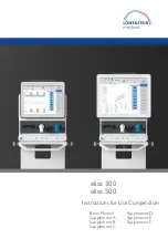
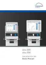
Page 3: ...elisa 300 elisa 500 Instructions for Use Basic Manual ...

Page 4: ...facturer The user of the device shall have sole responsibility for any malfunction or damage which is due to improper use poor maintenance improper service improper repairs or modifications carried out by unauthorised persons Each device has either a serial number or a UDI Unique Device Identification Serial number system The coding system contains the code for the product group 03 or 05 the year ...

Page 5: ... 3 General safety instructions 17 3 1 General safety instructions 18 3 1 1 Safety standards 22 3 1 2 Safety functions 23 3 1 3 Work carried out on the device 25 4 Components and assembly 27 4 1 System overview 28 4 2 Main components and views 29 4 2 1 Front view 29 4 2 2 Back 30 4 2 3 Side view 31 4 2 4Valve bar 32 4 2 4 1Valve bar modules 32 4 2 4 2 Removing the valve bar 34 4 2 4 3 Installing th...

Page 6: ...5 1 3 Adjust the ventilation screen 48 5 2 Configuration 50 5 3 Symbols 50 5 4 Abbreviations and terms used in the instructions for use and in the user guid ance 52 6 Preparing the system for use 61 6 1 Power supply 62 6 1 1 Mains supply 62 6 1 2 Internal power supply rechargeable battery 62 6 2 Gas supply 64 6 3 Switching power on and off 65 6 3 1 Automatic patient detection APD 65 6 4 Power up t...

Page 7: ...rm limits 91 7 3 7 1Ventilation alarms 91 7 3 7 2 Gas 91 7 3 7 3 Other alarms 92 7 3 7 4 Alarm limits for non invasive ventilation 92 7 3 8 Drug nebulization 93 7 3 9 Start ventilation Stop ventilation 93 7 3 10 Configuration options on the ventilation screen end user 94 7 3 10 1 Curve display unit of measurement as configured 94 7 3 10 2 Trend graphs compressed trend graphs 95 7 3 10 3 Data table...

Page 8: ... system test 164 10 Cleaning disinfection and sterilisation disposal 169 10 1 General information 170 10 1 1 Initial operation 170 10 2 Cleaning and disinfection 171 10 2 1 Intensive care ventilator 171 10 2 2Valve bar 172 10 3 Disposal of elisa 300 elisa 500 177 11 Maintenance 179 11 1 General 180 11 2 Oxygen measurement O2 180 11 2 1 Calibration of the paramagnetic O2 sensor 181 11 3 Air filter ...

Page 9: ...th terminal devices 200 12 10 Guidance and manufacturer s declaration 202 13 Default parameters 207 13 1 Default parameters factory settings 208 13 1 1 Default parameters 208 13 1 2 Adjustment ranges 209 13 1 3 Default alarm limits 209 13 1 3 1 Default alarm limits of the ALPV mode 211 13 1 3 2 Default alarm limits of the WOBOV mode 211 13 1 3 3 Default alarm limits of the CPR mode 212 ...

Page 10: ...8 Basic Instructions for Use elisa 300 500 SW 2 09 x Rev 11 0 Contents This page is intentionally left blank ...

Page 11: ...About this manual 1 Basic Instructions for Use elisa 300 500 SW 2 09 x Rev 11 9 1 1 About this manual 10 1 2 Safety information in these instructions for use 10 1 About this manual ...

Page 12: ...elisa 500 Manoeuvres Functions Venti lation Modes IFU Supplement B elisa 300 to elisa 800VIT LeoCap IFU Supplement C elisa 300 to elisa 800VIT LeoLyzer IFU Supplement D elisa 300 to elisa 800VIT Pulse oximetry and LeoClac IFU Supplement E elisa 300 to elisa 800VIT External interfaces IFU Supplement F elisa 300 to elisa 800VIT elisa megs The manufacturer reserves the right to further develop the de...

Page 13: ...ic Instructions for Use elisa 300 500 SW 2 09 x Rev 11 11 Warning Warning refers to a situation which may cause injuries to the user or the patient Caution Caution refers to a situation which may cause damage to the equipment ...

Page 14: ...1 About this manual 12 Basic Instructions for Use elisa 300 500 SW 2 09 x Rev 11 This page is intentionally left blank ...

Page 15: ...Use 2 Basic Instructions for Use elisa 300 500 SW 2 09 x Rev 11 13 2 1 Intended use 14 2 2 Areas of application 14 2 3 Differences between elisa 300 and elisa 500 15 2 Use ...

Page 16: ...s elisa 300 elisa 500 can also be used as an anaesthesia workstation For more details please refer to the separate document Instructions for Use Supplement A Manoeuvres Functions Ventilation Modes For a description of the device functions please refer to chapter 5 1 General description of the equipment functions 2 2 Areas of application elisa 300 elisa 500 is approved for stationary use and patien...

Page 17: ...een elisa 300 and elisa 500 Hardware options elisa 300 elisa 500 Screen diagonal 12 1 15 BF interfaces 2 x BF interface 4 x BF interface Software options elisa 300 elisa 500 Cuffscout function not available standard Peso function not available standard IAP function not available standard ...

Page 18: ...2 Use 16 Basic Instructions for Use elisa 300 500 SW 2 09 x Rev 11 This page is intentionally left blank ...

Page 19: ...ions 3 Basic Instructions for Use elisa 300 500 SW 2 09 x Rev 11 17 3 1 General safety instructions 18 3 1 1 Safety standards 22 3 1 2 Safety functions 23 3 1 3 Work carried out on the device 25 3 General safety instructions ...

Page 20: ...se of the equipment to ensure safe operation Please contact your sales organization to receive the required training Secure positioning Verify the secure positioning of the device which must not be tilted or set up at an angle Moving the cart with the device Check that the device is securely fastened on the cart Release the locking brakes on the cart wheels When moving the cart over thresholds or ...

Page 21: ... are approved for use with the device If employing different accessories the user is required to test and demonstrate the safety of the system prior to its use Restrictions regarding the application of the breathing circuits used must be observed drug nebulization In order to prevent adverse effects on the ventilator performance prolonged mean expiration time AutoPEEP false triggering flow generat...

Page 22: ...s sensor LeoLyzer SpO2 sensor Nurse call elisa megs medical device interface Warning Only accessories included in the accessory list may be connected to the type BF connection ports Warning Always connect type BF equipment to the device before connect ing it to the patient Warning Be sure to connect the equipment to the appropriate interfaces on the back of the device Check that all connectors are...

Page 23: ...e accessories from the patient during defibrillation The housing must be dry before the device is connected to the mains supply It must be ensured that the supply voltage corresponds to the ratings on the type plate on the back panel of the device The system must be stored and operated at the temperature and humidity levels indicated in chapter 12 4 Technical specifications The system must always ...

Page 24: ...nity can cause interference The correct performance of elisa 300 elisa 500 must be verified prior to connecting the patient to the device Remark All the elisa 300 elisa 500 features are fully functional if the place of use meets the EMC requirements set forth in the applicable regulations Detailed information on electromagnetic compatibil ity can be found in chapter 12 10 Guidance and manufacturer...

Page 25: ...c safety and essential performance of respiratory gas monitors EN 62304 Medical device software Software life cycle processes EN 62366 Medical devices Application of usability engineering to medical devices ISO 14971 Medical devices Application of risk management to medical devices DIN EN ISO 80601 2 13 Particular requirements for basic safety and essential performance of an anaes thetic workstati...

Page 26: ... with the appropriate sensors gas concentration of CO2 sevoflurane isoflurane Patient alarms are only evaluated during ventilation and when the automatic patient detection function detects a patient An alarm is triggered when applicable System test As a matter of principle a system test must be carried out before the ventilator is used Warning Never carry out a system test if a patient is connecte...

Page 27: ...ied accuracy and tolerance ranges Remark After changing the patient category it is not possible to skip the system test 3 1 3 Work carried out on the device Repairs service and maintenance on the device must only be carried out by au thorised personnel The maintenance intervals and measures are described in chapter 11 Maintenance Warning Never carry out repair service or maintenance work if a pati...

Page 28: ...3 General safety instructions 26 Basic Instructions for Use elisa 300 500 SW 2 09 x Rev 11 This page is intentionally left blank ...

Page 29: ...view 31 4 2 4Valve bar 32 4 2 4 1Valve bar modules 32 4 2 4 2 Removing the valve bar 34 4 2 4 3 Installing the valve bar 34 4 2 5 Battery 34 4 3 Cart option 35 4 4 Breathing circuit 36 4 5 Tube hanger 37 4 6 Respiratory gas humidification 37 4 6 1 Connection with an active respiratory gas humidifier 38 4 6 2 Connection with a passive HME filter 39 4 Components and assembly ...

Page 30: ...elisa 500 are A Intensive care ventilator with integrated control unit including the valve bar and the rechargeable battery A B elisa 300 A B elisa 500 Furthermore the ventilation system can be expanded to include the following options B Cart with 2 standard rails on the sides and a standard rail in the middle whose height is adjustable Tube hanger not shown ...

Page 31: ...D F B J G E elisa 500 A Power ON button B Expiratory flow sensor C Paux I D Expiratory port E Paux II F Inspiratory port G Pneumatic nebulizer connection H Exhaust gas port on the side of the device J Alarm LED Caution The ventilator and the connected accessories must not be cov ered during operation or while the internal power supply system is charging ...

Page 32: ...see Detailed view of the inter faces D Button to release turbine filter cover E Type plate F Fan G Battery compartment I and II H Power input J Oxygen supply Detailed view of the interfaces Picture Designation Assignment 1 A 3 2 B 4 A and B PDMS Monitor interface configurable 1 and 2 Serial interface type BF configurable 3 and 4 Serial interface type BF configurable elisa 500 only ...

Page 33: ...on Only devices which comply with the EN 60601 1 and or EN 60950 standard may be connected to the interfaces of elisa 300 elisa 500 Remark Do not touch interfaces A or B or C and the patient at the same time 4 2 3 Side view The elisa 300 elisa 500 control unit can be tilted manually by approx 30 A elisa 300 B A elisa 500 B A Cover of the turbine air filter B Tilting the control unit ...

Page 34: ...following elements A Inspiratory valve B Expiratory valve C Expiratory flow sensor C A B elisa 300 C A B elisa 500 4 2 4 1 Valve bar modules Warning The modules used need to be reprocessed before each use see chapter 10 Warning Before each use of the valve bar modules visually check each module for damage Make sure that components are intact and complete Do not use a module that is damaged or inco...

Page 35: ...ne E Valve basket with mushroom valve F Expiratory valve G F H G PEEP membrane 3 parts consist ing of silicone membrane disc and silicone disc Do not disassemble the PEEP membrane This is neither allowed nor necessary H Sealing ring expiratory valve Check the proper fit of the sealing ring L Expiratory flow sensor L M N M Sealing plate N Sealing ring expiratory flow sensor Check the proper fit of ...

Page 36: ...embled in reverse order Introduce the modules into their respective slots at a slight angle from below and push them upwards Make sure that the mechanical locks engage Warning All valve bar modules must be reprocessed before a patient may be connected to the ventilator Remark Observe the correct sequence when inserting the inspiratory and expiratory valve 4 2 5 Battery elisa 300 elisa 500 can be e...

Page 37: ...n any of the two battery compartments Close the battery compartment with the cover Further information on battery usage can be found in chapter 6 1 2 Internal supply system rechargeable bat tery 4 3 Cart option Place the ventilator on the cart Be sure to hold it only at the carrying handle at the top of the device Fasten the ventilator using the locking mechanism on the bottom of the platform Acce...

Page 38: ...00 the cart accepts a maximum load of 10 kg which is limited to 5 kg per standard rail 4 4 Breathing circuit Operate elisa 300 elisa 500 only in conjunction with breathing circuits and ac cessories that meet the requirements specified in chapter 3 1 General safety instructions Compliance resistance and leakage of the tubing system used are measured individually in the system test Patient category ...

Page 39: ...andles on the cart 4 6 Respiratory gas humidification For warming and humidifying the respiratory gases elisa 300 elisa 500 can be combined with various accessories for respiratory gas conditioning Use only equipment that meets the requirements specified in chapter 3 1 General safety instructions Warning To avoid additional flow resistances filter systems e g HME should not be used at the same tim...

Page 40: ...ormation on connecting the breathing circuit to the active respiratory gas humidifier refer to the information pro vided by the manufacturer Warning Active humidifiers increase the resistance of the ventilation sys tem Warning To guarantee proper channelling of water condensation the hu midifier must be positioned well below the inspiratory or expir atory port Warning Do not fasten the respiratory...

Page 41: ...passive HME filter between theY connector and the patient Remark Filters increase the dead space volume and the resistance of the ventilation system Warning Residual drug build up from nebulization may cause high flow re sistance which may eventually block ventilation Warning Regularly check the filter for increased resistance or clogging ...

Page 42: ...5 General information 40 Basic Instructions for Use elisa 300 500 SW 2 09 x Rev 11 This page is intentionally left blank ...

Page 43: ... 44 5 1 2 1 Open close windows 44 5 1 2 2 Confirmation Enter 44 5 1 2 3 Edit parameters 44 5 1 2 4 Selector 44 5 1 2 5Views 46 5 1 2 6 Stop graphs 46 5 1 2 7 Home 46 5 1 2 8 Symbols Functions 47 5 1 2 9 Help function 47 5 1 3 Adjust the ventilation screen 48 5 2 Configuration 50 5 3 Symbols 50 5 4 Abbreviations and terms used in the instructions for use and in the user guidance 52 5 General inform...

Page 44: ...d in the inspiratory valve Power supply is assured by connection to mains power and the integrated bat tery The battery powers the ventilator in case of mains failure and mains power fluctuations as well as during patient transport within the health care facility Oxygen O2 is supplied via a wall outlet or from a gas cylinder AIR is supplied by the integrated turbine Software functions are provided...

Page 45: ...anged A D C B E F G H P K L M N A Status line B Selected ventilation mode C Dynamic view of the lung D Toolbox with shortcuts 7 of them are user configurable E Alarm pause button F Home button back to main screen G Backup mode button H Button bar if a value has been selected selector K Enter button confirms selected actions or parameters L Home Status and Trends tabs M Number of configured views m...

Page 46: ...or is shown on the right hand side of the screen Turn the selector by swiping to the new value and confirm the selection with the Enter button To cancel the input and return to the main screen press the button of the se lected parameter once again or touch the screen anywhere outside the selector 5 1 2 4 Selector You open the selector by selecting an editable parameter The selector displays the fo...

Page 47: ...ic Instructions for Use elisa 300 500 SW 2 09 x Rev 11 45 Figure 1 Figure 2 Figure 3 A C D E B B F Remark To prevent the adjustment of potentially hazardous settings a warning is displayed which must be acknowledged separately ...

Page 48: ... 6 Stop graphs A STOP button is provided in the upper right hand corner of the graph window When you touch this button the following will happen All the active graphs will freeze A Restart Graphs button will appear to unfreeze the graphs Movable cursors will appear which can be used to perform measurements on the graphs By moving a cursor you can view the corresponding measured values Pressure mba...

Page 49: ...t screen you will find a Help button which can be pressed to view pictures illustrating the correct assembly and positioning of the valve bar components Tap a valve to obtain interactive instructions for the valve concerned In the standby mode and during ventilation you can use the Help function to obtain information about the different ventilation modes parameter settings and alarm limits To view...

Page 50: ...nctions on the ventilation screen even during ventilation Remark Adjustments performed in this window will be restored to the ward defaults by selecting New Patient Tap and hold a view function to display an additional window where you can ad just specific parameters The window opened in this way can be closed with the X button or by tapping anywhere on the screen outside the new window ...

Page 51: ... entire views locked on the configuration level are identi fied with the padlock symbol Some of the sub menus support the Drag and Drop feature for configuration To make a parameter draggable touch it with your finger until a coloured circle appears Then drag the parameter to its new position on the screen ...

Page 52: ... policy If adjust ments are required on the configuration level please contact your service techni cian or the responsible person in your ward 5 3 Symbols Front panel Power ON button Power indicator Gas outlet Gas inlet Paux I II Expiratory flow sensor Nebulizer port Side panel Release lever for valve bar Caution exhaust gas port Rear panel HDMI port for connection of projector Network interface U...

Page 53: ...lation EU 2017 745 provided they are operated according to the instructions for use XXXX is the identification number of the notified body 20xx Manufacturer and date of manufacture This symbol identifies electrical and electronic devices that must not be disposed of with ordinary unsorted household waste but must be treated separately Please contact the manufacturer for more information regarding ...

Page 54: ...orage at temperatures from 20 C to 60 C This side up Box supports a maximum load of 30 kg Keep dry Protect from heat and radioactive radiation 5 4 Abbreviations and terms used in the instructions for use and in the user guidance Ventilation modes VCV Volume controlled ventilation PLV Pressure limited ventilation VCV with pressure limitation VC SIMV Synchronised intermittent mandatory ventilation v...

Page 55: ...BiLevel Volume adaptive BiLevel ventilation CPAP Continuous positive airway pressure PSV Pressure supported spontaneous breathing Dyn PSV Dynamic pressure support Prop PSV Proportional pressure support PAPS Proportional Adaptive Pressure Support ALPV Adaptive Lung ProtectionVentilation WOBOV Work Of Breathing OptimizedVentilation CPR Reanimation mode HFOT High flow oxygen therapy respiratory thera...

Page 56: ...ation adjustable alarm limit exISO Expiratory isoflurane exISO max Maximum expiratory isoflurane concentration adjustable alarm limit exISO min Minimum expiratory isoflurane concentration adjustable alarm limit exSEV Expiratory sevoflurane exSEV max Maximum expiratory sevoflurane concentration adjustable alarm limit exSEV min Minimum expiratory sevoflurane concentration adjustable alarm limit Expi...

Page 57: ...ber I Inspiratory time configured value IAP Intra abdominal pressure I E Inspiratory to expiratory time ratio configured value I Flow Inspiratory flow configured value inCO2 Inspiratory carbon dioxide ambient conditions inCO2 max Maximum inspiratory CO2 concentration adjustable alarm limit inISO Inspiratory isoflurane inISO max Maximum inspiratory isoflurane concentration adjustable alarm limit in...

Page 58: ...inute volume adjustable alarm limit MVsp Spontaneous minute volume measured value MVsp Spontaneous minute volume in percent of the overall minute volume measured value NIV Non invasive ventilation O2 Inspiratory O2 concentration configured value O2 40 90 PSI Inlet O2 gas supply with a pressure range from 40 to 90 PSI O2 max Maximum inspiratory O2 concentration adjustable alarm limit O2 min Minimum...

Page 59: ...nfigured value POB Power of Breathing total work of breathing done in one min ute work performed by the ventilator and by the patient similar to WOB per minute POB spont es Power of Breathing combined with the Peso measurement measured value work expected to be done by the patient in one minute determined by an end inspiratory manoeuvre similar to WOB spont per minute POB spont Power of spontaneou...

Page 60: ...Duration of the plateau during the inspiratory phase No flow phase Trach Tracheal tube Trigg Flow or pressure trigger required for synchronisation of a breath configured value TPP es Transpulmonary pressure measured value airway pressure in cmH2 O minus oesophageal pressure measurement TPP i es Transoesophageal pressure at the end of the inspiration phase Plateau minus P insp es measured value TPP...

Page 61: ...ume measured value VTe spont Share of spontaneous breathing in expiratory tidal volume measured value VTi Inspiratory tidal volume measured value VT IBW Calculated ideal body weight V Flow Loop Volume vs flow loop WOB Work Of Breathing weaning manoeuvre WOB es Work of breathing inspiration measured value WOB spont Work of breathing performed by the patient share of the total work of breathing WOB ...

Page 62: ...5 General information 60 Basic Instructions for Use elisa 300 500 SW 2 09 x Rev 11 ...

Page 63: ...ains supply 62 6 1 2 Internal power supply rechargeable battery 62 6 2 Gas supply 64 6 3 Switching power on and off 65 6 3 1 Automatic patient detection APD 65 6 4 Power up test 65 6 5 System test 67 6 5 1 Select the patient category 67 6 5 2 Performing a system test 68 6 6 Leakage test 70 6 Preparing the system for use ...

Page 64: ...g To avoid the risk of electric shock this device must only be con nected to a power supply with a protective earth conductor The power cord is protected against accidental disconnection This retainer clos es automatically when the cord is plugged into the power input To disconnect elisa 300 elisa 500 from the power supply first release the red locking mechanism at the mains plug Then remove the m...

Page 65: ...ntilator is operating does not affect the ventilation Remark A battery that has not been fully charged is also charged when the device is switched off but connected to the mains supply In this case the fan in the device is switched on Warning Improper handling of the battery can pose a risk to the user and or patient Warning Protect the battery against heat direct sunlight and contact with liquids...

Page 66: ...If in doubt provide suitable water traps and or oil separators elisa 300 elisa 500 has been designed to allow operation without O2 supply at any time In this case AIR will be supplied by the turbine integrated in the device If O2 is not available for the system test the absence of O2 can be confirmed and the system test can be carried out all the same The test steps for the missing O2 are skipped ...

Page 67: ...tton is enabled Press this button and the Enter button and then confirm the following prompt to terminate ventilation this puts the device in standby mode Then to definitely switch off elisa 300 elisa 500 press the Enter button Remark If the ventilation is performed without PEEP or with a low PEEP the APD function may be technically limited It may be necessary to increase the byflow or PEEP before...

Page 68: ...500 SW 2 09 x Rev 11 The Configuration and Service functions are also available The system test screen appears after a successful power up test Remark For a list of all alarm messages during the power up test please refer to chapter 9 5 Error messages during power up test ...

Page 69: ...uired for the planned ventilation procedure From the system test screen you can also access the functions Configuration Service and Switch off device 6 5 1 Select the patient category Select the patient category A You can choose between Adults and Children A The choice of the patient category affects the following functions default parameters alarm limits dynamic behaviour of the ventilation contr...

Page 70: ...k the secure fit of the installed valve bar before performing the system test Warning Before starting the system test check that the breathing circuit appropriate for the selected patient category is connected to eli sa 300 elisa 500 Otherwise the ventilation parameter settings may be inappropriate which may pose a risk to the patient Close theY connector of the ventilation tube and start the syst...

Page 71: ...he Switch off device button All entries must be confirmed with the Enter button After the system test the ventilator switches to the standby mode In emergencies when there is no time for the system test you can skip it Skip system test button Ventilation can be started within approx 15 seconds of switching the device on i e on completion of the power up test in this case Warning If a system test i...

Page 72: ...ng the device off the characteristics of the breathing circuit are determined in this test and the appropriate compensation is activated In the System submenu select the Leakage test tab This tab can only be selected when the device is in standby The device starts the power up test the system test can be started afterwards The results are presented in the System menu on the System test tab ...

Page 73: ...nd view 1 80 7 1 8 1 Search function to define a time window 81 7 1 8 2 Graphic trend of selected measurements configur able 81 7 1 8 3 Parameters configurable 82 7 1 8 4 Tabular trend configurable 82 7 1 8 5 Trend update 83 7 1 9 Trend view 2 83 7 2 Selection Same Patient New Patient 84 7 2 1 Default ventilation 85 7 3 Ventilation 86 7 3 1 Set ventilation mode 87 7 3 2 Change ventilation mode 87 ...

Page 74: ...he ventilation screen end user 94 7 3 10 1 Curve display unit of measurement as configured 94 7 3 10 2 Trend graphs compressed trend graphs 95 7 3 10 3 Data table short data table 95 7 3 10 4 Loops 95 7 3 10 5 Fastwean Fastprotect 95 7 4 Settings under System 96 7 4 1 Reset to defaults 96 7 4 2 Lock and unlock the screen 96 7 4 3 Battery 96 7 4 4 System test 97 7 4 5 Settings 97 7 4 5 1 Date Time ...

Page 75: ...ed as a message with the alarm pause symbol in the alarm window However these alarm management provisions do not include the power supply alarms Depending on the configuration of your device you have access to the following settings parameters manoeuvres Header symbols Battery Number of batteries charge level Patient Patient data Interface Interface options tube compensation Ventilation mode Curre...

Page 76: ...s Alarms Ventilation alarms Sensor alarms Additional alarms Delays Ventilation Ventilation modes depending on configuration Ventilation parameters Stop ventilation Change mode Manoeuvre Insp Hold Exp Hold Sigh Manual breath Recruitment PEEPfinder Weaning SAT SBT P0 1 WOB Functions Nebulizer CO2 sensor Masimo or LeoCap Multi gas sensor LeoLyzer AnaConDa Cuffscout elisa 500 only Peso elisa 500 only ...

Page 77: ... 3 Select patient interface By touching the Patient interface symbol in the header K you can open the patient interface menu at any time and select a different patient interface Options that were deactivated on the configuration level are unavailable These are your options L HFOT nasal CPAP non invasive M Mask non invasive N Endotracheal tube invasive O Tracheostomy tube invasive To switch between...

Page 78: ...e activated to reduce the increased tube related work of breathing of the spontaneously breathing patient Tube compensation is adjustable by entering the tube size by the degree of com pensation and by switching the expiratory tube compensation on or off Tube compensation reduces the tube related work of breathing during sponta neous breathing by compensating the inspiratory and alternatively expi...

Page 79: ...e of the tube used A tube diameter that is too small can lead to overcompensation and oscillation during ventilation Remark The internal diameter is printed on the outside of the tube or its packaging Inspiratory or expiratory tube compensation can be activated once the degree of compensation and tube diameter have been set When the tube compensation is activated the device calculates the tracheal...

Page 80: ...viour to be assessed easily and quickly A D B C A Dynamic compliance C dyn B Resistance R exp C Representation of the diaphragm D Tabular data configurable see chap 7 3 10 3 Data table for values 7 1 5 Shortcuts Toolbox Via the shortcuts in the Toolbox you have direct access to individual functions of elisa 300 elisa 500 On the configuration level functions can be assigned to 7 buttons in the Tool...

Page 81: ...e function The USB stick is plugged into one of the USB ports on the underside of the device The device will detect the USB stick and activate the button When the button is pressed an audible feedback signal confirms that the screenshot has been made and saved on the flash drive If another USB stick is connected to the second USB port a window opens where the USB stick to be used can be selected C...

Page 82: ... Whenever a new event is added to the status list the tab turns yellow The second Status view accessible by swiping shows the current configuration of the external interfaces 7 1 8 Trend view 1 The trend data can be retrieved via the Trends tab The first trend view provides the following information functions A Search function to define a time window B Graphic trend of selected parameters configur...

Page 83: ...left 1st parameter Y axis left 2nd parameter Y axis right 1st parameter Possible measurements unit of measurement as configured none Pplateau Leakage P exp es MVe Pmean R exp P insp es VTe PEEP C dyn TPP e es RR PEEPi I E TPP i es RR spont Vtrap RSBI D TPP es PEAK MVe spont VTe spont D P etCO2 C stat VT IBW MVe mand Flow insp Tplateau VTds P min Flow exp WOB spont VTds VTi Flow insp WOB vent VTalv...

Page 84: ...ed patient parameters in tabular form By default the tabular trend is displayed with a resolution of one minute The trend display can be configured for different user requirements By touching and holding any point on the value bar you open a menu where the following param eters can be configured Resolution Every breath 1 5 15 30 or 60 minutes 2 4 12 or 24 hours Screen Show Hide Measurements Show H...

Page 85: ...P i es D TPP es POB POB spont es POB spont IAP WOB es WOB spont WOB vent Pmin es Peak es D P es D Peso D PAW 7 1 8 5 Trend update Area E When you press the Update button you update the displayed trend data with the continuously acquired data and values 7 1 9 Trend view 2 Trend view 2 continues the tabular trend of view 1 Any modifications of the configuration of this view also affects the first tr...

Page 86: ... parameters are all reset to the elisa 300 elisa 500 default values The automatically activated default ventilation mode is the first mode on the tab bar Remark If the default parameters are adapted to the patient condition pri or to starting ventilation these will be reset to the defaults when New Patient B is selected Remark After selection of the New patient the alarm tone volume will be set to...

Page 87: ... is the mode assigned to the first tab during con figuration The following rules apply For volume controlled modes adjustment of the tidal volume based on the entered body weight For pressure controlled modes with a guaranteed volume adjustment of the tidal volume based on the entered body weight For pressure controlled modes with analysis function activated at the configu ration level adjustment ...

Page 88: ...ressure of 10 mbar will be applied Remark For defining the default ventilation parameters in the patient cate gory Children the actual weight needs to be entered No other options are available in this case 7 3 Ventilation The availability of the ventilation modes is determined by the software version and the configuration of your device A backup ventilation mode which completely takes over the pat...

Page 89: ...mode To switch between ventilation modes during ventilation select the Ventilation button in the button bar Activate the new ventilation mode in the ventilation mode bar then press the Change Mode Manual button or the Change Mode Wizard button and confirm the change with the Enter button A wizard is available for switching between volume controlled and pressure con trolled ventilation modes On the...

Page 90: ...o the current patient condition 7 3 3 Set ventilation parameters To set the ventilation parameters open the menu with the Ventilation button Select the parameter that you would like to change Adjust the value with the selector and confirm your entry with the Enter button Use the arrow button to display more parameters The number of advanced parameters available depends on the configuration setting...

Page 91: ...ry low sensitivities the elasticity of the ventilation tubes could cause a trigger signal auto triggering Inspirations initiated by the trigger variable are coloured on the pressure curve Different colours are assigned to mandatory and spontaneous triggers for differ entiation If the triggered breaths are not coloured the function may not have been activat ed Change the configuration accordingly t...

Page 92: ...l press the backup button again then press Manual and Enter automatic set the Trigger counter function With this function the user specifies the number of successfully triggered spontaneous breaths after which the backup ventilation mode will be terminated and the selected venti lation mode resumed 7 3 6 Set alarm limits Several alarms with variable alarm limits are available for adequate monitori...

Page 93: ...ak airway pressure PLimit can be set manually or it is linked with the Pinsp setting and adjusted automatically 7 3 7 2 Gas O2 max Upper alarm limit for the inspiratory oxygen concentration The dif ference between the alarm limit and set inspiratory oxygen concen tration O2 is maintained if the O2 value changes The alarm criterion can be switched off at the upper end of the adjustment range In thi...

Page 94: ...he measured mean airway pressure Pplateau max Upper alarm limit for the measured plateau pressure HR pulse max Upper alarm limit for the measured heart rate HR pulse min Lower alarm limit for the measured heart rate SpO2 max Upper alarm limit for the measured SpO2 concentration SpO2 min Lower alarm limit for the measured SpO2 concentration 7 3 7 4 Alarm limits for non invasive ventilation In an ef...

Page 95: ... the accuracy of the ventilator Remark If the compensation values are high the activation of expiratory compensation can lead to auto triggering of the pressure support In this case a higher trigger sensitivity should be selected 7 3 9 Start ventilation Stop ventilation To start the configured ventilation mode select and confirm StartVentilation in the standby mode To terminate the ventilation pro...

Page 96: ... you want to adjust A colour 11 options and a style 3 options can be assigned to each curve It is also possible to adapt the scales of the X axis and of theY axis Different Y axis scales can be selected for the first and second curves but the scale of the first curve can also be applied to the second curve You can display the following curves 7 3 10 1 Curve display unit of measurement as configure...

Page 97: ...me interval for the X axis The selected time interval will be applied to all trend graphs in all views Configuration options 30 minutes 2 hours 12 hours 1 hour 6 hours 24 hours 7 3 10 3 Data table short data table Up to 24 values up to 6 values for the short data table can be selected unit of measurement as configured For configurable values see section 7 1 8 4 7 3 10 4 Loops You can display the f...

Page 98: ...intentional entries To unlock the screen select the padlock symbol then move it to the coloured circle as prompted 7 4 3 Battery Touch the Battery tab to open the associated information menu It provides information about the availability of power sources one battery or two capacity of batteries and the remaining operating time on the internal power supply A coloured icon blue or green depending on...

Page 99: ...Time Manual setting of date and time This function is not available during ventilation when the field is dimmed 7 4 5 2 Display brightness The device offers three options for adjusting the screen brightness Day mode Night mode Night screen Using the selector you can preset a brightness level for the day mode and for the night mode the day brightness and the night brightness By selecting the day or...

Page 100: ...screen The night view can only be activated during a ventilation procedure If no ventilation is in progress the Night screen button is dimmed and cannot be selected 7 4 5 3 Alarm volume brightness Alarm volume During normal operation no alarms elisa 300 elisa 500 continuously measures the ambient noise level When the ambient noise is very loud and an alarm occurs the volume of the alarm tone is au...

Page 101: ...button you can adjust the brightness of the alarm indicator 7 4 5 4 Extras On the Extras tab you can activate and deactivate the Bronchoscopy function see Supplement A Functions The tab also contains the button for manual calibration of the paramagnetic O2 sensor 7 5 Service The service menu is available in the system test screen and in the standby mode It is only intended for authorised service t...

Page 102: ...7 Operation 100 Basic Instructions for Use elisa 300 500 SW 2 09 x Rev 11 This page is intentionally left blank ...

Page 103: ...c Instructions for Use elisa 300 500 SW 2 09 x Rev 11 101 8 Measurements and graphics 8 1 Curve presentation 102 8 2 InstantView window 103 8 3 Loop view 104 8 4 Data table or short data table 105 8 5 Fastwean 106 8 6 Fastprotect 107 ...

Page 104: ...volume over time The display will be scaled to the selected time axis The actual information displayed on your elisa 300 elisa 500 depends on the configuration All trigger points reached are identified by corresponding markers If you do not see these coloured markers the function may have been disabled at the configu ration level Please contact your service technician ...

Page 105: ...e Peak pressure of the last breath PEAK Plateau pressure P Plateau Positive end expiratory pressure PEEP Leakage in Oxygen concentration O2 End tidal CO2 measurement etCO2 In addition to the numeric values colour codes are used to alert the user to measurements approaching alarm limits A value currently stabilising is displayed on a white background If a measured value reaches or exceeds an alarm ...

Page 106: ...ar chart shows the ratio of the sponta neous to the mandatory breathing portions in graphical form In the graphic the spontaneous part is shown in green and the mandatory part in white MV spont 8 3 Loop view Depending on the configuration you can display the Loop view by swiping the window from right to left To select the loop to be displayed touch and hold a point on the displayed loop Selectable...

Page 107: ...Measurements and graphics 8 Basic Instructions for Use elisa 300 500 SW 2 09 x Rev 11 105 8 4 Data table or short data table ...

Page 108: ...sary expiration time 1 x RCexp 63 2 x RCexp 86 5 3 x RCexp 95 4 x RCexp 98 8 5 Fastwean Measurement values and indexes relevant for the weaning procedure can be monitored in the Fastwean weaning window Values in the safe window are displayed in green values outside the limits are displayed in yellow the displayed values as well as the limits may be different depending on the configuration Yellow G...

Page 109: ...lation Values in the safe window are displayed in green values outside the limits are displayed in yellow the displayed values as well as the limits may be different depending on the configuration Yellow Green Yellow ΔP mbar 0 15 15 VT IBW ml kg 4 4 4 4 7 7 Plateau mbar 0 30 30 TPP i es mbar 0 20 20 TPP e es mbar 0 10 10 Remark The value VT IBW is only calculated for the Adult patient cat egory To...

Page 110: ...ts and graphics 108 Basic Instructions for Use elisa 300 500 SW 2 09 x Rev 11 The timer counts from 00 00 to 23 59 hh mm then it starts counting days 1 to 999 days After 999 days the timer restarts from 00 00 hh mm ...

Page 111: ...larm messages 111 9 2 2 Alarm pause 112 9 2 3Verification of the signalling devices 113 9 2 4 Alarm verification in the presence of a blocked breathing circuit 113 9 2 5 Alarm verification in the presence of a partially blocked breathing circuit 113 9 3 Alarm priorities 114 9 4 Alarm messages during operation 114 9 5 Error messages during power up test 161 9 6 Error messages during system test 164...

Page 112: ... technician Measured PEEP value is different from set value Valve bar or breathing circuit were exchanged but no system test was carried out Carry out a system test Measured PEEP value is different from set value The PEEP membrane is contam inated with medication residue af ter a drug nebulization procedure the expiratory filter is missing or unsuitable or the selected replacement interval is too ...

Page 113: ...r between ventila tion modes check the alarm limits and ventilation settings and adjust them so that the ventilation can be fully monitored Extreme alarm limit settings may render the alarm system useless The user is required to review the alarm limits to determine their appropriate ness for the individual ventilation situations and to adjust them if necessary Warning Switch off alarm limits only ...

Page 114: ...d for 120 seconds During this period ventilator settings can be adjusted without annoying alarms and the first measure ments can be performed This measure is intended to reduce the number of unnecessary alarms and the associated stress Remark While parameters are being adjusted with the selector alarms are also visualised by a different background colour of the screen dis play A red alarm conditio...

Page 115: ...verification in the presence of a blocked breathing circuit A blocked breathing circuit triggers the Insufficient volume or High pressure alarm Follow these steps to verify the alarm function Perform a system test with a successful result Connect a test lung to the breathing circuit Activate the Dynamic BiLevel ventilation mode Start ventilation Disconnect theY piece from the test lung Block the o...

Page 116: ...d Yellow ON 4 medium priority Black on a yellow background Yellow flashing ON 5 medium priority Black on a yellow background Yellow flashing ON 6 high priority White on a red background Red flashing ON 7 high priority White on a red background flashing in reverse video Red flashing ON Remark Alarm priority 1 is purely advisory no risk potential 9 4 Alarm messages during operation In the following ...

Page 117: ...ck Patient condition and breathing pattern Ventilation mode Ventilator settings Consider Adjusting alarm limits or ventilator settings 104 6 7 VT low Tidal volume Alarm limit Please check Patient condition and breathing pattern Breathing circuit tube connector and humidifi er for leaks Correct mask position if used Correct assembly of breathing circuit Consider Adjusting alarm limits or ventilator...

Page 118: ...ventilator settings Appropriateness of alarm settings Consider Changing ventilation mode Adjusting ventilator settings Adjusting alarm limits 111 6 Airway pres sure high Airway pressure Plimit Please check Patient condition and breathing pattern Breathing circuit tube connector and tube for kinks Whether the patient is fighting the ventilator increased resistance of the filter caused by humidity o...

Page 119: ...ttings Information The safety valve is open 115 4 Airway pres sure low Airway Pressure Alarm Limit Please check Patient condition and breathing pattern Breathing circuit tube connector and tube for kinks Whether the tube is blocked Correct assembly of breathing circuit Consider Adjusting alarm limits or ventilator settings 116 4 Mean airway pressure high Mean Airway Pressure Pmean Alarm Limit Plea...

Page 120: ...tact authorised service agent 121 5 7 O2 low O2 Concentration Alarm Limit Delay 15 seconds max 122 4 etCO2 high etCO2 Concen tration Alarm Limit Please check Patient condition and breathing pattern Respiratory minute volume tidal volume and rate All additional dead space due to accessories Contamination of CO2 cuvette Consider Performing a CO2 zero adjustment Adjusting alarm limits or ventilator s...

Page 121: ...itation Airway Pressure Ventilation Parameter Pmax Please check Patient condition and breathing pattern Breathing circuit tube connector and tube for kinks Whether the patient is fighting the ventilator Consider Reviewing sedation protocol Adjusting alarm limits or ventilator settings 134 7 Disconnec tion High leakage or tube discon nected Delay 15 seconds max Please check Correct assembly of brea...

Page 122: ... Rate of spontane ous breathing Alarm limit Please check Patient condition and breathing pattern That Auto triggering is not the cause Consider Adjusting alarm limits or ventilator settings Reviewing sedation protocol 141 4 6 Rate spont low Rate of spontane ous breathing Alarm limit Please check Patient condition and breathing pattern Suitability of the selected ventilation mode Consider Adjusting...

Page 123: ...OBOV target values cannot be reached Information Respiratory rate is low Consider Adjusting alarm limits or ventilation settings of WOBOV 151 2 Cuff leakage There is a leakage in the cuff or the cuff connection The device com pensates the cuff leakage The set pressure can be reached Please check Defects at tube tracheostomy tube and its connectors Defects at cuff e g caused during intubation Defec...

Page 124: ...ervice agent 154 1 Standby Cuffscout active The Cuffscout function is active in standby mode Information The following menus and functions are not available Switch off device Carry out system test Config Service New patient Consider Switching off Cuffscout to access the listed menus and functions 155 1 SBT manoeu vre is running SBT Spontane ous Breathing Trial is running Information The spontaneou...

Page 125: ...it Please check Patient condition and breathing pattern Respiratory minute volume tidal volume and rate All additional dead space due to accessories Contamination of LeoLyzer cuvette System for leakage Consider Performing a LeoLyzer zero adjustment Adjusting alarm limits or ventilator settings 160 3 PAPS implau sible Resistance and compliance implausible Information The basic parameters Resistance...

Page 126: ... recurs or persists Consider to stop O2 monitoring Delay max 60 s 166 5 SpO2 ctrl high SpO2 upper SpO2 control value Please check Patient condition and breathing pattern Consider Adjusting alarm limits or ventilator settings Delay max 30 s 167 5 SpO2 ctrl low SpO2 lower SpO2 control value Please check That the sensor is positioned correctly That the skin is not too strongly pigmented Patient condi...

Page 127: ...tem for leakage Consider Performing a LeoLyzer zero adjustment Adjusting alarm limits Correcting gas supply 173 4 exSEV high exSEV concentra tion Alarm limit Please check Patient condition and breathing pattern Respiratory minute volume tidal volume and rate All additional dead space due to accessories Contamination of LeoLyzer cuvette Consider Performing a LeoLyzer zero adjustment Adjusting alarm...

Page 128: ...rating safely 7 Information The air flow sensor system is defective Ventilation is now only possible with pure oxygen Decide If pure oxygen concentration is a hazard Put this ventilator out of service Continue ventilation with another ventilator Contact an authorised service agent 203 3 Paux reservoir pressure error Paux reser voir Defec tive pressure sensor Information All Paux functions are disa...

Page 129: ...ventilator Contact an authorised service agent 207 3 Exp flow error Expiratory flow sensor error Information A redundant sensor is defective The expiratory flow is only measured up to 80 l min The tidal and minute volume displayed may be incorrect Ventilator is operating safely 7 Information The expiratory flow sensor system is defective Tidal and minute volume cannot be measured Ventilator now op...

Page 130: ...of low readings can be affected Ventilator is operating safely 211 7 Information The expiratory flow sensor system is defective Tidal and minute volume cannot be measured Ventilator now operates in emergency ventilation mode Decide If emergency ventilation mode is a hazard Disconnect the patient from this ventilator Put this ventilator out of service Continue ventilation with another ventilator Co...

Page 131: ...tilator out of service Continue ventilation with another ventilator Contact an authorised service agent 218 3 Air flow error Air flow sensor error Information A redundant sensor is defective The accuracy of low readings can be affected Ventilator is operating safely 7 Information The air flow sensor system is defective Ventilation is now only possible with oxygen Decide If pure oxygen concentratio...

Page 132: ...ilator Contact an authorised service agent 223 3 Exp flow error Expiratory flow sensor error Information A redundant sensor is defective The expiratory flow is only measured up to 80 l min The tidal and minute volume displayed may be incorrect Ventilator is operating safely 7 Information The expiratory flow sensor system is defective Tidal and minute volume cannot be measured Ventilator now operat...

Page 133: ...tilator Put this ventilator out of service Continue ventilation with another ventilator Contact an authorised service agent 227 3 Exp flow error Expiratory flow sensor error Information A redundant sensor is defective The accuracy of low readings can be affected The tidal and minute volume displayed may be incorrect Ventilator is operating safely 7 Information The expiratory flow sensor system is ...

Page 134: ...edundant sensor is defective The accuracy of low readings can be affected Ventilator is operating safely 7 Information The air flow sensor system is defective Ventilation is now only possible with oxygen Decide If pure oxygen concentration is a hazard Disconnect the patient from this ventilator Put this ventilator out of service Continue ventilation with another ventilator Contact an authorised se...

Page 135: ... agent 236 3 Exp flow error Expiratory flow sensor error Information A redundant sensor is defective The expiratory flow is only measured up to 80 l min The tidal and minute volume displayed may be incorrect Ventilator is operating safely 7 Information The expiratory flow sensor system is defective Tidal and minute volume cannot be measured Ventilator now operates in emergency ventilation mode Dec...

Page 136: ... readings can be affected Ventilator is operating safely 7 Information The expiratory flow sensor system is defective Tidal and minute volume cannot be measured Ventilator now operates in emergency ventilation mode Decide If emergency ventilation mode is a hazard Disconnect the patient from this ventilator Put this ventilator out of service Continue ventilation with another ventilator Contact an a...

Page 137: ...The oxygen flow is limited to 80 l min Ventilator is operating safely 7 Information The O2 flow sensor system is defective Ventilation is now only possible with air Monitor O2 concentration Decide If ventilation with low oxygen is a hazard Disconnect the patient from this ventilator Put this ventilator out of service Continue ventilation with another ventilator Contact an authorised service agent ...

Page 138: ...ensor system is defective Tidal and minute volume cannot be measured Ventilator now operates in emergency ventilation mode 253 3 Exp flow error Expiratory flow sensor error Information A redundant sensor is defective The accuracy of low readings can be affected Ventilator is operating safely 253 7 Exp flow error Expiratory flow sensor error Information The expiratory flow sensor system is defectiv...

Page 139: ...ratory flow sensor error Information Two redundant sensors measure implausible values The accuracy of the measured values may be impaired Ventilator is operating safely Contact an authorised service agent 267 7 Sensor Voltage SensorVoltage Error Information Safe operation cannot be guaranteed Do immediately Disconnect the patient from this ventilator Put this ventilator out of service Continue ven...

Page 140: ...control unit is defec tive Information This error does not affect the ventilation function The fan in the control unit now runs at max speed Ventilator is operating safely If the alarm recurs or persists Contact an authorised service agent 307 3 Tempera ture Sensor The temper ature in the control unit is outside the operating range Information This error does not affect the ventilation function Th...

Page 141: ...12 3 Backlighting The back lighting of the control unit is defective Information This error does not affect the ventilation function Ventilation will continue during change of control unit Do the following Exchange the control unit The new control unit will initialize automatically If the alarm recurs or persists Contact an authorised service agent 313 3 Power failure The internal power supply of ...

Page 142: ...ically If the alarm recurs or persists Contact an authorised service agent 317 3 5 Power failure The internal power supply of the control unit is defec tive Information This error does not affect the ventilation function Ventilation will continue during change of control unit Do the following Exchange the control unit The new control unit will initialize automatically If the alarm recurs or persis...

Page 143: ...n Safe operation in the event of a power failure cannot be guaranteed without the battery Decide Insert battery Put this ventilator out of service 404 2 Battery I defective The battery in compartment I is defective Delay 15 seconds max Do immediately Replace battery I If the alarm recurs or persists Contact an authorised service agent 405 2 Battery II defec tive The battery in compartment II is de...

Page 144: ...er ventilator Put this ventilator out of service If the alarm recurs or persists Contact an authorised service agent 411 3 Internal fault Communication error between ventilator unit and power sup ply module The device cannot be switched off Delay 15 seconds max Information Device cannot be switched off To switch off ventilator Disconnect the mains plug and Remove the batteries If the alarm recurs ...

Page 145: ...tronics Charging circuit failure Delay 15 seconds max Information Battery in compartment II will not be charged Do the following Make sure that the mains plug is connected Replace the battery in compartment II Insert battery in compartment I If the alarm recurs or persists Contact an authorised service agent 421 7 Battery electronics Battery electronics is defective Delay 15 seconds max Informatio...

Page 146: ...ists Contact an authorised service agent 503 5 Device tem perature Temperature inside the gas mixer is outside the operating range Delay 10 seconds max Ventilator is operating safely Check that Ambient temperature is within range There are no external sources which are causing a temperature change Temperature of supplied gases are within oper ating range of ventilator After transport let the venti...

Page 147: ...immediately Disconnect patient from ventilator Continue ventilation with another ventilator Put this ventilator out of service Contact an authorised service agent 509 2 Memory error An error occurred while reading the default configu ration Do the following Check all ventilator settings and alarm limits and adapt them if required Ventilator is operating safely If the alarm recurs or persists Conta...

Page 148: ... or the breath cannot be reliably detected Delay 30 seconds max Do the following Rule out leak in breathing circuit and sampling tube Watch patient to determine pathological breath ing patterns Check ventilator settings 516 3 CO2 sensor adapter No reliable read ings from the measuring cell Do the following Check the measuring cell of the CO2 sensor or the sampling line Replace defective CO2 sensor...

Page 149: ... er functioning 534 3 Wrong inhalation unit There is no inhalation unit connected to the mesh nebulizer or it is not an approved type Delay 30 seconds max Connect approved nebulizer unit 535 5 Pneumatic nebulizer has failed Nebulization has stopped because the O2 gas supply is interrupted Do the following Check gas wall outlet for reliability Open valve of pressure cylinder if appli cable Replace ...

Page 150: ... maximum period of service Do the following Replace the suction system Document the replacement in the hygiene management 552 1 Installed life HME The HME has reached the maximum period of service Do the following Replace the HME Document the replacement in the hygiene management 553 1 Installed life valve bar The valve bar has reached the maximum period of service Do the following Replace the val...

Page 151: ...e defective slots is not usable If the alarm recurs or persists Contact an authorised service agent 577 3 Nurse call Adapter Dis connected The nurse call adapter is not connected Information The nurse call adapter is not connected Please check That the nurse call adapter is connected correctly If the alarm recurs or persists Contact an authorised service agent 578 3 LeoLyzer communica tion error U...

Page 152: ...ne is connected correctly to the sensor and patient Closely monitor patient to determine patho logical breathing patterns Check ventilator settings 584 1 LeoLyzer anaesthetic selection LeoLyzer anaes thetic was not selected correctly Do the following Ensure the correct anaesthetic is selected 640 7 Valve error NIF valve fault Information The NIF valve is defective Check that Applied volume flow an...

Page 153: ...efective Check that Applied volume flow and pressure are cor rect for the patient if OK you can continue using the ventilator Do if required Disconnect patient from ventilator Continue ventilation with another ventilator Put this ventilator out of service Contact an authorised service agent 649 7 Pressure implausible The difference be tween inspiratory and expiratory pressure value is out of range...

Page 154: ... Monitor O2 concentration Decide If ventilation with low oxygen is a hazard Disconnect the patient from this ventilator Put this ventilator out of service Continue ventilation with another ventilator Contact an authorised service agent 655 3 5 O2 supply The pressure at the oxygen inlet is high Check that Applied volume flow and pressure are cor rect for the patient if OK you can continue using the...

Page 155: ...ilator Put this ventilator out of service Continue ventilation with another ventilator Contact an authorised service agent 657 3 5 Air supply The pressure at the compressed air inlet is high Check that Applied volume flow and pressure are cor rect for the patient if OK you can continue using the ventilator Do if required Carry out the system test at the next opportunity system test analyses the pr...

Page 156: ...ult The regulation of the Air flow control valve is disturbed Information Low flow volumes cannot be reliably provided Safe operation cannot be guaranteed Do immediately Disconnect patient from ventilator Continue ventilation with another ventilator Put this ventilator out of service Contact an authorised service agent 666 7 Internal fault A watchdog security error occurred Information Safe operat...

Page 157: ...tive measure 701 1 SensorBelt Defect The SensorBelt reports implausi ble values Do the following Check the placement of the SensorBelt Apply ContactAgent to improve signal quality Replace the SensorBelt if appropriate If the alarm recurs or persists Contact an authorised service agent 702 1 SensorBelt adapter defective The SensorBelt Connector re ports implausible values Do the following Disconnec...

Page 158: ...ure The internal power supply of the control unit is defective Information Control unit was automatically restarted Ventilator is operating safely If the alarm recurs or persists Contact an authorised service agent 714 3 Control unit The internal communication with the control unit is disturbed Information Control unit was automatically restarted Ventilator is operating safely If the alarm recurs ...

Page 159: ...case only single gas operation with oxygen is possible Oxygen supply must be stable and powerful Check that Ventilator is connected to oxygen gas supply No other alarms occur during ventilation due to a weak oxygen supply If no oxygen gas is connected and alarm recurs or persists Disconnect patient from ventilator Continue ventilation with another ventilator Put this ventilator out of service Cont...

Page 160: ... of service Contact an authorised service agent 735 3 Turbine Error The turbine temper ature is outside the permitted range Information Ventilation may fail shortly In this case only single gas operation with oxygen is possible Oxygen supply must be stable and powerful Check that Ventilator is connected to oxygen gas supply No other alarms occur during ventilation due to a weak oxygen supply Ambie...

Page 161: ...entilator out of service Contact an authorised service agent 737 3 Turbine Error Power supply of turbine controller is defective Information Ventilation may fail shortly In this case only single gas operation with oxygen is possible Oxygen supply must be stable and powerful Check that Ventilator is connected to oxygen gas supply No other alarms occur during ventilation due to a weak oxygen supply ...

Page 162: ...tilator out of service Contact an authorised service agent 740 1 7 Turbine error The turbine flow is outside the permitted range Information Only single gas operation with oxygen is possible Oxygen supply must be stable and powerful Check that Ventilator is connected to oxygen gas supply No other alarms occur during ventilation due to a weak oxygen supply If no oxygen gas is connected and alarm re...

Page 163: ...ecurs or persists Contact an authorised service agent 752 5 Paux Error The current consumption of the Paux pump is outside the permitted range Information Any Paux function is only available when oxygen is connected Do immediately Connect ventilator to oxygen gas supply If the alarm recurs or persists Contact an authorised service agent 753 5 Paux error Paux supply pressure is high Information All...

Page 164: ... authorised service agent 827 Buffer battery RTC drained Set date and time Ventilator may be used contact authorised service agent 831 and 833 Measurement of ventilator unit temperature 5 C Allow device to warm up 832 and 834 Check ambient temperature Rule out presence of external heat sources caus ing rise in temperature 835 to 837 Various errors due to defective heating of expiratory flow sensor...

Page 165: ...voltage from 3 3V power controller is incorrect Do not use ventilator switch OFF contact authorised service agent 897 Fault charging circuit defect Acknowledge error contact authorised service agent 898 Power supply error voltage from 24V power controller is incorrect Do not use ventilator switch OFF contact authorised service agent 899 No battery ready for use Acknowledge error contact authorised...

Page 166: ...minutes running on battery in system test service mode 953 Device was switched off be cause of a failed battery test Replace defective battery 961 Maintenance overdue Contact authorised service agent 971 Firmware update of ventilator unit failed Please repeat firmware update Repeat firmware update 9 6 Error messages during system test Remark Please note down the displayed error codes for service p...

Page 167: ...r if applicable 1018 Expiratory flow sensor not properly engaged Check expiratory flow sensor 1031 and 1036 Deviating expiratory pressure Repeat system test Check breathing circuit Check correct assembly of expiratory valve Check expiratory flow sensor 1041 and 1043 Fault of the internal expiratory pressure measurement in the ventilator unit Repeat system test 1042 and 1046 Leak in pneumatic syste...

Page 168: ...ent outside operating range Repeat system test Check breathing circuit Check correct assembly and order of inspiratory and expiratory valves Check expiratory flow sensor Check humidifier if applicable Calibrate oxygen sensor if applicable 1079 and 1080 O2 measurement outside meas uring range Repeat system test Calibrate oxygen sensor 1091 Measured overall resistance high Repeat system test Check p...

Page 169: ...asure 1103 CO2 sensor calibration required Repeat system test Calibrate CO2 sensor 1104 CO2 sensor reports error and cannot be activated Repeat system test 1111 to 1114 Fault safety valve Repeat system test Check correct assembly inspiratory valve or replace valve If the problem persists contact an authorised service agent ...

Page 170: ...9 Alarms and troubleshooting 168 Basic Instructions for Use elisa 300 500 SW 2 09 x Rev 11 This page is intentionally left blank ...

Page 171: ...10 1 1 Initial operation 170 10 2 Cleaning and disinfection 171 10 2 1 Intensive care ventilator 171 10 2 2Valve bar 172 10 2 2 1 Removing the three parts of the valve bar 172 10 2 2 2 Machine cleaning with disinfection 172 10 2 2 3 Sterilisation of the valve bar 174 10 2 2 4Visual inspection of the valve bar 175 10 2 2 5 Components of the valve bar 176 10 3 Disposal of elisa 300 elisa 500 177 ...

Page 172: ...ids to enter into the housing Keep liquids away from electronic components Only autoclave parts that have been declared as detachable and autoclavable in these instructions for use Contact the manufacturer if you have questions concerning cleaning agents or disinfectants Warning Avoid patient contamination Clean elisa 300 elisa 500 and sterilise the connected acces sories after each patient Comply...

Page 173: ...ne or of the hygiene specialist to ascertain that the cleaning agents used are suitable for the pathogen spectra that may be encountered in the different areas and applications The products recommended be low are essentially compatible with the intensive care ventilators The following disinfectants are recommended for disinfection of the surface Use the products according to the manufacturer s ins...

Page 174: ...0 2 2 2 Machine cleaning with disinfection For machine cleaning and disinfection of the reusable modules of the valve bar an EN ISO 15883 compliant washer disinfector can be used It is suggested to use the cart for anaesthesia and ventilation accessories for loading the item into the machine Warning Please note that all valve bar parts may be contaminated by bodily fluids or exhaled gases Warning ...

Page 175: ...terior spaces and surfaces are completely rinsed Use the special cleaning adapters for the expiratory valve the inspiratory valve and the expiratory flow sensor refer to separate accessory list These will en sure that the gas conveying interior spaces are completely flushed and the water can run off freely The cleaning adapters are connected to the washer disinfector via four rinsing nozzles and c...

Page 176: ...nts of the valve bar out of the washer disinfector and carry out a visual inspection Subsequently allow the parts to dry for at least 40 minutes 10 2 2 3 Sterilisation of the valve bar The valve bar can be steam sterilised at 134 C 273 2 F Minimum sterilisation period is 3 minutes Alternative The A0 value must be at least 3000 Use DIN EN 285 compliant vacuum steam sterilisers for sterilisation pre...

Page 177: ...on Check that the following components are avail able and intact after reprocessing A Inspiratory valve B A C D E B Metal disc C Inspiratory valve membrane D Free breathing membrane E Valve basket with mushroom valve F Expiratory valve G F K G PEEP membrane 3 parts consist ing of silicone membrane disc and silicone disc Do not disassemble the PEEP membrane This is neither allowed nor necessary K S...

Page 178: ...t exhibit signs of damage Par ticularly check the contact surfaces of the silicone membranes Replace damaged valves Caution Please ensure that all individual parts are completely dry 10 2 2 5 Components of the valve bar PEEP membrane Check that the three part PEEP membrane is complete and that the three com ponents are intact sectional view Remark Do not disassemble the PEEP membrane This is neith...

Page 179: ...Expiratory flow sensor Pay attention to the correct orientation of the sealing disc when assembling the expiratory flow sensor 10 3 Disposal of elisa 300 elisa 500 Before disposing of the elisa 300 elisa 500 ventilator the device must be cleaned and disinfected according to chapter 10 2 Do not dispose of the elisa 300 elisa 500 and of the rechargeable batteries with the domestic waste Consult an a...

Page 180: ...10 Cleaning disinfection and sterilisation disposal 178 Basic Instructions for Use elisa 300 500 SW 2 09 x Rev 11 This page is intentionally left blank ...

Page 181: ...2 180 11 2 1 Calibration of the paramagnetic O2 sensor 181 11 3 Air filter cassette for turbine 181 11 3 1 Exchanging the air filter cassette 182 11 4 Maintenance intervals 183 11 4 1 Annual maintenance 183 11 4 2 Maintenance every 6 years 183 11 4 3 Maintenance every 12 years 183 11 5 Additional maintenance and repair information 184 ...

Page 182: ...ponents have been removed These conditions do not apply for the technical safety inspections Warning Reprocessing of the valve bar is mandatory after any service inter vention involving the valve bar 11 2 Oxygen measurement O2 A paramagnetic O2 sensor without consumables is used to monitor the inspir atory oxygen concentration The sensor is calibrated by the authorised service technician as part o...

Page 183: ...ayed after the successful calibration Close the window Remark Note The ventilator must be connected to the oxygen supply for calibration of the O2 sensor 11 3 Air filter cassette for turbine elisa 300 elisa 500 is a device with turbine technology that draws in room air to deliver patient ventilation The air entering the turbine is conducted through a HEPA quality fine filter The filter efficiency ...

Page 184: ...urbine filter cassette in compliance with the hygiene policy of your facility Remove the new filter cartridge from its packaging and check it for integrity Do not use the filter cartridge if damaged Install the cartridge in the device To do this introduce the cartridge into the de vice at an angle so that the hooks at the bottom engage in the recesses in the de vice Then push the filter cartridge ...

Page 185: ...without the filter cover 11 4 Maintenance intervals 11 4 1 Annual maintenance Annual maintenance includes a technical safety inspection the replacement of filters and seals gaskets the replacement of membranes and valve bar seals the calibration of the O2 sensor 11 4 2 Maintenance every 6 years In addition to the annual maintenance measures maintenance every six years includes the replacement of t...

Page 186: ...1 11 5 Additional maintenance and repair information For further information about maintenance and repair please refer to the elisa 300 elisa 500 Technical Manual TheTechnical Manual is available for use by your service technician This manual is available in English and German ...

Page 187: ... of the elisa 300 elisa 500 ventilator 186 12 2 General 186 12 3 Supply 189 12 4 Technical data 190 12 5 Control unit 191 12 6 Default parameters 192 12 7 Increments and maximum performance range 192 12 8 InstantView window data table s 196 12 9 Data transmission with terminal devices 200 12 10 Guidance and manufacturer s declaration 202 ...

Page 188: ... Tempera ture sensor Safety Valve Free Breath ingValve Mixing Section Flow Sensor Pressure Sensor Non return Valve ExpiratoryValve PEEPValve Ventilator Unit Patient Nebulizer Air O2 CO2 sensor option 12 2 General Application Medical application Invasive and non invasive ventilation of humans Area Intensive care recovery room general ventilation pa tient transport within health care facilities Use ...

Page 189: ...reen Menu languages German English French Italian Dutch Norwegian Swedish Polish Slovenian Turkish Spanish Russian Ser bian Finnish Portuguese Danish Czech Chinese Hun garian Greek Japanese Classification Device class II b according to Directive 93 42 EEC Annex IX and according to Regulation EU 2017 745 AnnexVIII Protection class II protection by double or reinforced insulation Duration of use Con...

Page 190: ...for saving screenshots and short term trends DVI port For connection of a projector for service purposes Electromagnetic compatibility Tested according to IEC EN 60601 1 2 Noise emission Sound pressure level 50 dbA Sound power level 10 6 W Environmental conditions During operation Temperature 10 to 40 C Atmospheric pressure 60 to 106 kPa Relative humidity 0 to 95 without condensation During storag...

Page 191: ... minutes depending on device configuration the operating time can be extended by reducing the screen brightness Duration of charge 4h for one battery Remark The charge cycle may take significantly longer at temperatures 35 C Gas supply Oxygen supply O2 Pressure range 200 to 600 kPa 29 to 87 PSI 270 kPa for flows greater than 100 l min Max overpressure 1000 kPa 145 PSI Quality medical gas dry oil f...

Page 192: ...entilation Ventilation modes depending on software revision and device configura tion Safety functions Free breathing valve mechanical Safety valve electric pneumatic The safety valve limits the maximum allowed airway pressure at 140 hPa Patient category Adults Children Max inspiratory pressure 100 mbar Max inspiratory flow Adults 180 l min for each gas elisa 300 150 l min Children 120 l min for e...

Page 193: ...ynchronised Curve scale automatic fixed configurable Measurement value table configurable Display brightness Brightness adjustable Adjustment range 5 to 100 In alarm condition 100 independent of the setting Acoustic alarm Alarm volume adjustable Adjustment range Default volume 20 to 100 55 to 95 dbA Minimum volume 10 to 100 configurable Visual alarm Screen Alarm messages on screen Intensive care v...

Page 194: ...n 0 min 100 min Children 1 min 0 min 120 min Tinsp all 0 01 0 0 1 0 s 0 05 1 0 1 5 s 0 10 1 5 20 s 0 2 s 20 s Inspiratory ramp all 0 05 s 0 05 s 3 00 s or 0 8 Tinsp PS Ramp all 0 05 s 0 05 s 2 00 s Expiratory ramp manda tory Adults 20 120 to 80 mbar s 30 80 to 20 mbar s OFF 100 mbar s 20 mbar l s Children Expiratory ramp sponta neous Adults 20 120 to 80 mbar s 30 80 to 20 mbar s OFF 100 mbar s 20 ...

Page 195: ...0 l min 0 5 10 0 30 0 l min 1 30 0 70 0 l min 10 0 l min 70 0 l min Children 7 0 l min 70 0 l min T Plateau all 0 01 0 0 1 0 0 05 1 0 1 5 0 10 1 5 15 0 00 s Tinsp SwitchFlow all 1 OFF 1 80 ByFlow all 0 5 l min 10 0 l min 30 0 l min PS Endflow all 5 5 70 PSTI max all 0 5 s 1 0 s 5 0 s Insp Hold all 0 25 0 25 0 5 s 0 5 0 5 1 s 1 1 30 s 0 25 s 30 s Exp Hold all 1 s 2 s 20 s Texp all 1 s 0 10 s 15 s F...

Page 196: ...0 50 1000 1500 100 1500 4000 2 VT min 1 increment 4000 ml OFF Children 2 VT min 1 increment 1000 ml OFF Vt min Adults 1 1 10 2 10 50 5 50 100 10 100 300 20 300 1000 50 1000 1500 100 1500 4000 OFF 2 Vt max 1 increment Children OFF 2 Vt max 1 increment Vt min Volume modes Adults 5 OFF 20 95 Children 1 Leakage all 5 5 95 Apnoea alarm all 5 5 60 5 s 60 s backup ventilation Backup venti lation all 5 5 ...

Page 197: ... max all 1 mbar relative to PEEP 1 mbar 20 mbar OFF PEEP min all 1 mbar relative to PEEP OFF 20 mbar 1 mbar O2 max relative to FiO2 all 1 1 20 OFF O2 min relative to FiO2 all 1 20 OFF 1 etCO2 max all 0 1 vol kPa 1 mmHg 0 1 etCO2 min 1 mmHg etCO2 min 15 0 OFF 115 OFF etCO2 min all 0 1 vol kPa 1 mmHg OFF 0 0 OFF 0 etCO2 max 0 1 etCO2 max 1 mmHg inCO2 max all 0 1 vol kPa 1 mmHg OFF 0 0 OFF 0 15 0 115...

Page 198: ...x value Diameter Adults Children 0 5 mm 4 0 mm 12 0 mm Compensation Adults Children 5 25 100 12 8 InstantView window data table s Depending on the configuration either all or only some of the following measur ing values and indices will be displayed Measuring values Designa tion Patient category Range Resolution Accuracy MVe all 0 0 50 l 0 1 l 10 or 150 ml greater value MVe spont all 0 0 50 l 0 1 ...

Page 199: ...n 1 min 1 min RR spont all 0 200 min 1 min 1 min RR mand all 0 to 200 min 1 min 0 01s R exp all 0 500 mbar l s 1 mbar l s 40 C dyn all 0 500 ml mbar 1 ml mbar 20 C stat all 0 500 ml mbar 1 ml mbar 20 Flow insp all 0 180 l min 1 l min 0 1 l min Flow insp all 0 3 l s 0 01 l s Flow exp all 0 180 l min 1 l min 0 1 l min Flow exp all 0 3 l s 0 01 l s I E all 0 0 9 9 0 1 0 1 RC exp all 0 1 6 0 s 0 1 s 0...

Page 200: ...in the first 24 hours 0 4 O2 in the sub sequent week additional deviation 0 2 O2 in each of the subsequent months additional deviation etCO2 all 0 25 vol 0 1 vol according to manufactur er s specifications 0 25 kPa 0 1 kPa 0 185 mmHg 1 mmHg Response time Main stream CO2 sensor Response time 4s Rise time 0 4s Side stream CO2 sensor Response time 1 s inCO2 all 0 25 vol 0 1 vol according to manufactu...

Page 201: ... etCO2 LeoLyzer all 0 15 vol 0 1 vol according to manufactur er s specifications 0 15 kPa 0 1 kPa 0 115 mmHg 0 1 mmHg inCO2 LeoLyzer all 0 2 6 vol 0 1 vol according to manufactur er s specifications 0 2 6 kPa 0 1 kPa 0 20 mmHg 0 1 mmHg All tolerances were determined with a maximum measurement uncertainty of 10 Indices Designation Patient category Range Resolution Accuracy PEEPi all 0 0 to 99 9 mba...

Page 202: ...device please contact your service technician The service technician will also inform you about the terminal devices compatible with elisa 300 elisa 500 Via the PDMS interfaces data are sent from the ventilator to terminal devices such as Patient monitoring systems Patient data management systems The 2 PDMS interfaces can be configured at the configuration level as needed these are the configurati...

Page 203: ...t every time a communication component is re placed or modified Warning It is not permitted to connect the ventilator to the terminal de vice via a network Warning Do not make any treatment related decisions solely on the basis of the transmitted parameters Always refer to the parameters on the display of the ventilator in addition Warning If the terminal device indicates ventilation alarms you ne...

Page 204: ...low and are not likely to cause any interference in near by electronic equipment Electromagnetic immunity elisa 300 elisa 500 is intended for use in the electromagnetic environment specified be low It is the responsibility of the customer or user to ensure that elisa 300 elisa 500 is operated in such an environment Immunity test IEC 60601 test level Compliance level Electromagnetic environment gui...

Page 205: ...Hz magnetic field to IEC 61000 4 8 30 A m 30 A m Power frequency mag netic fields should be at levels characteristic of a typical location in a typical commercial or hospital environment Note UT is the AC mains voltage prior to application of the test levels Immunity test IEC 60601 test level Compliance level Electromagnetic environment guidance Portable and mobile RF communications equipment shou...

Page 206: ...o 27 283 MHz and 40 66 MHz to 40 70 MHz b The compliance level in the ISM frequency bands between 150 kHz and 80 MHz and in the frequency range of 80 MHz to 2 5 GHz is intended to reduce the prob ability that portable communications equipment could cause interference if it is inadvertently brought into patient areas This is why an additional factor of 10 3 is used in order to calculate the recom m...

Page 207: ...Technical specifications 12 Basic Instructions for Use elisa 300 500 SW 2 09 x Rev 11 205 d Over the frequency range of 150 kHz to 80 MHz field strengths should be less than 3V m ...

Page 208: ...12 Technical specifications 206 Basic Instructions for Use elisa 300 500 SW 2 09 x Rev 11 This page is intentionally left blank ...

Page 209: ...arameters 13 1 Default parameters factory settings 208 13 1 1 Default parameters 208 13 1 2 Adjustment ranges 209 13 1 3 Default alarm limits 209 13 1 3 1 Default alarm limits of the ALPV mode 211 13 1 3 2 Default alarm limits of the WOBOV mode 211 13 1 3 3 Default alarm limits of the CPR mode 212 ...

Page 210: ...p 50 Diam 6 0 mm Insp Off Exp Off O2 50 50 P insp 12 mbar PEEP 9 mbar PEEP PEEP 5 mbar 5 mbar Insp Ramp 0 10 s 0 10 s Exp Ramp mand OFF OFF Exp Ramp spont OFF OFF Rate 12 min 20 min T insp 1 5 s 1 0 s Vt 400 ml 150 ml I Flow 40 l min 25 l min T Plateau 0 5 s 0 5 s Trigger Flow 5 0 l min 3 0 l min Exp trigger 0 0 PS 10 mbar PEEP 9 mbar PEEP PS Endflow 25 25 PS Ramp 0 10 s 0 10 s PS TImax 4 0 s 3 0 ...

Page 211: ... 20 mbar s PS Ramp 0 05 2 s Exp trigger 0 25 PS Endflow 5 70 SwitchFlow 1 80 Rate Adults 0 100 min Children0 120 min Neonates 0 180 min 13 1 3 Default alarm limits When selecting the factory settings all alarm limits will be set to the least sensi tive value In the CPR and ALPV modes different alarm limits are automatically activated Refer to the separate tables for the exact values Patient catego...

Page 212: ...ute BiLevel CPAP PS 40 mbar 20 mbar Plimit relative VCV SIMV Dynamic BiLevel 10 mbar 10 mbar Plimit relative BiLevel CPAP PS 10 mbar 10 mbar Pmin OFF OFF Pmean max OFF OFF Pmean min OFF OFF Pplateau max OFF OFF PEEPmax 2 mbar 2 mbar PEEPmin 2 mbar 2 mbar O2 max set FiO2 5 set FiO2 5 O2 min set FiO2 5 or 18 set FiO2 5 or 18 etCO2 max 8 0 vol or 8 kPa 8 0 vol or 8 kPa etCO2 min OFF OFF inCO2 max OFF...

Page 213: ...tegory Adults MVmin 0 5 MVi 0 5 IBW MV 1000 MVmax 2 0 MVi 2 0 IBW MV 1000 Vtmin 0 75 VTi 0 75 IBW 6 0 ml kgBW 0 75 IBW VGF Vtmax 1 60 VTi 1 60 IBW 6 0 ml kgBW 1 60 IBW VGF RRmin 0 7 rate 0 7 MV 6 0 0 7 MV VGF RRmax 2 0 rate 2 0 MV 6 0 2 0 MV VGF 13 1 3 2 Default alarm limits of the WOBOV mode Patient category Adults Plimit WOBOV Pmax 10 mbar ...

Page 214: ...ax 20 0 l Vtmin 50 ml Vtmax 1500 ml Leakage 95 RRmin 5 min RRmax 40 min Apnoea Alarm 20 s Backup ventilation 30 s Plimit 40 mbar or Pinsp PEEP 10 Pmin OFF Pmean max OFF Pmean min OFF Pplateau max OFF PEEPmax OFF PEEPmin OFF O2 max set FiO2 5 O2 min set FiO2 5 or 18 etCO2 max OFF etCO2 min OFF inCO2 max OFF RR spont max OFF RR spont min OFF technical CO2 alarms inactive ...

Page 215: ...Default parameters 13 Basic Instructions for Use elisa 300 500 SW 2 09 x Rev 11 213 This page is intentionally left blank ...

Page 216: ...ical changes Löwenstein Medical Innovation Niederhöchstädter Str 62 61476 Kronberg Germany T 49 6173 9333 0 F 49 6173 9333 29 info loewensteinmedical com www loewensteinmedical com Basic Instructions for Use elisa 300 500 SW 2 09 x Language English Item no CM 929501 Rev 14 2021 01 26 ...

Page 217: ...elisa 300 elisa 500 Instructions for Use Supplement A Manoeuvres Functions Ventilation Modes ...

Page 218: ...facturer The user of the device shall have sole responsibility for any malfunction or damage which is due to improper use poor maintenance improper service improper repairs or modifications carried out by unauthorised persons Each device has either a serial number or a UDI Unique Device Identification Serial number system The coding system contains the code for the product group 03 or 05 the year ...

Page 219: ... Hold 12 A 2 2 2 Expiratory Hold Exp Hold 13 A 2 2 3 Manual breath 13 A 2 3 Maximum Inspiratory Pressure MIP 14 A 2 4 Sigh 14 A 2 4 1 Inspiratory sigh 14 A 2 4 2 Expiratory sigh 15 A 2 5 Recruitment manoeuvre 16 A 2 6 PEEPfinder manoeuvre 19 A 2 6 1 Prerequisites 19 A 2 6 2 Contraindications 19 A 2 6 3 Warnings and remarks 20 A 2 6 4 Settings 21 A 2 6 5 Performing the PEEPfinder manoeuvre inspirat...

Page 220: ...nnecting the intravesical pressure measuring kit 45 A 3 6 2 IAP function 45 A 3 7 Drug nebulization 46 A 3 7 1 Intended use 46 A 3 7 2 Nebulization 46 A 3 7 3 Pneumatic nebulization 48 A 3 7 3 1 Connecting the pneumatic nebulizer set 48 A 3 7 3 2 General information 49 A 3 7 3 3 Procedure 50 A 3 7 3 4 Synchronisation 50 A 3 7 3 5 Pneumatic nebulization and O2 concentration 51 A 3 8 Hygiene functio...

Page 221: ...SpO2 Measurement 68 A 3 12 2 Alarm limits 69 A 3 13 AnaConDa function 69 A 3 13 1 Intended use 69 A 3 13 2 Safety instructions 70 A 3 13 2 1 Safe operation 70 A 3 13 2 2 Patient safety 71 A 3 13 3 Technical requirements 71 A 3 13 4 Assembly 73 A 3 13 4 1 Anaesthetic gas elimination 73 A 3 13 4 2 Elimination via Flurabsorb 73 A 3 13 4 3 Connection to an anaesthetic gas scavenging system AGSS 75 A 3...

Page 222: ...100 A 5 5 1 BiLevel ST 101 A 5 5 2 Dynamic BiLevel ST 102 A 5 5 3 Dual BiLevel ST 103 A 5 5 4 BiLevel 104 A 5 5 5 Mandatory BiLevel 105 A 5 5 6 Dynamic BiLevel 106 A 5 5 7 Dual BiLevel 107 A 5 5 8 Optional BiLevel 108 A 5 5 9 Flexible BiLevel 109 A 5 5 10 PC SIMV 110 A 5 5 11 PSV 112 A 5 5 12 Dynamic PSV 113 A 5 5 13 Proportional PSV 114 A 5 5 14 PAPS Proportional Adaptive Pressure Support 116 A 5...

Page 223: ...0 500 Supplement A SW 2 09 x Rev 11 7 A 1 About this manual A 1 1 Information about the Manoeuvres Functions Ventilation Modes manual 8 A 1 2 Safety information in these instructions for use 9 A 1 3 General safety instructions 9 A 1 4 Options matrix 10 ...

Page 224: ... care ventilators mentioned above For specific details concerning the devices elisa 300 elisa 500 please refer to the separate document Basic Instructions for Use elisa 300 elisa 500 The configuration of the devices elisa 300 and elisa 500 will be carried out by your Service engineer Remark Depending on the configuration of your device on purchased op tions and on the country of use not all manoeu...

Page 225: ... x Safe operation In order to guarantee the safe operation of elisa 300 elisa 500 the system must only be used as described Before putting the system into operation users must familiarise themselves with the following instructions for use Basic Instructions for Use elisa 300 elisa 500 Supplement A Manoeuvres Functions Ventilation Modes and depending on the functions used with the relevant suppleme...

Page 226: ...op of the con trol unit remains visible from all directions Warning Keep a manual resuscitation bag ready to be able to continue ven tilation in the event of a device malfunction A 1 4 Options matrix Software options elisa 300 elisa 500 Paux I Cuffscout function not available standard Paux II oesophageal pressure measurement Peso not available standard Paux II IAP intra ab dominal pressure not ava...

Page 227: ... Hold 13 A 2 2 3 Manual breath 13 A 2 3 Maximum Inspiratory Pressure MIP 14 A 2 4 Sigh 14 A 2 4 1 Inspiratory sigh 14 A 2 4 2 Expiratory sigh 15 A 2 5 Recruitment manoeuvre 16 A 2 6 PEEPfinder manoeuvre 19 A 2 6 1 Prerequisites 19 A 2 6 2 Contraindications 19 A 2 6 3 Warnings and remarks 20 A 2 6 4 Settings 21 A 2 6 5 Performing the PEEPfinder manoeuvre inspiratory and expiratory 22 A 2 6 6 Evalua...

Page 228: ...anoeuvres button The inspiratory hold manoeuvre is a function to extend and hold the inspira tory pressure e g for hyperinflation for up to 30 seconds at the end of the inspiration phase Set the desired hold time and finally start the manoeuvre The remaining time of the manoeuvre is displayed in a bar chart The manoeuvre can be terminated prematurely at any time Please note that the inspiratory ho...

Page 229: ...ended screen display Set the desired hold time and finally start the manoeuvre The remaining time of the manoeuvre is displayed in a bar chart The manoeuvre can be terminated prematurely at any time Remark During the E Hold manoeuvre the measured PEEPi andVtrap val ues are displayed in the Workbench The last measured values are stored in the Workbench Remark After a manoeuvre the function is block...

Page 230: ... intended to prevent atelectasis and protect non ventilated regions of the lung from collapsing The user can define the frequency number of breaths with activated sigh function and level of increase The function and its mode of operation inspiratory or expiratory sigh are de fined at the configuration level If both sigh modes are enabled in the configuration menu either the inspiratory sigh or the...

Page 231: ... expiratory sigh function the machine delivered breaths are intensified regularly by increasing the PEEP by the set factor The user can define the following settings Interval Number of breaths with activated sigh function Cycle Number of breaths with activated sigh function Factor Multiplier by which PEEP increases ...

Page 232: ... by elevated ventilation pressures and to keep them open The level of invasiveness of the ventilation should be reduced afterwards Touch the Recruitment tab to open the associated menu The user can define the following settings Recruitment time set time for recruitment after reaching the inspiratory pressure 0 to 45 seconds Pinsp effective recruitment pressure added to the PEEP 1 to 50 mbar Recr P...

Page 233: ...n and then adjusts the set recruitment PEEP With the next regular inspiration the extended inspiration begins based on the set value for Pinsp PEEP and the con figured manoeuvre time recruitment time The remaining time of the manoeuvre is displayed in a bar chart Remark The manoeuvre can be terminated prematurely at any time with the Stop and Enter buttons ...

Page 234: ...lable in NIV modes during HFOT and in purely spontaneous breathing modes dimmed message in info box Remark The recruitment manoeuvre cannot be combined with any other manoeuvre Warning No ventilation occurs during the recruitment manoeuvre By taking suitable measures and through close monitoring the user needs to protect the ventilated patient from possible complications Warning The recruitment ma...

Page 235: ...e very useful for the clinical diagnosis as well as for optimizing the ventilation settings A 2 6 1 Prerequisites Conditions for using PEEPfinders are The patient must be intubated or tracheotomized and ventilated The device passed the system test successfully including measurement of the breathing circuit Only mandatory ventilation is applied the patient is not breathing spontane ously In spontan...

Page 236: ...r for a relatively long period of time Before activating the manoeuvre the user needs to assess the ventilated patient as hae modynamically stable and close monitoring of the vital signs must be ensured during the manoeuvre Warning A sudden drop of the intrathoracic pressure may lead to an over load of the heart in certain circumstances Warning The PEEPfinder manoeuvre may be associated with speci...

Page 237: ... settings define a secure framework for the pending PEEPfinder manoeuvre P Low lower measuring range for the manoeuvre PTop upper measuring range for the manoeuvre or maximum allowed pres sure which will cause the manoeuvre to be aborted if the option Insp Phase is configured V Stop maximum allowed tidal volume which will cause the manoeuvre to be aborted I Flow gas flow rate for slow filling and ...

Page 238: ... manoeuvre begins at the set starting point and proceeds as configured inspiration only expiration only or inspiration and expiration For the duration of the recruitment between inspiration and expiration the valves are closed At the end of the recruitment time the expiratory valve opens and the expiratory phase begins no bias flow Byflow is added Upon termination of the PEEPfinder manoeuvre venti...

Page 239: ...tion points as well as the corre sponding measured values LIP lower inflection point UIP upper inflection point PMC point of maximum curvature The recruitment time is registered as the plateau phase between inspiratory phase and expiratory phase colour of the recruitment phase trace colour of the inspiratory phase curve A 2 6 7 Additional views indices The PEEPfinder manoeuvre provides two more vi...

Page 240: ...inder If you intend to perform a recruitment manoeuvre adapt the recruitment time 45 seconds max Warning The recruitment manoeuvre performed with PEEPfinder additionally extends the ventilation pause by the set recruitment time In cases of severe hypercapnia or oxygenation problems in particular the user is required to clinically evaluate the potential repercussions and whether or not this manoeuv...

Page 241: ...e recruitment manoeuvre causes a ventilation pause In cases of severe hypercapnia or oxygenation problems in particular the user is required to clinically evaluate the potential repercussions and whether or not this manoeuvre is suitable for the patient Warning The recruitment manoeuvre may be associated with special risks for the patient such as pneumothorax or cardiovascular depres sion The safe...

Page 242: ...A 2 Manoeuvres 26 Instructions for Use elisa 300 500 Supplement A SW 2 09 x Rev 11 This page is intentionally left blank ...

Page 243: ... Cuffscout line 35 A 3 4 1 2 Cuffscout and test line 36 A 3 4 2 Cuffscout function 37 A 3 4 2 1 Cuff pressure in the standby mode 37 A 3 4 2 2 Static mode 39 A 3 4 2 3 Automatic mode 39 A 3 4 2 4 Max block function 39 A 3 5 Oesophageal pressure measurement Peso 40 A 3 5 1 Connecting the oesophageal catheter 40 A 3 5 2 Peso function 41 A 3 5 3 Occlusion manoeuvre 43 A 3 5 4 Manual HOLD manoeuvre 44...

Page 244: ...r 54 A 3 10 7 Connecting the mainstream sensor IRMA CO2 56 A 3 10 8 Connecting the sidestream sensor ISA CO2 57 A 3 10 8 1 Respiratory gas humidification 58 A 3 10 8 2 Drug nebulization 58 A 3 10 9 Performing capnometry 58 A 3 10 9 1 Zeroing of the CO2 sensor only IRMA or ISA 58 A 3 10 9 2 CO2 measurement 59 A 3 10 9 3Volumetric capnography 61 A 3 10 10 Alarm limits 62 A 3 10 11 Status indicator o...

Page 245: ...fety 71 A 3 13 3 Technical requirements 71 A 3 13 4 Assembly 73 A 3 13 4 1 Anaesthetic gas elimination 73 A 3 13 4 2 Elimination via Flurabsorb 73 A 3 13 4 3 Connection to an anaesthetic gas scavenging system AGSS 75 A 3 13 4 4 Connecting the AnaConDa system to elisa 300 elisa 500 77 A 3 13 5Ventilation with AnaConDa function 78 A 3 13 6 Checklist for verification of the entire elisa 300 elisa 500...

Page 246: ...A 3 Functions 30 Instructions for Use elisa 300 500 Supplement A SW 2 09 x Rev 11 This page is intentionally left blank ...

Page 247: ... X X Reference loops X X CO2 sensor X X Multi gas sensor X X SpO2 sensor X X AnaConDa X X Bronchoscopy X X Nurse call X X The availability of the functions and their order in the submenu depend on the settings on the configuration level of your ventilator e g whether or not a par ticular function has been enabled Up to 8 functions can be assigned to the func tion buttons Please contact your Servic...

Page 248: ...ration to 100 for 180 seconds After the 180 second period or when the Cancel button is pressed ventilation continues with the previously set oxygen concentration A 3 3 Automatic Suction Routine ASR The devices elisa 300 elisa 500 offer suction manoeuvres for open or for closed suction systems to prevent conditions of hypoxia during endotracheal suctioning and to assist in performing the suction pr...

Page 249: ...ase can be terminated at any time with the Stop func tion button or the suction phase can be started prematurely with the Suction function button Remark If the breathing circuit is opened during the pre oxygenation phase the intensive care ventilator switches to the suction phase after detecting the open circuit A 3 3 1 2 Suction phase Upon completion of the pre oxygenation phase the ventilator em...

Page 250: ...ly reset to the value which was set prior to starting the automatic suction routine The automatic suction routine switches off automatically A 3 3 2 Suction with closed suction systems When performing the suction routine with a closed suction system the set oxy gen concentration is applied as complementary oxygenation for 120 seconds the byflow is adapted and at the same time some of the audible a...

Page 251: ...ce was probably not yet upgraded to the new Paux ports Please contact your service technician A 3 4 1 1 Cuffscout line Luer male cuff elisa 500 Slip the end with the non return valve onto the Paux I port of elisa 500 The valve allows gas to flow through in only one direction Therefore the cuff pressure is maintained even if the Cuffscout line becomes disconnected ...

Page 252: ...line to any other port may jeopardise the safety of the patient Warning Cuffscout lines are single use items which must be disposed of after use Use a new Cuffscout line for each new patient Remark The maximum service life of the Cuffscout connecting line is 29 days A 3 4 1 2 Cuffscout and test line Luer male exchangeable future functions cuff elisa 500 ...

Page 253: ...days A 3 4 2 Cuffscout function You can choose between two modes static and automatic At the configuration level the cuff modes can be enabled and disabled and the pa rameters for the automatic cuff mode can be defined according to the ward spe cific protocols You reach the Cuffscout menu by pressing the Functions button followed by selection of the Cuffscout tab The following parameters can be ad...

Page 254: ...s displayed stating that the cuff pressure is activated Another standby view is available which displays the cuff pressure as a live graph Remark The Cuffscout needs to be deactivated before you can switch off the ventilator Remark This function is only available for the user if enabled on the config uration level and preset for the standby view When this view is selected the Cuffscout graph is al...

Page 255: ...re is monitored and adapted on the basis of the set differential pressure via the plateau pressure Whether or not the function is available depends on the installed hardware and configuration settings A 3 4 2 4 Max block function For manipulations at the tube subglottic suctioning repositioning of the tube a period of time can be specified in which the cuff pressure will be increased Cuff max ...

Page 256: ...during the respiratory cycle and it enables transpulmonary pressure monitoring Warning To ensure the validity of the measurement connect the oesoph ageal catheter to the intensive care ventilators elisa 300 elisa 500 only by means of the pressure tested Peso adapter see separate accessory list Warning Observe the instructions for use supplied with the oesophageal catheter and the accessories used ...

Page 257: ...unction Access to the Peso function depends on the configuration either on the Peso tab displayed with the Functions button or via the Peso shortcut Warning It is absolutely essential that you activate the Peso function for measuring the oesophageal pressure Other pressure measure ment procedures such as the IAP function use different pressure ranges and apply special calculation algorithms If the...

Page 258: ... es P insp es TPP e es TPP i es DTPP es Peak es Pmin es DP es DPeso DPAW Additional values are measured or calculated for spontaneously breathing pa tients Inspiratory work of breathing WOB es Power of Breathing POB spont es Intrinsic PEEP PEEPi es At the same time the user decides whether to display an oesophageal or a transpulmonary pressure curve TPP The colour for the additional pressure curve...

Page 259: ...sess and evaluate the position of the catheter by means of the ventilation pressure and oesophageal pressure curves The maximum remaining time of the manoeuvre is displayed in a bar chart Upon termination of the manoeuvre ventilation continues After five manoeuvres the button is blocked for 30 seconds Another occlusion manoeuvre can be performed after the lockout time Remark The maximum duration o...

Page 260: ...rogate parame ter Intra abdominal hypertension IAH is defined as an intra abdominal pressure IAP equal to or above 12 mmHg and abdominal compartment syndrome ACS is defined as an IAP above 20 mmHg with evidence of organ dysfunction fail ure Both levels of increased intra abdominal pressure cause significant morbid ity and mortality among intensive care patients This includes acute renal failure pu...

Page 261: ...pressure measurement kit is connect ed to the correct Paux port The intra abdominal pressure cannot be measured when the kit is connected to any other port further more this may jeopardise the safety of the patient A 3 6 2 IAP function Remark IAP is available to the end user only if it was enabled on the con figuration level Open the IAP workspace by pressing the Functions button and then by selec...

Page 262: ...to http www wsacs org images 2013 20Guidelines 20slide 20set pdf A 3 7 Drug nebulization A 3 7 1 Intended use When the pneumatic nebulizer function is used the patient receives medical aer osol via the breathing circuit during ventilation Depending on the set O2 concentration the nebulizer operates with AIR or with O2 O2 concentration 60 operation with AIR O2 concentration 60 operation with O2 Alg...

Page 263: ...vals of the device protection filter depend on the medications used on the number of applications and on the specifications of the filter manufacturer Warning If the filters or the filter replacement intervals are unsuitable the expiratory limb may become clogged which causes a considerable rise in flow resistance and reduces ventilation efficiency Warning The filter e g RT019 supplied with Fisher...

Page 264: ...available for the patient category Children To avoid additional dead space volume the nebulizer set is integrated on the in spiratory side of the breathing circuit Install the device protection filter in front of the expiratory valve to protect the ventilator from medication residues Remark Make sure that the nebulizer set is in an upright position Alternatively the nebulizer set can be integrated...

Page 265: ... kPa Pressure stable up to a breath pressure of 80 mbar Leakage less than 200 ml min at an airway pressure up to 50 mbar Remark The tested nebulizer sets are listed in the elisa 300 elisa 500 accessories list Remark In case of drug nebulization procedures requiring a defined aero sol output and or a defined particle size distribution the manufac turer of the nebulizer set must be contacted Remark ...

Page 266: ...tion A 3 7 3 3 Procedure Integrate the nebulizer set in the breathing circuit as explained Open the configuration menu for drug nebulization by selecting the Functions button then select the Nebulizer tab Start the pneumatic nebulization procedure by selecting the On button and confirm with the Enter button During active nebulization the remaining nebuliza tion period is shown in the nebulizer sym...

Page 267: ...nger shows the measured FiO2 value but rather the value calculated at theY connector In this case the colour coding of the display field is hidden A 3 8 Hygiene function After selecting the hygiene function via the Functions button you have the fol lowing options you can activate and deactivate the currently used accessories with On and Off respectively you can view the remaining times of use of t...

Page 268: ... select the button to which you want to assign the loop The selected button changes its colour when touched Tap the Save button and then tap Enter to save the reference loop the date and time will be displayed in the designated button When you touch the designated button again the stored reference loop will be shown as a coloured area under the current loop grey You can overwrite stored reference ...

Page 269: ...akage of varying degrees and de pendent on the ventilation pressure occurs regularly This means that the volume expired by the patient and the measured expira tory volume will not be the same which has a considerable effect on the accuracy of the CO2 measurement Therefore it is neces sary to critically review the measured CO2 values and to evaluate them in the clinical context Remark The CO2 senso...

Page 270: ...powered from the elisa 300 elisa 500 unit as long as the elisa 300 elisa 500 battery maintains the ven tilation function A 3 10 4 Breathing circuit The CO2 sensor is compatible with all approved breathing circuits A 3 10 5 Connecting a CO2 sensor Remark The CO2 sensor can be used within the patient environment Warning First connect the CO2 sensor to the device power supply before you allow it to c...

Page 271: ... 11 55 Attach the CO2 sensor to the measuring cuvette Remark Check the correct orientation Breathing circuit Patient Remark Check the temperature of the measuring cuvette Cold cuvettes may cause fogging of the windows which may have an adverse effect on the measurement results ...

Page 272: ...hen not in use the sensor should be stored in the optional holder which can be mounted on either of the two handles on the sides of the ventilator unit A 3 10 7 Connecting the mainstream sensor IRMA CO2 Back CO2 adapter Connect the CO2 sensor IRMA CO2 to the configured BF interface on the back of the ventilator using the connection cable and the CO2 adapter see separate accessory list Integrate th...

Page 273: ... one of the two side handles of the ventilator Using a sampling line connect the sensor to the appro priate port of the HME filter Warning The sampling line must be replaced after each patient to avoid cross contamination When using a sidestream CO2 sensor you can choose between sampling lines with Luer Lock connectors such as on the HME filter or with a tube adapter e g for combination with heate...

Page 274: ... of the CO2 measuring cuvette may be contaminated with condensation and nebulized drugs which affects the measure ment results and can render them useless The CO2 sensor should always be placed with the cuvette windows in a perpendicular position never horizontally This helps prevent patient secretions from contaminating the windows A 3 10 9 Performing capnometry A 3 10 9 1 Zeroing of the CO2 sens...

Page 275: ...ry 24 hours Remark If the CO2 sensor is connected at the time of the system test its function is tested and a zero adjustment is automatically carried out After the zero adjustment the CO2 measurement is performed continuously and the result is displayed in the InstantView window A 3 10 9 2 CO2 measurement Open the CO2 measurement menu by selecting the Functions button then se lect the CO2 sensor ...

Page 276: ...phase of the CO2 sensor begins immediately after the intensive care ventilator is switched on The CO2 measurement can be terminated by switching off the CO2 sensor The end expiratory CO2 concentration end tidal is constantly measured and shown along with the associated alarm limits in the Instant View window De pending on the configuration the CO2 curve is displayed in the area of the volume curve...

Page 277: ...rements of gas exchange Remark Volumetric capnography can only be performed with the high res olution CO2 mainstream sensor LeoCap The ventilator monitors the following volumetric capnography measurements among others CO2 elimination VCO2 enables assessment of the metabolic situation e g increase in the case of sepsis and the effect of ventilator settings on CO2 elimination end tidal CO2 correlati...

Page 278: ...ized service agent Remark VCO2 reflects the measured CO2 elimination which may be dif ferent from the CO2 production because it is influenced by the clinical situation A 3 10 10 Alarm limits The following alarm limits are available for an adequate monitoring of the CO2 measurement etCO2 max Upper alarm limit for the expiratory CO2 concentration etCO2 min Lower alarm limit for the expiratory CO2 co...

Page 279: ...r LeoLyzer A 3 11 1 Intended use By connecting and activating the LeoLyzer multi gas sensor you expand the func tionality of the elisa 300 elisa 500 intensive care ventilator by multi gas meas urement The gas measurement options are CO2 sevoflurane CO2 isoflurane only CO2 Remark The multi gas sensor LeoLyzer does not support volumetric cap nometry Remark Observe and adhere to the intended use of t...

Page 280: ...rvice technician A 3 11 2 Measuring principle The method is based on the measurement of infrared light absorption at wave lengths of 4 2 μm 7 85 μm and 8 3 μm The measured amount of light that passes through the gas to the photo sensor serves as the calculation basis The con centration of CO2 and anaesthetic gas is calculated from the partial pressure at atmospheric pressure conditions A 3 11 3 Po...

Page 281: ...utes The indicator flashes green during the warm up phase Check whether the screen of the intensive care ventilator displays readings The device is ready for operation when the indicator is green The device is not ready for operation when the indicator is red Check the device function A 3 11 6 Sample gas outlet The sample gas outlet is located on the back of the device Via the sample gas outlet th...

Page 282: ...arning Be sure to connect the multi gas sensor to one of the BF interfac es on the back of the device A 3 11 8 Performing a multi gas measurement A 3 11 8 1 Multi gas measurement Open the multi gas measurement menu by selecting the Functions button then select the LeoLyzer tab Select the gas or gases to be measured by pressing the appropriate buttons and confirm the selection SEV sevoflurane and C...

Page 283: ...uations of the measured values Stop the multi gas measurement by activating the Off button in the LeoLyzer Workbench The concentration of the selected gas gases is measured continuously The meas ured values will be displayed only if previously configured in one of the views for details please refer to chapter 5 General information in the Basic Manual of the instructions for use The measured values...

Page 284: ...dapter to one of the BF interfaces on the back of the device Remark The SpO2 finger sensor can be used within the patient environ ment SpO2 sensor adapter Back SpO2 finger sensor Select the finger sensor size suitable for the patient Connect the SpO2 finger sensor to the configured BF interface on the back of the ventilator using the SpO2 adapter Attach the SpO2 finger sensor to the patient s fing...

Page 285: ...concentration exSEV max Upper alarm limit for the expiratory sevoflurane concentration exSEV min Lower alarm limit for the expiratory sevoflurane concentration A 3 13 AnaConDa function A 3 13 1 Intended use elisa 300 elisa 500 is also suitable for use as an anaesthesia workstation For the delivery of volatile anaesthetic agents during ventilation the AnaConDa function is implemented in the device ...

Page 286: ... with the AnaConDa S system the minimum tidal volume applied may not be less than 300 ml Continuous operation of elisa 300 elisa 500 is allowed in combination with iso flurane and sevoflurane Warning elisa 300 elisa 500 may only be operated in conjunction with the anaesthetic agents sevoflurane and isoflurane Warning Only the AnaConDa or the AnaConDa S device may be utilized for delivery and recir...

Page 287: ...ion about training programs for AnaConDa or AnaConDa S in combination with elisa 300 elisa 500 Warning If the gas or power supply fails the ventilator may not be able to maintain the ventilation function In this situation perform emergency ventilation immediately by following these steps Disconnect AnaConDa or AnaConDa S from the patient tube or tracheostomy tube connect a resuscitation bag to the...

Page 288: ...of the AnaConDa function the elisa 300 elisa 500 device must be installed on a cart optional accessory with handles or standard rails on the side Only in this configuration is it possible to securely mount all the required accessories Warning Electrical connections between the devices are not allowed Accessories approved for use with elisa 300 elisa 500 are specified in the elisa 300 elisa 500 lis...

Page 289: ...test A 3 13 4 1 Anaesthetic gas elimination Decide if you want to eliminate the anaesthetic gas via the hospital gas scavenging system or through the anaesthetic gas filter You will need the corresponding ac cessories see separate list of accessories A 3 13 4 2 Elimination via Flurabsorb Obtain the following accessories see separate list of accessories Anaesthetic gas filter holder Anaesthetic gas...

Page 290: ...s filter C in the holder and unscrew the cap D D C 3 Attach the 22mm 22mm adapter E to the exhaust gas port of elisa 300 elisa 500 Then slip the 22 mm tube from the accessory kit F onto the adapter To do this remove the 22mm 30mm adapter from the tube it is not needed Using the adapter provided for this purpose attach the other end of the tube to the aperture of the anaesthetic gas filter G Check ...

Page 291: ...n anaesthetic gas scavenging sys tem AGSS Warning Before using the AGSS read the corresponding instructions for use Obtain the following accessories see separate list of accessories AGSS receiving container with AGSS adapter AGSS transfer hose 22mm 22 mm adapter Connection hose 5 metres AGSS coupler for terminal port ...

Page 292: ...t of the cart B B A 2 Attach the 22 mm 22 mm adapter E to the exhaust gas port of elisa 300 elisa 500 Slip the AGSS transfer hose onto the adapter F Attach the other end of the hose to the inlet port of the receiving container G Check that the tube is securely attached and tight Warning Observe the flow direction of the gas indicated by the arrows on the lid ...

Page 293: ...4 4 Connecting the AnaConDa system to elisa 300 elisa 500 Finally assemble all components of the AnaConDa system AnaConDa device syringe pump with AnaConDa syringe and the anaesthetic gas monitor as de scribed in the AnaConDa instructions for use Warning If you are using a power strip to connect the devices to mains power the power strip must comply with the particular electrical safety requiremen...

Page 294: ...ntilation with AnaConDa function You reach the anaesthetic delivery function by pressing the Functions button and then by selecting the AnaConDa tab In the menu choose AnaConDa or AnaConDa S touch the On button and confirm with Enter Warning If the AnaConDa function is activated while the AnaConDa or AnaConDa S device and or the residual gas filter are not con nected flow control and pressure cont...

Page 295: ...tube connections checked for leaks and all plug connections veri fied Anaesthetic gas monitor connected via sidestream port and ready for operation AnaConDa system filled according to manufacturer s instructions and prepared for use Syringe pump ready for operation and properly connected Is a bag valve mask available for emergency ventilation Can the resuscitation bag be connected to the patient s...

Page 296: ...ntilation mode concerned Warning Activating bronchoscopy will disable all audible and visual ventila tion alarms Technical alarms however are still reported Warning To rule out any risk for the patient the bronchoscopy function may only be activated when close patient monitoring is ensured The extent of direct observation of the patient or additional mon itoring methods pulse oximetry end tidal CO...

Page 297: ...on the configuration level of elisa 300 elisa 500 in order to be available for the trans mission of alarms Please contact your service technician for de tails Remark If the nurse call function is enabled on the configuration level but no nurse call adapter is connected an alarm will be displayed Con nect the nurse call adapter to the configured BF interface You can review the current interface con...

Page 298: ... than 200 ms between the occurrence of the ALARM CONDITION and the time the ALARM CONDITION leaves the SIGNAL OUT PUT PART and is displayed Warning A disturbance in one of the components can cause a failure of the nurse call function In this case the alarms from the intensive care ventilator will not be transmitted Warning Regular surveillance of the patient on the ventilation screen of the intens...

Page 299: ...inganalyzer A 4 1 Weaninganalyzer 84 A 4 2 Availability of the weaning procedure 84 A 4 2 1 Availability for the different patient categories 84 A 4 3 SAT 84 A 4 3 1 SAT test Spontaneous Awakening Trial 84 A 4 4 SBT Spontaneous Breathing Trial 85 A 4 4 1 SBT procedure 86 A 4 5 P0 1 87 A 4 6 WOB 88 ...

Page 300: ...bility of the weaning procedure On the configuration level you activate and set up the functions and procedures available for weaning and define the order of the tabs Please contact your service technician if needed A 4 2 1 Availability for the different patient categories Weaning Adults Children SAT X X SBT X X P0 1 X X WOB X X A 4 3 SAT You reach the SAT function by pressing the Weaning button a...

Page 301: ...reathing Trial SBT is a standardised test procedure that can be combined with all spontaneous and augmenting ventilation modes It starts automatically when the user config ured target values are reached and maintained for 5 minutes For the duration of the test defined by the user the patient breathes spontaneously at the PEEP level The tube related work of breathing is compensated by activation of...

Page 302: ...n necessary pressure support PS SBT can be added during an SBT manoeuvre Beginning and end of the most recent SBT are displayed in the upper left hand corner of the SBT Workbench A 4 4 1 SBT procedure The rate for adaptive security ventilation is calculated by dividing 60 bythecycle time Perform SBT Check tube compensation setting Activate tube compensation On monitoring screen adapt target values...

Page 303: ...healthy lungs who is breathing calmly are up to 3 and 4 mbar Values below 6 mbar indicate imminent respiratory fatigue The manoeuvre can be started in all ventilation modes The only condition is the patient being able to reach the trigger value The manoeuvre can be activated as a manual single measurement or for regular monitoring at defined intervals 0 5 up to 120 minutes maximum After the ma noe...

Page 304: ...pproximateWOB value can also be determined with out oesophageal pressure measurement and its course over time can be assessed After activation of the manoeuvre its frequency and the diameter of the en dotracheal tube or tracheostomy tube need to be specified The percentage for compensation of the flow and airway resistances can be adjusted to match the clinical situation Published guidance values ...

Page 305: ...ecial information regarding volume controlled modes 94 A 5 4 Ventilation parameters 95 A 5 4 1 Expiratory ramps 99 A 5 5 Modes 100 A 5 5 1 BiLevel ST 101 A 5 5 2 Dynamic BiLevel ST 102 A 5 5 3 Dual BiLevel ST 103 A 5 5 4 BiLevel 104 A 5 5 5 Mandatory BiLevel 105 A 5 5 6 Dynamic BiLevel 106 A 5 5 7 Dual BiLevel 107 A 5 5 8 Optional BiLevel 108 A 5 5 9 Flexible BiLevel 109 A 5 5 10 PC SIMV 110 A 5 5...

Page 306: ...VCV 119 A 5 5 17 PLV 120 A 5 5 18VC SIMV 121 A 5 5 19 OptionalVCV 122 A 5 5 20 FlexibleVCV 123 A 5 5 21Volume adaptive BiLevel 124 A 5 5 22 PC APRV 125 A 5 5 23 PCV 126 A 5 5 24 ALPV Adaptive Lung ProtectionVentilation 128 A 5 5 25 WOBOV Work Of Breathing OptimizedVentilation 129 A 5 5 26 CPR 131 A 5 5 27 HFOT 133 ...

Page 307: ...ault ventilation mode is the first mode on the tab bar A narrow coloured bar at the top of the screen identifies the active ventilation mode NIV non invasive Depending on selected screen colour green or blue IV invasive grey Backup ventilation yellow Resuscitation or CPR mode red A 5 1 1 The modes are named in compliance with the ISO stand ard 19223 2019 07 You can review the names of the ventilat...

Page 308: ...le BiLevel Flexible BiLevel CPAP Mand BiLevel Mand BiLevel Mand BiLevel PSV BiLevel BiLevel ST BiLevel ST Dyn PSV Dual BiLevel Dyn BiLevel ST Dyn BiLevel ST Prop PSV VA BiLevel Dual BiLevel ST Dual BiLevel ST ALPV VA BiLevel VA BiLevel VA BiLevel PAPS VA BiLevel VCV VCV WOBOV VA BiLevel VC SIMV VC SIMV CPR No backup OptionalVCV OptionalVCV HFOT No backup FlexibleVCV FlexibleVCV A 5 2 Default venti...

Page 309: ...iLevel ST a a a a Dual BiLevel ST a a a a BiLevel a a a a Mandatory BiLevel a a a a Dynamic BiLevel a a a a Dual BiLevel a a a a Optional BiLevel a a a a Flexible BiLevel a a PC SIMV a a PSV a a a a Dynamic PSV a a a a Proportional PSV a a CPAP a a a a VCV a a PLV a a VC SIMV a a OptionalVCV a a FlexibleVCV a a VA BiLevel a a a a PC APRV a a PCV a a a a CPR a a ALPV a WOBOV a PAPS a HFOT a a ...

Page 310: ...he header of theWorkbench will display the resulting Tplateau or I Flow value as well as the T Flow value which is the result ing duration of the inspiration phase Adjustment on config level Tplateau I Flow Adaptation of the depending parameters RR RR Vt Vt Tinsp Tinsp Tplateau I Flow Value displayed inWorkbench I Flow T Flow Tplateau T Flow If Tplateau is too short for the system to reliably dete...

Page 311: ...es the set trigger flow and simultaneously pre sents a kind of flow reservoir for the spontaneously breathing patient The Byflow function is available in all ventilation modes The setting can be in creased if the dynamic behaviour of the device is unsatisfactory during or after triggering when using endotracheal tubes with a deflated cuff or if rebreathing of CO2 is to be prevented when a ventilat...

Page 312: ...ressure is reduced to the PEEP level in mbar per second Exp Ramp spont In pressure support modes the rate at which the pressure is reduced to the PEEP level in mbar per second Remark The following applies to PS pressure support modes If a value greater than 30 mbar is adjusted a prompt for confirmation will be displayed The adjustable ventilation parameters for each mode are summarised in the fol ...

Page 313: ... x x x x x x x x x Pmax x x x x x x Pmin x x x x x x SwitchFlow x Exp Ramp mand x x x x Exp Ramp spont x x Flexible BiLevel PC SIMV PSV Dyn PSV Prop PSV PAPS CPAP O2 x x x x x x x PEEP x x x x x x x Insp Ramp x x PS Ramp x x x x Pinsp x PS x x Tinsp x x x x Texp PS TImax x x x x x x Exp trigger x x PS Endflow x x x x x x Rate x x Trigger x x x x Vt x x Byflow x x x x x Pmax x x x x Pmin x x Flow s...

Page 314: ...V Flex VCV PLV ALPV WOBOV HFOT O2 x x x x x x x x PEEP x x x x x x x Insp Ramp PS Ramp x x x P insp PS x x Tinsp x x x x x Texp PS TImax x x x x x ExpTrigger x x PS Endflow x x x Rate x x x x x Trigger x x x x x x Vt x x x x x I Flow x x x x x x Tplateau x x x x x Byflow x x x x x x x Pmax x x x x x x x x Pmin x x x Height x x VT IBW x FlowTrigger x MV support x x as configured I Flow or Tplateau ...

Page 315: ...ow s Pressure Pinsp PEEP Gradual pressure decrease Expiratory flow curve raised by phased splinting of the airways An unrestrained transition from inspiration to the PEEP level can cause local collapse of airways in certain clinical conditions such as pulmonary emphysema By setting an expiratory pressure ramp however it is basically possible to protect the small airways from collapse with a quickl...

Page 316: ...e evaluated based on the clinical situation and on the flow pattern and the settings may have to be optimised accordingly Remark By activating the mandatory or spontaneous expiratory pressure ramp you deactivate the expiratory tube compensation which may increase the tube related work of breathing A 5 5 Modes Remark Depending on hospital policies advanced adjustment parameters may be deactivated o...

Page 317: ...he option of unrestricted spontaneous breathing at both adjust able pressure levels Switching between both pressure levels guarantees a man datory minute volume and facilitates spontaneous breathing at PEEP level on the lower pressure level or pressure support In contrast to conventional BiLevel ventilation the ventilator calculates a cycle time on the basis of the set respirato ry rate If spontan...

Page 318: ...spontaneous breathing results in the machine s trigger threshold being reached the spontane ous breath will be supported with the set pressure If the patient fails to breathe spontaneously during the cycle the machine will initiate a conventional BiLevel breath with volume guarantee dynamic BiLevel at the end of the calculated cycle time In patients with no spontaneous breathing activity ventilato...

Page 319: ...f spontane ous breathing results in the machine s trigger threshold being reached pressure support with volume guarantee dynamic PSV will be provided for the spon taneous breath If the patient fails to breathe spontaneously during the cycle the machine will initiate a conventional BiLevel breath with volume guarantee dynamic BiLevel at the end of the calculated cycle time In patients with no spont...

Page 320: ... or pressure support The desired minute volume is determined by the set pressure difference be tween the upper Pinsp and lower CPAP level PEEP and the set respiratory rate Rate The tidal volume achieved depends mainly on the compliance and re sistance of the patient s lungs Inspiration and expiration times I E and the ramp time between the lower and upper pressure level have an impact on the press...

Page 321: ... ventilator performs the entire work of breathing Consequently BiLevel breaths are time cycled via the set res piratory rate and also initiated via the trigger function This mode does not allow additional pressure support nor does it allow man datory inspiration time to be shortened in response to an expiratory trigger variable which would relieve the patient significantly The tidal volume deliver...

Page 322: ...prevents overdistension of the lungs with improving mechanics of breathing With dynamic BiLevel the advantages of pressure controlled ventilation are combined with the possibility of unrestricted spontaneous breathing at both pressure levels with a constant volume Depending on the current lung situation the ventilator adapts the upper pressure level so that the set tidal volume is applied with the...

Page 323: ...cle With Dual BiLevel the advantages of pressure controlled ventilation are com bined with the possibility of unrestricted spontaneous breathing at both pressure levels with a constant volume Depending on the current lung situation the ventilator adapts the upper pressure level or the necessary pressure support of spontaneous breathing so that the set tidal volume is applied with the lowest possib...

Page 324: ...ol ume targeted ventilation mode to ensure a specified minute volume with the possibility of achieving deeper breaths using pressure support Depending on the current lung situation the ventilator adapts the mandatory pressure level so that the set tidal volume is applied with the lowest possible inspiratory pressure The Pmax and Pmin parameters determine a range in which the ventilator is allowed ...

Page 325: ...ly during the entire respiratory cycle If the measured minute volume is above the setting Rate xVt the patient is able to breathe spontaneously BiLev el breaths are triggered with a dynamic adjustment of the mandatory ventilation pressure if the minute volume drops below the setting With flexible BiLevel the advantages of pressure controlled ventilation are com bined with the possibility of unrest...

Page 326: ...by the patient s spontaneous breathing The ventilator continuously monitors the patient s respiratory activity If the min ute volume drops below the preselected value a mandatory breath is initiated If spontaneous breathing fails completely the patient is ventilated with the selected mandatory respiratory rate A 5 5 10 PC SIMV Pressure Controlled Synchronised Intermittent MandatoryVentilation Sync...

Page 327: ...mixed form of ventilation the system permits spontaneous breathing at the lower pressure level As a result the minute volume may exceed the set mandato ry value By setting the PS pressure support the patient s work of breathing at the lower pressure level can be reduced Initiated by reaching the set trigger thresh old the ventilator delivers the required flow in order to increase the pressure to t...

Page 328: ...volume Initiated by reaching the set trigger threshold the ventilator delivers the required flow in order to increase the pressure to the specified PS pressure be yond the PEEP value The pressure supported mandatory breath is terminated when the flow to the patient measured as a percentage of the peak PS flow drops to the specified PS end flow The pressure rise time from the PEEP value to the PS p...

Page 329: ...ator delivers the required flow increase the pressure to the PS pressure beyond the PEEP value which is required to achieve the specified tidal volume The PLimit alarm limit determines a range in which the ventilator is allowed to automatically readjust the necessary pressure to achieve the desired tidal volume The pressure supported mandatory breath is terminated when the flow to the patient meas...

Page 330: ...the degree of compensation required in relation to flow resistance Flow Support and airway resistance Volume Support This partially replaces the patient s work of breathing and allows deeper breaths The level of pressure support delivered varies on a breath by breath basis and is dependent on flow and inspired volume Warning This ventilation mode relies on a stable respiratory drive Warning Before...

Page 331: ...he proportional PSV venti lation mode such as an adequate respiratory drive no hiccup or absence of an inhomogeneous breathing pattern are met Warning Consider the contraindications for the proportional PSV ventila tion mode such as central respiratory depression quick change of respiratory mechanics Cheyne Stokes respiration manifest or suspected elevated intracranial pressure Warning As a measur...

Page 332: ...ompliance and resist ance and the determination of the work of breathing WOB spont In contrast to the PSV mode there is no fixed static pressure support for inspira tion but patients receive pressure support in proportion to their own inspiratory efforts The harder the patient tries to inhale the more support is provided by the ventilator This means that a positive airway pressure is generated whi...

Page 333: ...ing the PAPS ventilation mode such as an adequate respiratory drive no hiccup or absence of an inhomogeneous breathing pattern are met Warning Consider the contraindications for the PAPS ventilation mode such as central respiratory depression quick change of respira tory mechanics Cheyne Stokes respiration as well as manifest or suspected elevated intracranial pressure Warning As a measure to prev...

Page 334: ...zer will be switched off during manoeuvres for de termination of compliance and resistance A 5 5 15 CPAP Continuous Positive Airway Pressure Spontaneous breathing at ambient pressure level or with continuous positive airway pressure CPAP CPAP ventilation is a form of ventilation that combines the patient s spontaneous breathing with a constant overpressure PEEP The patients themselves can de termi...

Page 335: ... expiration times I E and the inspiratory flow I Flow determine the pressure and flow curves The system automatically generates an inspiratory pause plateau and its duration depends on the flow and times The higher the I Flow the longer is the pause plateau interval Spontane ous breathing at PEEP level which can increase the respiratory minute volume is possible The patient can trigger additional ...

Page 336: ...ired pressure peaks can be prevented When reaching the pressure limit the flow velocity will drop and a decelerating flow pattern emerges The resulting slower flow reduces the duration of the pla teau interval within the set inspiratory time The set tidal volume can be applied at a constant level as long as an arithmetical minimum plateau interval is available Remark When the pressure limit is rea...

Page 337: ... synchronised volume controlled venti lation mode to ensure a defined minute volume with the possibility of deepening the patient s spontaneous breaths by pressure support The desired mandatory minute volume is determined by the set tidal volume Vt and the set rate Rate Inspiration and expiration times I E and the inspiratory flow I Flow determine the pressure and flow curves The system automatica...

Page 338: ... patient is able to breathe spontaneously If the minute volume drops below the setting volume controlled breaths are triggered OptionalVCV combines the advantages of volume controlled ventilation with the possibility of spontaneous breathing at PEEP level with a set pressure support In contrast to conventional SIMV ventilation the user defines a minimum minute volume by setting the respiratory rat...

Page 339: ...djustment of the pressure support corresponds with the set tidal volume If the minute volume drops below the setting volume controlled breaths are triggered Flexible VCV combines the advantages of volume controlled ventilation with the possibility of spontaneous breathing at PEEP level with a dynamic adjustment of the pressure support In contrast to conventional SIMV ventilation the user de fines ...

Page 340: ...s of pressure controlled ventilation are combined with the possibility of unrestricted spontaneous breathing at both pressure levels with a constant volume Each of the patient s inspiratory efforts attaining the set trigger threshold on the PEEP level will trigger a synchronised mandatory breath This allows the patient to determine the timing and number of mandatory breaths Depending on the curren...

Page 341: ... is achieved by briefly lowering airway pressure to the lower pressure level PEEP At the same time these short pres sure release phases are intended to prevent the collapse of lung areas that are ventilated more slowly The automatic release function can be activated by adjusting the SwitchFlow pa rameter SwitchFlow is the expiratory flow which is checked for plausibility and which serves as the cr...

Page 342: ...ausibility Using this trigger function which can be switched off the mandatory breaths can be synchronized A 5 5 23 PCV Synchronised time and pressure controlled ventilation mode with two adjust able pressure levels allowing unimpeded spontaneous breathing on the lower pressure level Switching between both pressure levels guarantees a mandatory minute volume and facilitates spontaneous breathing a...

Page 343: ...ment A SW 2 09 x Rev 11 127 The desired minute volume is determined by the set pressure difference be tween the upper Pinsp and lower CPAP level PEEP and the set respiratory rate Rate The tidal volume achieved depends mainly on the compliance and resistance of the patient s lungs ...

Page 344: ...g with volume guarantee dynamic PSV ALPV coordinates the necessary mandatory ventilation compo nent with the spontaneous breathing activity The alveolar minimum ventilation and the control of the respiratory rate and inspiratory pressures to ensure a lung protective tidal volume are based on the parameter settings Referred to the ideal body weight the tidal volume can adapt to different clinical s...

Page 345: ...ights of Rohrer 1925 and Otis et al 1950 according to which an energetically optimal breathing pattern reduces negative work of breathing promotes spontaneous breathing and prevents dead space ventilation At the same time it supports spontaneous breathing by automatically reducing the assistance provided by the ventilator In the case of insufficient ventilation WOBOV will gradually increase ventil...

Page 346: ...lation pressures the respiratory rate and the I E ratio The expiration time is determined by the expiratory time constant RCexp to prevent dynamic hyperinflation For patients with spontaneous breathing activity WOBOV activates a pressure support with a guaranteed volume Since the pres sure support is automatically reduced as the patient s respiratory efforts increase this mode promotes weaning Rem...

Page 347: ...ed Warning Some of the audible alarms are inactive different alarm limits are set refer to chapter 13 1 3 3 Default alarm limits of the CPR mode The CPR mode shall only be applied in the presence and under direct supervision of qualified health care professionals Warning The compliance of the thorax changes during resuscitation meas ures which is reflected by appropriate parameter settings in the ...

Page 348: ...ttings O2 100 PEEP 5 mbar Pinsp 20 PEEP mbar Tinsp 1 0 s Trigger inactive The window of the active ventilation mode is highlighted red The end tidal CO2 measurement is activated automatically The displayed meas ured values are based on the last calibration values Audible alarms are deactivat ed to reduce the stress level hence the alarm limits in the Instant View window are highlighted red At the ...

Page 349: ...therapy For this application the flow setting determines the therapeutic CPAP level Select this mode with the nasal cannula button in the patient interface area Warning The maximum adjustable flow value is 70 l min Whenever select ing values greater than 60 l min check that the gas supply is able to deliver this flow without adversely affecting other connected systems In the critical range the val...

Page 350: ...l changes Löwenstein Medical Innovation Niederhöchstädter Str 62 61476 Kronberg Germany T 49 6173 9333 0 F 49 6173 9333 29 info loewensteinmedical com www loewensteinmedical com Instructions for Use elisa 300 500 Supplement A SW 2 09 x Language English Item no CM 929001 Rev 11 2021 01 26 ...

Page 351: ...CO2 Mainstream Sensor LeoCap Instructions for Use Supplement B ...

Page 352: ...ccompanying documentation and the equipment labelling if used according to the accompanying documentation The device must be inspected at regular intervals The device must not be used if found to be defective Damaged missing clearly worn out warped or contaminat ed parts must be replaced immediately ...

Page 353: ...sor 11 4 3 Checking the CO2 data on the device 14 4 4 Functional description of the device 14 4 5 Removing the sensor from the patient 15 4 5 1 Separating the sensor from the airway adapter 15 4 5 2 Removing the airway adapter from the breathing circuit 15 4 6 Checks before and after use 15 4 7 Troubleshooting 16 5 Disinfection 16 5 1 Disinfection of the device 16 5 1 1 Recommended cleaning agents...

Page 354: ...ructions for Use Supplement B CO2 Sensor LeoCap Rev 04 7 Disposal 21 8 1 Maintenance and repair 21 8 1 1 Device maintenance 21 8 1 2 Repair 21 9 Technical data 22 10 Guidance and manufacturer s declaration 24 ...

Page 355: ...d for the continuous measurement of the etCO2 concentration in the patient s main respiratory airflow it also measures the respiratory rate represented in a cap nogram The sensor was developed for medical devices used for respiratory care intensive care and patient monitoring The sensor is equipped with a reusable sterilizable airway adapter for adults children or children neonates sensor cable an...

Page 356: ... adapter for children neonates sterilizable AZ 480120 0691533 Holder LeoCap CO2 sensor Classic for attachment to a standard rail AZ 540615 0691532 Holder LeoCap CO2 sensor Standard for attachment to a standard rail AZ 540645 az 540645 2 3 CO2 sensor details 1 2 3 4 LeoCap CO2 sensor 1 Sensor 2 Connector connects to intensive care ventilator 3 Sensor cable 2 80 m 4 Type plate ...

Page 357: ... and reaches the photo detector Thus the device measures the degree of absorption of infrared rays during their passage through the gas stream 3 General safety instructions These instructions for use are an integral part of the delivery When the device changes ownership the manual must also be handed over Information contained in this document can be changed without notice The device may only be o...

Page 358: ...ed on the data acquired with the sensor A physician who understands the features limitations and characteristics of the sensor and has access to biometric sig nals from other devices should provide the overall assessment Warning If an emergency occurs during operation fire short circuit etc immediately disconnect the device from the patient and continue monitoring with another device Warning Use t...

Page 359: ...ctly until several min utes after connection of the sensor because the temperature of the device is not yet stable Warning Do not allow liquid to enter into the housing of the device during operation Warning Do not immerse the device in liquids such as water or disinfectant Warning The CO2 sensor is not defibrillation proof It is mandatory to re move the CO2 sensor from the patient during defibril...

Page 360: ...ing Do not let the patient bite on the interface cable or sampling line This may damage to the device and harm the patient Caution It is strongly recommended to operate the device in an electro magnetic environment as specified in chapter 10 Otherwise the maximum performance cannot be guaranteed due to electromag netic disturbances Caution Recommended separation distances between portable and mobi...

Page 361: ... To ensure the best possible sensor performance it needs to be correctly installed and connected The sensor is to be treated like an electronic device and must be properly secured with the available accessories Communication to and from the device is via a serial connection BF interface of the intensive care ventilator 4 2 Connecting the sensor Connect the LeoCap CO2 sensor to the configured BF in...

Page 362: ...12 Instructions for Use Supplement B CO2 Sensor LeoCap Rev 04 elisa 300 elisa 500 elisa 600 elisa 800 ...

Page 363: ...clean If necessary clean or replace the airway adapter Attach the CO2 sensor to the measuring cuvette so that you hear it click into place Breathing circuit Patient Integrate the assembled cuvette sensor unit between the HME filter and the patient at the patient end of the circuit Remark Check the correct orientation Remark Check the temperature of the measuring cuvette Cold cuvettes may cause fog...

Page 364: ...sive care ventilator Periodically check the breathing circuit for water accumulation Accumulated wa ter should be removed immediately Especially when an uncuffed tracheal tube is used the CO2 partial pressure curve may be inaccurate due to leakage at the tracheal tube When using the airway adapter with a constant flow ventilator the end tidal CO2 partial pressure curve may be unstable due to the l...

Page 365: ...nect the airway adapter from the breathing circuit without exerting ex cessive force 4 6 Checks before and after use After unpacking a new sensor handle it with care because static electricity water or chemical solutions may cause damage Before each use check the sensor and the external surfaces of the reusable air way adapter especially the optical elements for contamination Contamination and moi...

Page 366: ... technician The measured value is inaccurate Rapid temperature change Measurements may be incor rect when rapid temperature changes and condensation occur Water has accumu lated in the airway adapter Remove water from breathing circuit 5 Disinfection 5 1 Disinfection of the device Disinfect the surface of the CO2 mainstream sensor including the windows by wiping down with a damp cloth wipe them ag...

Page 367: ... possible to use other approved cleaning agents and disinfectants with similar active ingredients in the right concentration that are commonly used in hospitals 5 1 2 Cleaning and disinfection Disconnect the sensor plug from the Intensive care ventilator disconnect the airway adapter from the sensor Clean and disinfect the surfaces of the sensor which are not intended for sterilization by wiping t...

Page 368: ...water to prepare the solution 5 2 1 Reprocessing procedure Disconnect the adapter from the sensor Clean and disinfect the adapter according to the following recommendations Check the adapter for defects Place the adapter into the special container for autoclaving Sterilize the adapter by autoclaving according to the following recommenda tions Check that the adapter is completely dry before packagi...

Page 369: ...r Use a soft plastic brush for removing solid particles from the surface of the adapter Exposure time and cleaning method depend on the cleaning agent used Observe the manufacturer s instructions Rinse the adapter with clean running water and follow the recommendations of the manufacturer of the cleaning agent Disinfection Immerse the adapter in disinfecting solution for disinfection Put the adapt...

Page 370: ...e between 5 C and 40 C and a maximum relative humidity of 80 at a temperature of 25 C In case of temporary withdrawal from the packaging store the device at an am bient temperature of 5 C to 40 C and a maximum relative humidity of 80 at 25 C Devices should be stored on a rack in a single line Do not store the device in places where acid vapours or other harmful vapours may occur In case of long te...

Page 371: ...d electronic equipment For detailed information contact your local health or environmental authorities or your waste management company Prior to disposal the device must be cleaned and disinfected as described in chapter 5 8 1 Maintenance and repair 8 1 1 Device maintenance For consistent measuring accuracy check the measuring accuracy every six months When the device is removed from service and s...

Page 372: ...10 ms Respiratory rate 0 200 breaths per minute Accuracy of the res piratory rate meas urement 1 breath Calibration No user calibration required Airway adapter for adults children reusable for children neonates reusable Material polysulphone Dead space volume 5 ml adult pediatric 1 ml pediatric neonate Sterilization ethylene oxide autoclaving up to 100 times Compliance with ISO 5356 1 2015 Compens...

Page 373: ... 1 ISO 80601 2 55 Electromagnetic compatibility EMC the device meets the requirements of IEC 60601 1 2 The device is intended for use in the electromagnetic environment specified in chapter 10 Remark The following factors may impair the CO2 measuring accuracy mechanical damage of the device cyclical pressure peaks of up to 10 kPa 100 cmH2 O high gas humidity or condensate leakage or internal venti...

Page 374: ...ed in industrial areas and hospitals CISPR 11 class A If used in a residential environment for which CISPR 11 class B is normally required this device might not offer adequate protection to radio frequency communication services The user might need to take mitigation measures such as relocating or re orient ing the device Harmonic emis sions IEC 61000 3 2 2005 Class A Voltage fluctu ations flicker...

Page 375: ...004 5 UT 95 dip in UT for 0 5 cycles 5 UT 95 dip in UT for 1 cycle 70 UT 30 dip in UT for 25 cycles 5 UT 95 dip in UT for 5 s 5 UT 95 dip in UT for 0 5 cycles 5 UT 95 dip in UT for 1 cycle 70 UT 30 dip in UT for 25 cycles 5 UT 95 dip in UT for 5 s The mains power quality should be that of a typical commercial or hospital environment If the user of the device requires continued operation during pow...

Page 376: ...3V m 80 MHz to 2 7 GHz 3V m d 1 2 P 80 MHz to 800 MHz d 2 3 P 800 MHz to 2 7 GHz where P is the maximum output power rating of the transmitter in watts W according to the transmitter manufacturer and dis the recommended separation distance in meters m Field strengths from fixed RF transmitters as determined by an electromagnetic site survey a should be less than the com pliance level in each frequ...

Page 377: ...ch radi ated RF disturbances are controlled The customer or the user of the device can help prevent electromagnetic interference by maintaining a minimum distance between portable and mobile RF communications equipment transmitters and the device as recommended below according to the maximum output power of the communications equipment Rated maximum output power of transmitter W Separation distanc...

Page 378: ...051 Rev 04 2021 01 13 2021 Löwenstein Medical Innovation GmbH Co KG All rights reserved Subject to technical changes Löwenstein Medical Innovation Niederhöchstädter Str 62 61476 Kronberg Germany T 49 6173 9333 0 F 49 6173 9333 29 info loewensteinmedical com www loewensteinmedical com ...

Page 379: ...Multi Gas Sensor LeoLyzer Instructions for Use Supplement C ...

Page 380: ...he accompanying documentation and the equipment labelling if used according to the accompanying documentation The device must be inspected at regular intervals The device must not be used if found to be defective Damaged missing clearly worn out warped or contaminat ed parts must be replaced immediately ...

Page 381: ...indicator lights and its meaning 13 4 Operation 13 4 1 Installation 13 4 2 Connecting the device 14 4 3 Sample gas outlet 15 4 4 Multi gas measurement 15 4 5 Checking measurements 15 4 6 Functional description of the device 15 4 7 Zero adjustment 16 4 8 Removing the device from the patient 16 4 9 Emptying the water trap 16 4 10 Checks before and after use 16 4 11 Troubleshooting 17 5 Disinfection ...

Page 382: ...torage and transport 19 7 Disposal 19 8 Maintenance and repair 21 8 1 Device maintenance 21 8 1 1 Maintenance schedule 21 8 1 2 Replacing the water trap 21 8 1 3 Replacing the rubber O rings 21 8 2 Repair 22 9 Technical data 22 10 Guidance and manufacturer s declaration 24 ...

Page 383: ... the back cover 2 Use 2 1 Intended use The LeoLyzer multi gas sensor hereinafter referred to as device is used for non invasive measurement of the following gas concentrations Inspiration CO2 Isoflurane Sevoflurane Expiration CO2 Isoflurane Sevoflurane The LeoLyzer multi gas sensor is designed for use with medical devices for res piratory care intensive care and patient monitoring The device is su...

Page 384: ... Use Supplement C Multi Gas Sensor LeoLyzer Rev 02 2 2 Scope of delivery Content A B C D E Multi gas sensor LeoLyzer Connecting cable Sampling line Airway adapter Water trap 2 3 Illustrations Device components B A D C E ...

Page 385: ...flurane and sevoflu rane gas concentrations in the patient s respiratory air flow by infrared spectros copy The method is based on the measurement of infrared light absorption at wave lengths of 4 2 μm 7 85 μm and 8 3 μm The measured amount of light that passes through the gas to the photo sensor serves as the calculation basis The con centration of CO2 and anaesthetic gas is calculated from the p...

Page 386: ...d by qualified medical staff physicians certified nursing staff nursing staff specializing in intensive care medicine respiratory ther apists in order to guarantee an adequate intervention in the event of a device malfunction Before working with this device carefully read these instructions for use as well as the Basic Instructions for Use and Supplement A of the intensive care ventila tor used Im...

Page 387: ...se skin burns Warning Do not pull or bend the interface cable of the device Failure to follow these instructions may cause cable discontinuity short cir cuits failed measurements and skin burns on the patient due to elevated device temperatures resulting from the short circuit in the cable Replace defective devices with new ones Warning Do not let the patient bite on the interface cable or samplin...

Page 388: ...components of the pneu matic circuit Disconnect the sampling line before flushing Warning Do not allow liquid to enter into the housing of the device during operation Caution Do not establish a diagnosis solely based on the data acquired with the device A physician who understands the features limita tions and characteristics of the device should provide the overall assessment Caution The device f...

Page 389: ...operate the device in an electro magnetic environment as specified in chapter 10 Otherwise the maximum performance cannot be guaranteed due to electromag netic disturbances Caution Certain gases in the mixture can lead to measurement errors See chapter 10 Caution Recommended separation distances between portable and mobile radio frequency RF communications equipment and the device are stated in ch...

Page 390: ...Part number Medical Device Unique Device Identification Transport and storage at temperatures from 5 C to 40 C This side up Keep dry Fragile handle with care Manufacturer Date of manufacture The device fulfils the requirements of Directive 93 42 EEC concerning medical devices and of Regulation EU 2017 745 provided it is operated according to the instructions for use 0123 is the notified body IP22 ...

Page 391: ...rate and the CO2 concentration The higher the CO2 concentration in the expired air the brighter the indicator shines 4 Operation 4 1 Installation Using the connection cable connect the device to the configured BF interface at the back of the intensive care ventilator elisa 600 elisa 800 interfaces on the back elisa 300 elisa 500 interfaces on the back On the screen of the intensive care ventilator...

Page 392: ...Connect the sampling line to the airway adapter by turning the line clockwise Connect the sampling line to the water trap by turning the line clockwise Caution Suspend the middle part of the sampling line above the level of its ends to drain the condensate formed in the sampling line To prevent moisture accumulation in the airway adapter it should be positioned so that the port where the sampling ...

Page 393: ...rmation please refer to the instructions for use of the intensive care ventilator Especially when an uncuffed tracheal tube is used the partial pressure curves of CO2 sevoflurane and isoflurane may be inaccurate due to leakage at the tracheal tube 4 6 Functional description of the device The measured values of etCO2 etISO etSEV inCO2 inISO inSEV and respiratory rate the capnogram and anaesthetic g...

Page 394: ...e force Hold the breathing circuit firmly with one hand and disconnect the sampling line by turning it counter clockwise with the other hand If necessary close the valve of the airway adapter 4 9 Emptying the water trap If you need to empty the water trap press the two tabs on the sides of the water trap and pull it carefully forward away from the device Warning Empty the water trap when it is hal...

Page 395: ...chnician The measured value is inaccurate Rapid temperature change Measurements may be incorrect when rapid temperature changes occur Water has accumulated in the water trap Empty the water trap 5 Disinfection 5 1 Cleaning and disinfection of the device The water trap and the sampling line must be regularly checked for contamination defects and soiling They must be replaced when necessary Applicab...

Page 396: ...e commissioning maintenance or returning it to the manufacturer for repair 5 2 Recommended cleaning agents and disinfectants Hydrogen peroxide solution 3 with 0 5 solution of ionic surface active substances Alcohol solution ethyl or isopropyl alcohol 70 Chlorhexidine gluconate solution 0 5 It is possible to use other approved cleaning agents and disinfectants with similar active ingredients in the...

Page 397: ... of 80 at a temperature of 25 C In case of temporary withdrawal from the packaging store the device at an am bient temperature of 5 C to 40 C and a maximum relative humidity of 80 at 25 C Devices should be stored on a rack in a single line Do not store the device in places where acid vapours or other harmful vapours may occur In case of long term storage after use the device should be placed in a ...

Page 398: ...its performance deteriorates the device should be disposed of in compliance with the relevant applicable local regulations for collection storage and disposal of hospital waste For countries covered by Directive 2002 96 EC WEEE The device is not intended for household use and is not subject to disposal with standard electrical and electronic equipment For detailed information contact your local he...

Page 399: ... checked for prop er functioning at least once per year 8 1 1 Maintenance schedule No Task Interval Description 1 Replace water trap When neces sary Section 8 1 2 2 Replace rubber O rings Annually Section 8 1 3 8 1 2 Replacing the water trap Disconnect the interface cable of the device from the intensive care ventilator Disconnect the airway adapter from the breathing circuit Disconnect the sampli...

Page 400: ... type Sidestream sensor Functional principle Infrared spectroscopy Dimensions 150 x 62 x 96 mm without cable Weight 400 g Measurement Measured gases only CO2 CO2 and ISO CO2 and SEV Initialization time Accuracy according to ISO standard within 45 s Full accuracy within 10 min CO2 channel within 10 s CO2 measuring range CO2 0 15 vol or kPa resolution 0 1 ISO 0 7 vol resolution 0 1 SEV 0 9 9 vol res...

Page 401: ...wer 5 0V 5 Operating conditions Ambient temperature 10 35 C Relative humidity 10 90 at ambient temperature of 25 C Storage conditions Ambient temperature 5 40 C Relative humidity 80 at ambient temperature of 25 C Transportation conditions Ambient temperature 50 50 C Relative humidity 80 at ambient temperature of 25 C Data output Interface Interface RS 232 Connector 4 pin LEMO REDEL Standards compl...

Page 402: ...instructions for use of the connected intensive care ventilator Electromagnetic emissions Emission tests Compli ance Electromagnetic environment guidance RF emissions CISPR 11 2009 Group 1 The device uses RF energy only for its internal function Therefore its RF emis sions are very low and are not likely to cause any interference in nearby electronic device RF emissions CISPR 11 2009 Class A The d...

Page 403: ... location in a typical commercial or hospital environ ment Note UT is the AC mains voltage prior to application of the test levels Immunity test IEC 60601 test level Compliance level Electromagnetic environment guidance Radiated RF IEC 61000 4 3 2008 3V m 80 MHz to 2 7 GHz 3V m 80 MHz to 2 7 GHz d 1 2 P 80 MHz to 800 MHz d 2 3 P 800 MHz to 2 7 GHz where P is the maximum output power rating of the ...

Page 404: ...ormal operation If abnormal performance is observed additional measures may be necessary such as re orienting or relocating the device b Over the frequency range of 150 kHz to 80 MHz field strengths should be less than 3V m Recommended separation distances between portable and mobile RF communications equipment and the device The device is intended for use in an electromagnetic environment in whic...

Page 405: ...is affected by absorption and reflection from structures objects and people Interference from gas and vapour Influence of interfering gas on the measured CO2 value Gas Concentration Accuracy abs Sevoflurane 5 0 1 Isoflurane 5 0 1 Xenon 100 0 1 Helium 50 0 1 Ethanol 0 1 0 Aceton 1 0 1 Methane 1 0 1 Influence of interfering gas on the value measured by the device Gas Concentration Quantitative effec...

Page 406: ... 929081 Rev 02 2021 01 13 2021 Löwenstein Medical Innovation GmbH Co KG All rights reserved Subject to technical changes Löwenstein Medical Innovation Niederhöchstädter Str 62 61476 Kronberg Germany T 49 6173 9333 0 F 49 6173 9333 29 info loewensteinmedical com www loewensteinmedical com ...

Page 407: ...Pulse Oximetry and LeoClac Instructions for Use Supplement D ...

Page 408: ...the accompanying documentation and the equipment labelling if used according to the accompanying documentation The device must be inspected at regular intervals The device must not be used if found to be defective Damaged missing clearly worn out warped or contaminat ed parts must be replaced immediately ...

Page 409: ...T 6 2 5 Cleaning 7 2 6 Disposal 8 3 Nonin finger sensor 8 3 1 Intended use 8 3 2 Areas of application 8 3 3 General safety instructions 8 3 3 1 Safety information 9 3 4 Connection to the devices elisa 600 elisa 800 VIT 9 3 5 Cleaning 10 3 6 Disposal 10 4 Pulse oximetry function 10 4 1 Patient safety 11 4 2 Prerequisites 11 4 3 Function 12 5 LeoClac Closed Loop Automatic Oxygen Control 12 5 1 Prere...

Page 410: ... LeoClac function can only be employed in combination with pulse oxime try SpO2 measurement 2 XPOD SpO2 sensor adapter 2 1 Intended use The XPOD SpO2 sensor adapter is intended for non invasive spot checking and or continuous monitoring of the oxygen saturation of arterial blood oximetry and the heart rate pulse of adult and paediatric patients using the Nonin finger sensors Use only the Nonin SpO...

Page 411: ...f a device malfunction Before working with the XPOD SpO2 sensor adapter carefully read these in structions for use the instructions for use supplied with the Nonin finger sensor as well as the Basic Instructions for Use and Supplement A of the intensive care ventilator used Improper use of the sensor can cause malfunction loss of perfor mance and it can create a hazard for the patient The followin...

Page 412: ...1 2 61 and IEC 60601 1 Warning Use only the Nonin finger sensors size L M or S with the XPOD SpO2 sensor adapter see separate list of accessories for the in tensive care ventilator Remark Additional safety information can be found in the documents pro vided with each SpO2 finger sensor 2 4 Connection to the devices elisa 600 elisa 800 VIT Remark The XPOD SpO2 sensor adapter can be used within the ...

Page 413: ...ntilator Attach the SpO2 finger sensor to the patient s finger 2 5 Cleaning Wipe the finger sensor clean with a soft cloth Use one of the recommended disinfectants for disinfection Chloroxylenol 3 0 Disinfectant wipes Lysol Dry the finger sensor with a soft cloth or allow to air dry Warning Do not sterilize autoclave or immerse the device in liquid of any kind Do not pour or spray any liquids onto...

Page 414: ...room long term care home use and mobile environments The finger sensors are available in sizes L M and S 3 2 Areas of application Warning Do not use during magnetic resonance imaging or in an MR environment The sensors are not defibrillation proof as per IEC 60601 1 3 3 General safety instructions The device may only be operated by qualified medical staff physicians certified nursing staff nursing...

Page 415: ...cannot be guar anteed Warning Use only the XPOD SpO2 sensor adapter for connection to the intensive care ventilator see separate list of accessories for the intensive care ventilator Warning Carefully route patient cables and connections to reduce the pos sibility of entanglement or strangulation 3 4 Connection to the devices elisa 600 elisa 800 VIT Remark The SpO2 finger sensor can be used within...

Page 416: ...ing solutions other than those recommended here as permanent damage could result Warning Make sure that the finger sensor is completely dry before appli cation 3 6 Disposal In compliance with the European Directive on Waste Electrical and Electronic Equipment WEEE 2002 96 EC do not dispose of this product as unsorted mu nicipal waste Observe the local regulations and recycling instructions regardi...

Page 417: ...al causes such as poor peripheral perfusion conditions of shock or hypothermia nail polish carbon monoxide poisoning contrast agent e g methylene blue or motion artefact Warning Check the condition of the patient s skin at the application site of the SpO2 finger sensor regularly In the case of patients at risk of bedsores and with delicate skin that reacts to the increased temperature at the finge...

Page 418: ...imits HR pulse max Upper alarm limit for the measured heart rate HR pulse min Lower alarm limit for the measured heart rate SpO2 max Upper alarm limit for the measured SpO2 concentration SpO2 min Lower alarm limit for the measured SpO2 concentration 5 LeoClac Closed Loop Automatic Oxygen Control Prerequisite for the LeoClac function is the activated pulse oximetry function see chapter 4 Warning Th...

Page 419: ...ng When using the LeoClac function the user is required to ensure the plausibility of the SpO2 measurement by means of additional independent means e g additional SpO2 monitoring with a vital signs monitor regular blood gas analysis Warning Make sure that the SpO2 measurement is unimpeded Do not apply the sensor on the same arm used for non invasive blood pressure measurement or IABP therapy Warni...

Page 420: ...ng a target range the user defines a window comprising the target range and the expanded control range The user can view the status at any time with a cursor A special LeoClac algorithm adjusts the inspired oxygen concentration based on pulse oximetry and taking into account the following rules Minor deviations from the defined SpO2 target range are readjusted at fixed intervals by adapting the O2...

Page 421: ...les the user to respond to the situation by analysing and resolving the problem If necessary the inspired oxygen concentration can be readjusted manually The user can define additional alarms for O2 ctrl min max and is then alerted in case of major changes of the inspired oxygen concentration The alarm limits refer to the inspired oxygen concentration defined in the set of parameters of the ventil...

Page 422: ...rmation about impending major SpO2 deviations when the alarm limits for SpO2 ctrl min max are additionally de fined Alarm limits SpO2 ctrl max Upper alarm limit referred to the parameter Target SpO2 Leo Clac SpO2 ctrl min Lower alarm limit referred to the parameter Target SpO2 Leo Clac O2 ctrl max Upper O2 alarm limit with LeoClac absolute O2 ctrl min Lower O2 alarm limit with LeoClac absolute ...

Page 423: ...Instructions for Use Supplement D Pulse Oximetry and LeoClac Rev 01 17 This page is intentionally left blank ...

Page 424: ...M 929611 Rev 01 2021 01 13 2021 Löwenstein Medical Innovation GmbH Co KG All rights reserved Subject to technical changes Löwenstein Medical Innovation Niederhöchstädter Str 62 61476 Kronberg Germany T 49 6173 9333 0 F 49 6173 9333 29 info loewensteinmedical com www loewensteinmedical com ...

Page 425: ...elisa 300 elisa 500 elisa 600 elisa 800 elisa 800 VIT External Communication Instructions for Use Supplement E ...

Page 426: ...aces with Salvia protocol 6 2 1 Introduction 6 2 2 Layout of the external communication interfaces 6 2 3 External medical equipment interface elisa megs 9 2 4 Interface specification 10 2 4 1 Configuration of the external receiving interface 10 2 4 2 EC Interface SALVIA 10 2 4 3 EC Interface Philips 10 2 4 4 elisa megs 10 2 5Viewable information 11 2 5 1Ventilation modes 11 2 5 2Ventilation curves...

Page 427: ...ns for Use The manufacturer reserves the right to further develop the external communica tion interfaces and or carry out changes in terms of technical progress The manufacturer s and distributor s contact details are stated on the back cover 1 2 General safety instructions Safe operation In order to guarantee the safe operation the system must only be used as de scribed Before putting the system ...

Page 428: ...r elisa 800 not available for elisa 600 standard for elisa 800 option for elisa 600 Scientific Unit Ethernet RJ45 Research Database Scientific Unit SensorBelt VIT PDMS Monitoring System HIS NO A Box CO 2 LeoCap Salvia NO A Philips Nurse call CO 2 Masimo LeoLyzer elisa megs Output 1 Philips Protocol Output 2 Salvia Protocol Output 3 Salvia Protocol Output 4 Salvia Protocol Output 5 Salvia Protocol ...

Page 429: ...interface BF interface BF interface BF interface Main Controller not available for elisa 300 elisa megs Output 1 Philips Protocol Output 2 Salvia Protocol Output 3 Salvia Protocol Output 4 Salvia Protocol Output 5 Salvia Protocol PDMS Monitoring System HIS NO A Box Salvia NO A Philips CO 2 LeoCap Salvia NO A Philips Nurse call CO 2 Masimo LeoLyzer SpO 2 sensor ...

Page 430: ...in an IT network and the additional informa tion requested according to chapter 3 5 of the DIN EN 80001 standard Remark To enable the use of the interfaces with the Salvia protocol the interfaces need to be preconfigured at the configuration level Un der Status on the standby or ventilation screen go to the second view and check which interface is configured with the Salvia proto col If in doubt c...

Page 431: ...llustration Designation Assignment 1 A 3 2 B 4 A and B PDMS Monitor configurable for PDMS Salvia proto col or PDMS Philips protocol 1 and 2 Type BF serial interface configurable for PDMS Salvia proto col or PDMS Philips protocol 3 and 4 Type BF serial interface configurable for PDMS Salvia proto col or PDMS Philips protocol not available for elisa 300 ...

Page 432: ...8 Instructions for Use Supplement E External Communication Rev 02 Rear view of elisa 600 Rear view of elisa 800 ...

Page 433: ...nsible person in your ward for this configuration change Remark Check the interfaces at the back of your elisa 600 elisa 800 De vices with older serial numbers SW 2 04 x may not be equipped with the required BF interfaces It is not possible to use elisa megs with these devices elisa megs expands the communication options of elisa 300 800VIT by another five external communication interfaces four of...

Page 434: ...For the serial interfaces for external communication the Salvia protocol is stand ard At the configuration level of elisa 600 800 VIT the Philips protocol can optionally be preset 2 4 2 EC Interface SALVIA For a detailed specification of the SALVIA protocol please refer to this document Salvia_Serial_Protocol_1_0_1_3 pdf 2 4 3 EC Interface Philips For a detailed specification of the Philips protoc...

Page 435: ..._1_0_1_3 pdf Remark For a detailed specification of the Philips protocol with all the ventilation modes parameters measurements and alarms that can be transmitted please refer to this document Salvia_Philips Pro tokoll pdf 2 5 1Ventilation modes See document Salvia_Serial_Protocol_1_0_1_3 pdf See document Salvia_Philips Protokoll pdf 2 5 2Ventilation curves See document Salvia_Serial_Protocol_1_0_...

Page 436: ...930601 Rev 02 2020 01 26 2020 Löwenstein Medical Innovation GmbH Co KG All rights reserved Subject to technical changes Löwenstein Medical Innovation Niederhöchstädter Str 62 61476 Kronberg Germany T 49 6173 9333 0 F 49 6173 9333 29 info loewensteinmedical com www loewensteinmedical com ...

Page 437: ...Medical Equipment Interface elisa megs Instructions for Use Supplement F ...

Page 438: ...d requesting advice via telephone or in writing from the nearest regional service centre Maintenance and repairs must only be carried out at the service centre or by specialists au thorised by the manufacturer The user of the device shall have sole responsibility for any malfunction or damage which is due to improper use poor maintenance improper service improper repairs or modifications carried o...

Page 439: ...7 3 1 1 Safety standards 8 4 Components and assembly 10 4 1 System overview 10 4 2 Mounting the device 10 4 3 Connection 11 5 Operating elisa megs 13 5 1 Ports 13 5 2 Port using the Philips protocol 13 5 3 Port using the Salvia protocol 13 6 Cleaning disinfection disposal 14 6 1 General information 14 6 2 Cleaning and disinfection 14 6 3 Disposal of elisa megs 15 7 Technical data 15 7 1 General 15...

Page 440: ...4 Instructions for Use Supplement F elisa megs Rev 03 This page is intentionally left blank ...

Page 441: ...er s and distributor s contact details are stated on the back cover 1 2 Safety information in these instructions for use All warnings and precautions must be read and observed The symbols below identify dangerous situations which may occur when users fail to observe these instructions for use Refers to dangerous situations which may occur when failing to observe the present instructions for use Wa...

Page 442: ...parameters and meas ured values The data acquired from the devices elisa 300 to 800 VIT are made available to other medical devices or networks at five serial interfaces All interfaces comply with the requirements of the RS232 standard The maximum baud rate of the five serial interfaces is limited to 256 kBaud It is impossible to control the devices elisa 300 to 800 via the medical equipment inter...

Page 443: ...ive 93 42 EEC concerning med ical devices Annex IX section 3 3 rule 12 Electrical hazard The housing must be dry before the device is connected to elisa The system must be stored and operated at the temperature and humidity levels indicated in chapter 7 Technical specifications The system must always be disconnected from elisa before cleaning repair or maintenance work Fire hazard elisa megs must ...

Page 444: ...bility can be found in chapter 7 3 Guidance and manufacturer s declaration 3 1 1 Safety standards The device elisa megs was developed and manufactured according to the fol lowing safety standards EN 60601 1 Medical electrical equipment General requirements for basic safety and essen tial performance EN 60601 1 2 Medical electrical equipment General requirements for basic safety and essen tial perf...

Page 445: ... in addition Warning If the terminal device indicates ventilation alarms you need to de termine and eliminate the root cause at the patient Warning The patient monitor and the ventilator may present alarms in dif ferent ways Not all patient monitors display detailed alarm mes sages Note The control of the ventilation procedure is independent of the data communication between ventilator and termina...

Page 446: ...nt to standard rail Port connecting to the BF interface of elisa Top view Bottom view 4 2 Mounting the device Use the bracket to secure the elisa megs to the standard rail of the optional cart or to any other standard rail Warning Check the correct orientation of elisa megs The five ports point downwards Only this orientation guarantees the protection of category IP22 ...

Page 447: ...cian or the responsible person in your ward for this configuration change The current interface configuration is illustrated on the standby or ventilation screen on the Status tab when you swipe to the second view Note Use only one of the type BF data interfaces Do not use one of the PDMS interfaces Rear view of elisa 300 elisa 500 elisa 300 elisa 500 Detailed view of the interfaces Picture Design...

Page 448: ...ctions for Use Supplement F elisa megs Rev 03 Rear view of elisa 600 Rear view of elisa 800 Detailed view of the interfaces Picture Assignment 1 2 1 and 2 Type BF serial interface blue colour coding configurable ...

Page 449: ...e Philips protocol Devices using the Philips protocol can be connected to port 1 If you need more information please contact your service technician or the man ufacturer 5 3 Port using the Salvia protocol Devices using the Salvia protocol can be connected to ports 2 5 If you need more information please contact your service technician or the man ufacturer ...

Page 450: ...nts e g steel wool silver polish or silver cleaners Do not allow liquids to enter the housing Contact the manufacturer if you have questions concerning cleaning agents or disinfectants Warning Avoid patient contamination Comply with the general hygiene regulations of the hospital or the national hygiene recommendations 6 2 Cleaning and disinfection Disconnect the device from elisa 300 to 800VIT mi...

Page 451: ...cal data 7 1 General Application Use Medical equipment interface for devices elisa 300 to elisa 800VIT Area Intensive care recovery room ventilation in general Use stationary Dimensions and weight Device W x D x H 172 x 55 x 81 mm Device incl bracket W x D x H 172 x 110 x 163 mm Weight net 800 g Environmental conditions Operating tempera ture 0 to 40 C Storage temperature 0 to 60 C Atmospheric pre...

Page 452: ...laration Electromagnetic emissions elisa megs is intended for use in the electromagnetic environment specified be low It is the responsibility of the customer or user of elisa megs to ensure that the device is operated in such an environment Emission tests Compliance Electromagnetic environment guidance RF emissions to CISPR 11 Harmonic emissions to IEC 61000 3 2 Voltage fluctuations flicker emiss...

Page 453: ... hospital environment Surges to IEC 61000 4 5 1 kV differential mode 2 kV common mode 1 kV differential mode 2 kV common mode The mains power quality should be that of a typical commercial or hospital environment Voltage dips short interruptions and voltage variations to IEC 61000 4 11 100 dip in UT for 10 ms 100 dip in UT for 20 ms 30 dip in UT for 500 ms 100 dip in UT for 5000 ms 100 dip in UT f...

Page 454: ...ed separation distance in metres m b Field strengths from fixed RF transmitters as determined by an electromagnetic site survey c should be less than the compliance level in each frequency range d Interference may occur in the vicinity of equipment marked with the following symbol Note 1 At 80 MHz and 800 MHz the higher frequency range applies Note 2 These guidelines may not apply in all situation...

Page 455: ...adcast cannot be predicted theoretically with accuracy To assess the electromagnetic environment due to fixed RF transmitters an electro magnetic site survey should be considered If the measured field strength in the location in which the equipment is used exceeds the applicable RF compliance level above the equipment should be observed to verify normal operation If ab normal performance is observ...

Page 456: ... Rev 03 2021 01 26 2021 Löwenstein Medical Innovation GmbH Co KG All rights reserved Subject to technical changes Löwenstein Medical Innovation Niederhöchstädter Str 62 61476 Kronberg Germany T 49 6173 9333 0 F 49 6173 9333 29 info loewensteinmedical com www loewensteinmedical com ...

Page 457: ...32101 Rev 01 2021 02 01 2021 Löwenstein Medical Innovation GmbH Co KG All rights reserved Subject to technical changes Löwenstein Medical Innovation Niederhöchstädter Str 62 61476 Kronberg Germany T 49 6173 9333 0 F 49 6173 9333 29 info loewensteinmedical com www loewensteinmedical com ...

Reviews: