background image


                                   Pub. 988-0151-461 

         www.lowrance.com 


LMS-520C & LMS-525C DF  

Fish-finding Sonar & Mapping GPS 

Installation and Operation 

 Instructions 

Summary of Contents for LMS-520C

Page 1: ...Pub 988 0151 461 www lowrance com LMS 520C LMS 525C DF Fish finding Sonar Mapping GPS Installation and Operation Instructions ...

Page 2: ... DURACELL is a registered trademark of Duracell Inc RAYOVAC is a registered trademark of Rayovac Corpo ration Energizer and e2 are registered trademarks of Energizer Hold ings Inc Points of Interest Data in this unit are by infoUSA copyright 2001 2006 All Rights Reserved infoUSA is a trademark of infoUSA Inc Lowrance Electronics may find it necessary to change or end our poli cies regulations and ...

Page 3: ...quency only 23 Transducer Orientation and Fish Arches 23 Shoot Thru Hull Preparation 24 Hulls with Flotation Materials 24 Testing Determines Best Location 25 Shoot thru hull Installation 27 Speed Temperature Sensors 28 Optional Speed Sensor Installation 28 Power Connections 30 Powering Your Display Unit 31 Power Diagram A 32 Power Diagram B 33 Powering a NMEA 2000 Network Bus 33 GPS Antenna Receiv...

Page 4: ...ge Upper and Lower Limits 72 FasTrack 73 Fish I D Fish Symbols Depths 74 FishTrack 76 Frequency Change Transducer Frequency 76 HyperScroll 77 Log Sonar Chart Data 78 Noise Rejection 79 Overlay Data 79 Ping Speed HyperScroll 82 Reset Options 83 Reset Water Distance 84 Set Keel Offset 84 Sensitivity Auto Sensitivity 85 Automatic Sensitivity 86 Sonar Chart Mode 87 Sonar Page Sonar Chart Display Optio...

Page 5: ...our Current Position 122 Moving Around the Map Zoom Cursor Arrow Keys 122 Selecting Any Map Item with the Cursor 123 Searching 123 Set a Waypoint 125 Navigate To a Waypoint 127 Set Man Overboard MOB Waypoint 127 Navigate Back to MOB Waypoint 128 Navigate to Cursor Position on Map 128 Navigate to a Point of Interest 130 Creating and Saving a Trail 130 Displaying a Saved Trail 132 Navigating Trails ...

Page 6: ...un Moon Rise Set Calculator 149 Trip Calculator 149 Trip Down Timer 149 Trip Up Timer 149 Waypoints 149 Edit a Waypoint 150 Selecting a Waypoint 150 Create Waypoint by Entering a Position 151 Set a Waypoint by Average Position 152 Set a Waypoint by Projecting a Position 152 Section 8 System GPS Setup Options 153 Alarms 153 Auto Satellite Search 154 Check MMC Files and Storage Space 155 Communicati...

Page 7: ...thing 185 Trail Options 185 Update Trail Option 186 Trail Visible Invisible and Other Trail Options 188 Transparency 188 Units of Measure 189 Section 9 Searching 193 Find Streets 194 Find Any Item Selected by Map Cursor 195 Find Interstate Highway Exits 195 Find Map Places or Points of Interest POI 198 Find Streets or Intersections 200 Find Waypoints 203 Section 10 NMEA 2000 Device Configuration 2...

Page 8: ... 217 To restore default settings 218 EP 15 Fluid Level Configuration 218 Advanced Options menu 220 Instance 220 Restore Defaults 220 Suzuki Engine Interface Configuration 221 Advanced Options menu 222 Instance 222 Restore Defaults 222 Calibrating EP Sensors 223 EP 10 Fuel Flow Calibration 223 EP 15 Fluid Level Calibration 224 2 Point Calibration 224 3 Point Calibration 225 5 Point Calibration 226 ...

Page 9: ...w the shortest most direct path to the waypoint It provides navigation data to the waypoint regardless of obstructions Therefore the prudent navigator will not only take advantage of all available navigation tools when traveling to a way point but will also visually check to make sure a clear safe path to the waypoint is always available WARNING When a GPS unit is used in a vehicle the vehicle ope...

Page 10: ...viii Notes ...

Page 11: ...So we designed our book so that you don t have to read the whole thing from front to back for the information you want At the start or end of each segment we ll tell you what content is coming up next If it s a concept you re already familiar with we ll show you how and where to skip ahead for the next important topic We ve also made it easy to look up any tips you may need from time to time Here ...

Page 12: ...your unit s GPS command func tions organized in alphabetical order When you come to a GPS menu command on the screen you can look it up in the manual by skimming over the table of contents just flipping through Section 6 or scanning through the command portion of Section 7 Your unit is ready to use right out of the box but you can fine tune and customize it s operation with dozens of options Since...

Page 13: ...MC SD cards for recording trip details and displaying charts or custom maps Sonar uses them to record and save sonar chart logs Back up memory Built in memory stores sonar records and GPS data for decades User settings are stored when unit is turned off Languages 10 menu languages selectable by user Sonar Frequency LMS 525cDF 50 200 kHz LMS 520c 200 kHz Transducers A dual frequency Skimmer transdu...

Page 14: ...transducer Speed distance log Yes with optional speed sensor sensor in cluded with LMS 525cDF GPS Receiver antenna External LGC 2000 12 parallel channel NMEA 2000 ready GPS WAAS re ceiver antenna Background map Built in custom detailed Lowrance map Contains enhanced detail of continental U S and Hawaii Includes more than 60 000 nav aids and 10 000 wrecks obstructions in coastal and Great Lakes wat...

Page 15: ...g a technol ogy developed during World War II for tracking enemy submarines Lowrance developed the world s first transistorized sportfishing sonar in 1957 A sonar consists of a transmitter transducer receiver and dis play In simple terms here s how it finds the bottom or the fish The transmitter emits an electrical impulse which the transducer con verts into a sound wave and sends into the water T...

Page 16: ...ite dance tunes this receiver tunes in to a couple of dozen GPS satellites circling the earth It will also listen in to the WAAS satellites in orbit but more about that in the upcoming segment introducing you to GPS and WAAS Your unit listens to signals from as many satellites as it can see above the horizon eliminates the weakest signals then computes its location in relation to those satellites ...

Page 17: ... a personal computer equipped with an MMC card reader Or store them on a pocketful of MMCs if you don t have a computer Our MapCreate mapping software can save edit or create its own GPS Data Files which can be copied to the MMC and then loaded from the MMC into unit s memory NOTE No matter where they come from GPS Data Files must be loaded from the MMC into memory before your unit can use them Th...

Page 18: ...ment discontinued SA on May 2 2000 after the military developed other methods to deny GPS service to enemy forces Reliable accuracy for civilian users jumped from 100 meters 330 feet under SA to the present level of 10 to 20 meters about 30 to 60 feet Twenty four satellites orbit 10 900 nautical miles above the Earth pass ing overhead twice daily A series of ground stations with precisely sur veye...

Page 19: ...ertically and horizontally but it consistently delivers accuracies within 1 2 meters horizontal and 2 3 meters vertical according to the FAA It does this by broadcasting correction signals on GPS frequencies Your unit automati cally receives both GPS and WAAS signals However there are some fringe areas of the U S including parts of Alaska that do not yet receive robust WAAS coverage Continued WAAS...

Page 20: ... skim the instructions and pick out what menu command to use by finding the boldface command text The fol lowing paragraphs explain how to interpret the text formatting for those commands and other instructions Arrow Keys The arrow keys control the movement of dotted cross hair lines on your mapping screen called the cursor The arrow keys also control a hori zontal line depth cursor on the sonar s...

Page 21: ... and selecting menu commands We ve written them in a condensed manner for quick and easy reading For example instructions for navigating a trail would look like this 1 From the Map Page press MENU MENU to MY TRAILS ENT 2 Press to Trail 1 ENT to NAVIGATE ENT 3 You are asked to wait while it converts the trail into a route 4 The wait message disappears and the unit begins showing navigation informat...

Page 22: ...12 Notes ...

Page 23: ...route the transducer cable to the so nar GPS unit 6 Install the GPS antenna and route the antenna cable to the so nar GPS unit 7 Install the power cable and route it to the sonar GPS unit 8 Mount the sonar GPS unit to the bracket Transducer Installation These instructions will help you install your Skimmer transducer on a transom on a trolling motor or inside a hull These instructions cover both s...

Page 24: ... flat head screwdriver Supplies plastic cable ties Shoot through hull installations Tools these will vary depending on your hull s composition Consult your boat dealer or manufacturer Other tools are a wooden craft stick or similar tool for stirring and applying epoxy and a paper plate or piece of cardboard to mix the epoxy on Supplies rubbing alcohol 100 grit sandpaper specially formulated epoxy ...

Page 25: ...som make sure it doesn t interfere with the trailer or hauling of the boat Also don t mount it closer than approximately one foot from the engine s lower unit This will prevent cavitation bubble interference with propeller opera tion 5 If possible route the transducer cable away from other wiring on the boat Electrical noise from engine wiring bilge pumps and aerators can be displayed on the sonar...

Page 26: ... higher for more protection There are two extremes you should avoid Never let the edge of the mounting bracket extend below the bottom of the hull Never let the bottom the face of the transducer rise above the bottom of the hull Shoot thru hull vs Transom Mounting In a shoot thru hull installation the transducer is bonded to the inside of the hull with epoxy The sonar ping signal actually passes t...

Page 27: ...is lesson to determine if you can satisfactorily shoot through the hull Transom Transducer Assembly And Mounting The best way to install these transducers is to loosely assemble all of the parts first place the transducer s bracket against the transom and see if you can move the transducer so that it s parallel with the ground The following instructions sometimes vary depending on the mounting bra...

Page 28: ...lace the ratchets onto the transducer with the letter A aligned with the 12 o clock position on the transducer stem These positions set the transducer s coarse angle adjustment for a 14 transom Most outboard and stern drive transoms have a 14 angle Insert and align ratchets Add ratchets to bracket and transducer 2 Aligning the transducer on the transom A One piece bracket Slide the transducer betw...

Page 29: ...ble the transducer and bracket as shown in the following figure Temporarily slide the bolt though the transducer assembly but don t tighten the nut at this time Hold the assembled transducer and bracket against the transom Looking at the transducer from the side check to see if it will adjust so that its face is parallel to the ground If it does then the A positions are correct for your hull If th...

Page 30: ...ock nut at this time 4 Drilling mounting holes Hold the transducer and bracket assembly against the transom The transducer should be roughly parallel to the ground The trans ducer s centerline should be in line with the bottom of the hull Don t let the bracket extend below the hull Mark the center of each slot for the mounting screw pilot holes You will drill one hole in the center of each slot Dr...

Page 31: ...ough bracket Side view shown left and seen from above at right Both bracket types Attach the transducer to the transom Slide the transducer up or down until it s aligned properly with the bottom of the hull as shown in the preceding and following figures Tighten the bracket s mounting screws sealing them with the sealant Adjust the transducer so that it s parallel to the ground and tighten the nut...

Page 32: ...er This can prevent the transducer from enter ing the boat if it is knocked off at high speed If you need to drill a hole in the transom to pass the connector through the required hole size be 1 Caution If you drill a hole in the transom for the cable make sure it is located above the waterline After installation be sure to seal the hole with the same marine grade above or below waterline seal ant...

Page 33: ...hen the motor is in the water Tighten the strap securely 3 Route the transducer cable alongside the trolling motor shaft Use plastic ties not included to attach the transducer cable to the troll ing motor shaft Make sure there is enough slack in the cable for the motor to turn freely Route the cable to the sonar unit and the trans ducer is ready for use Transducer mounted on trolling motor side vi...

Page 34: ... or may even prevent operation Shoot Thru Hull Preparation Hulls with Flotation Materials The transducer installation inside a fiberglass hull must be in an area that does not have air bubbles in the resin or separated fiberglass lay ers The sonar signal must pass through solid fiberglass A successful transducer installation can be made on hulls with flotation materials such as plywood balsa wood ...

Page 35: ...di rectly to the outer layer of fiberglass After the epoxy cures for 24 hours fill the remaining space with polyester resin When the job is finished the hull is watertight and structurally sound Remember the sonar signal must pass through solid fiberglass Any air bubbles in the fiberglass or the epoxy will reduce or eliminate the sonar signals Testing Determines Best Location Ideally the shoot thr...

Page 36: ...cent 2 Next take the transducer out of the water and place it in the water in the sump of the boat face down The transducer face is shown in the figure on the following page Notice how the signal strength decreases The second bottom signal will probably disappear and the bottom sig nal intensity will likely decrease 3 Now move the transducer around to find the best location with the strongest poss...

Page 37: ...are installing the transducer on a hull with floatation material sandwiched within the hull refer to the text Hulls With Flotation Ma terials beginning on page 24 1 Make sure the area is clean dry and free of oil or grease then sand both the inside surface of the hull and the face of the transducer with 100 grit sandpaper The sanded hull area should be about 1 1 2 times the diameter of the transdu...

Page 38: ...sing when you bottom out on the hull When you re finished the face of the transducer should be parallel with the hull with a minimum amount of epoxy between the hull and transducer 4 Apply a weight such as a brick to hold the transducer in place while the epoxy cures Be careful not to bump the transducer while the ep oxy is wet Leave the weight in place for a minimum of three hours Allow the epoxy...

Page 39: ...crews pilot holes Drill four 1 8 holes one in each end of the slots Mount the sensor to the hull using 8 stainless steel wood screws not included Use a high quality marine grade above or below waterline sealant to seal the screws Make sure the sensor is flush with the bot tom of the hull and tighten the screws Stern view showing good location for mounting sensor on transom Speed sensor mounting co...

Page 40: ...supply for your display unit This cable has no label The thinner branch with three wires red black and shield is the power cable for a NMEA 2000 network It is labeled NMEA 2000 POWER The branch with four wires blue yellow orange and shield is a data cable labeled RS 232 COMM It supports a serial communication port This allows your unit to exchange NMEA 0183 data with another device such as an auto...

Page 41: ...the plug body along with the electrical contacts in the cable and the unit s power socket Risk of electroly sis corrosion is even greater when the cable is unplugged from the unit but still connected to a power source We recommend you connect the power cable to the auxiliary power switch included in most boat designs If that results in electrical interference or if such a switch is not available w...

Page 42: ...or battery This will protect both the unit and the power cable in the event of a short This unit has reverse polarity protection No damage will occur if the power wires are reversed However the unit will not work until the wires are attached correctly Power Diagram A Use this method if you are powering the display unit and a GPS mod ule or the display unit and a NMEA 2000 network Fuses may be dif ...

Page 43: ... network Powering a NMEA 2000 Network Bus A NMEA 2000 bus must be connected to a power source to operate NMEA 2000 devices including GPS modules draw their power from the network bus If you have a pre existing NMEA 2000 network installation it may al ready be connected to another power source If you are not sure about a network s power status consult the boat manufacturer or dealer If your NMEA 20...

Page 44: ...ation GPS Antenna Receiver Module The LMS 520c and LMS 525cDF packages include the LGC 3000 GPS module This device contains the unit s external antenna and receiver for GPS and WAAS signals The antenna receiver module comes with a 15 foot extension cable This module can be mounted on a flat surface or pole or an optional magnet is available for temporary mounting on any ferrous surface You need to...

Page 45: ...y connected to a power supply and properly terminated Such a bus provides network connection nodes at various locations around your boat The NMEA 2000 network is similar to the telephone wiring in a house If you pick up a phone in your living room you can hear someone talking into the phone in the bedroom Lowrance and LEI provide all the cables you will need to create a NMEA 2000 network Lowrance ...

Page 46: ...ion NMEA 0183 Wiring Data cable To exchange NMEA 0183 data this unit has one NMEA 0183 version 2 0 communication port Com port one Com 1 can be used to receive NMEA format GPS data The com port can also transmit NMEA format GPS data to another device The four wires for the com port are combined with the Power Supply cable and NMEA 2000 Power cable to form the power data cable shown earlier Com 1 u...

Page 47: ...her GPS receiver Com 1 wiring to transmit NMEA position information to another NMEA compatible device Ground To Other Device Com 1 To unit Yellow Transmit NMEA Receive Shield Ground Orange Receive NMEA Transmit Shield Ground Ground Com 1 To unit To Other GPS Receiver ...

Page 48: ...iew LGC 3000 Network socket Power Data socket Display unit power cable Sonar socket Data cable NMEA 2000 Power cable Extension cables SP BL optional speed sensor Transducer Ethernet socket future enhancement 120 ohm terminator 120 ohm terminator Double T connector ...

Page 49: ...sed on the dash or overhead mounting positions Optional R A M mounting system Bracket Installation Mount the unit in any convenient location provided there is clearance behind it when it s tilted for the best viewing angle You should also make sure there is enough room behind it to attach the power transducer and GPS antenna receiver module cables Holes in the bracket s base allow wood screw or th...

Page 50: ...n This way the bracket can be installed so that it covers the hole holds the cables in position and results in a neat in stallation Some customers however prefer to mount the bracket to the side of the cable hole it s a matter of personal preference Front view left and side view right showing dimensions of the LMS 520c and LMS 525cDF sonar GPS units mounted on gimbal bracket Millimeter Inch 23 4 0...

Page 51: ...hold the cables against the rear edge of the hole Slide the bracket over the hole and butt the rear of the bracket base against the cables thus pinning them in place against the side of the hole Fasten the bracket to the dash Attach the unit to the gimbal bracket using the gimbal knobs and washers In Dash Installation You can mount the unit in the dash with an optional FM 5 In Dash Adapter Kit The...

Page 52: ...ong when riding in a friend s vehicle The power pack can be used with eight D cell alkaline batteries or an optional sealed rechargeable battery Visit our web site for a complete listing of all the available portable power packs PPP 15 Portable Power Pack with transducer installed Shown with the X67C IceMachine MMC or SD Card Memory Card Installation Your unit uses a MultiMedia Card to store infor...

Page 53: ... following figure shows a close up with the door opened Memory card compartment with a 16 MB MMC card installed To remove an MMC 1 Open the card compartment door by unscrewing the thumb screw The screw should only be finger tight If it was over tightened use a thumbnail a coin or a screwdriver to open the door 2 Just press a finger against the label of the MMC and drag it from the slot 3 Close the...

Page 54: ...r abrasive cleaners will scratch the screen Damage caused by incorrect cleaning is not cov ered by the warranty You may wash the towel if it becomes soiled or loses its effectiveness but do not use fabric softener Fabric sof tener will ruin the towel s cleaning capability LMS 520c and LMS 525cDF accessories include MMC cards MMC card readers and MapCreate mapping software for your computer MMC car...

Page 55: ...GPS operation first turn over to Sec tion 6 Basic GPS Operations Face Cover Your unit comes with a white protective cover that snaps on and off the front of the unit This cover is intended for use when the vehicle is idle WARNING When the unit is mounted in an unprotected area such as an open boat cockpit the protective face cover must be removed when the vehicle is moving at high speed This inclu...

Page 56: ...46 Notes ...

Page 57: ...one page Quick Reference on page 55 Keyboard LMS 525cDF sonar GPS unit front view showing map with sonar split screen keyboard and access door for the MMC slot 1 PWR LIGHT Power Light The PWR key turns the unit on and off and activates the backlight 2 PAGES Pressing this and the arrow keys switches the unit between the four different page screens Satellite Status Page Naviga tion Page Map Page and...

Page 58: ...ng the entire water column from surface to bottom On the Map Page it lets you see a larger geographic area on the map Less detail is seen as you zoom out 9 ZIN Zoom In This key lets you zoom the screen in On the Sonar Page this key enlarges fish signals and bottom detail On the Map Page zooming in lets you see greater detail in a smaller geographic area on the map Power lights on and off To turn o...

Page 59: ...ute My Trails shows creates and deletes plot trails Also used to navigate or backtrack a trail Cancel Navigation turns off the various navigation commands Used to stop navigating after you have reached your destination waypoint Point of Interest or map cursor location or after you reach the end of a route or trail Sonar Setup sets various sonar options GPS Setup sets various GPS receiver options S...

Page 60: ...display options Satellite Status Page The Satellite Status Page provides detailed information on the status of the unit s satellite lock on and position acquisition To get to the Sat ellite Status Page Press the PAGES key then use or to select STATUS Clear the Pages Menu by pressing EXIT This page represents a GPS function so it is discussed in much greater detail in Sec 6 No matter what Page you ...

Page 61: ... has a navigation with sonar option which will keep you updated on what is under your boat as well as where you re going Navigation page with Sonar left Navigation Page with digital data right Map Page The Map Page screens show your course and track from a bird s eye view on a moving map By default this unit shows the map with north always at the top of the screen The arrow in the center of the sc...

Page 62: ...age The Sonar Page displays the sonar chart This is a cross section view of the water column beneath the boat The chart moves across the screen displaying sonar signal echoes that represent fish structure and the bottom To get to the Sonar Page Press the PAGES key then use or to se lect SONAR Clear the Pages Menu by pressing EXIT The Pages Menu also offers five chart display options under the Sona...

Page 63: ...ages Menu left showing sonar chart display option commands Sonar Page in full sonar chart display mode right Split Zoom page left and Split Frequency page right Digital Data page left and Flasher page right ...

Page 64: ...rate the following page contains a simpli fied 10 step quick reference that will cover most fish finding situa tions The quick reference describes how your unit will operate with all the sonar features in their automatic modes which are set at the fac tory Surface clutter Structure Bottom signal Fish arches In FasTrack fish arches show as horizontal bars Depth scale Digital data overlay depth temp...

Page 65: ... right to left showing you what s under the boat as you cruise across the water You can change the display by Zoom in to enlarge the chart for more detail press ZIN Zoom out to return to full chart mode press ZOUT 5 Watch the display for the appearance of fish symbols or arches if Fish I D is turned off When you see fish symbols or arches you ve found fish Stop the boat and get your lure or bait i...

Page 66: ...o see more detail try increasing the sensitivity a little at a time There are situa tions when too much clutter appears on the screen Decreasing the sensitivity can reduce the clutter and show the strongest fish echoes if fish are present As you change the sensitivity setting you can see the difference on the chart as it scrolls These figures show results of different sensitivity levels on the sam...

Page 67: ...to turned on the unit will continue to track the bottom and make minor adjustments to the sensitiv ity level with a bias toward the setting you selected Adjusting sensitivity in Manual Sensitivity Mode is similar to driving a car without cruise control you have complete manual control of the car s speed In the unit manual mode allows you to set sensitivity at 100 percent maximum or zero percent mi...

Page 68: ...ur example and not the popular Fish I D fish symbol feature Here s why Fish I D is an easier way for a sonar novice to recognize a fishy signal return when he sees it However locating fish by symbol only has some limitations Your sonar unit s microprocessor is remarkably powerful but it can be fooled Some of the echoes calculated to be fish could be tree limbs or tur tles To see what s under your ...

Page 69: ... line noise rejection surface clarity etc of the recorded file Color interpretation of sonar signals can be user defined Operates like a Windows Multimedia Player with forward re verse pause fast forward fast reverse and scroll buttons Adjustments update the entire record displayed Can print in full color Window can dynamically be sized on your monitor Mouse cursor shows GPS position depth and sou...

Page 70: ...actly like your real sonar GPS unit Using the Sonar Simulator and GPS Simulator features it allows you to play back sonar logs run GPS routes and trails and create real waypoints you can use in the field You can even take snapshots of the Sonar Chart and print them or e mail them to friends ...

Page 71: ...e unwanted marks on the display The ASP feature has four settings Off Low Medium and High If you have high noise levels try using the High ASP setting However if you are having trouble with noise we suggest that you take steps to find the interference source and fix it rather than continually using the unit with the high ASP setting There are times when you may want to turn the ASP feature off Thi...

Page 72: ...ottom signal goes shallower than the shallow alarm s setting or deeper than the deep alarm s set ting For example if you set the shallow alarm to 10 feet the alarm will sound a tone if the bottom signal is less than 10 feet It will con tinue to sound until the bottom goes deeper than 10 feet The deep alarm works just the opposite It sounds a warning tone if the bottom depth goes deeper than the al...

Page 73: ...M ENABLED to DEEP ALARM DEPTH ENT 3 Press or to change the first number then press to move the cursor to the next number and repeat until the depth is correct then press ENT 4 Press to DEEP ALARM ENABLED ENT EXIT EXIT EXIT 5 To turn off the alarm press MENU MENU to ALARMS ENT to SO NAR ALARMS ENT to DEEP ALARM ENABLED ENT EXIT EXIT EXIT To switch to a different depth setting open the Sonar Alarms ...

Page 74: ...BLED ENT EXIT EXIT EXIT Now any echo fish bottom structure within the zone alarm s depth range will trigger the zone alarm 6 To turn off the alarm press MENU MENU to ALARMS ENT to SO NAR ALARMS ENT to ZONE ALARM ENABLED ENT EXIT EXIT EXIT To switch to a different depth setting open the Sonar Alarms menu and repeat the instructions in steps 3 and 4 above Fish Alarm Use the fish alarm for a distinct...

Page 75: ...l alarm to flash a warning message and sound a tone when you cross a preset distance from a waypoint For example if you have the arrival alarm set to 1 mile then the alarm will flash a message when you come within 1 mile of the recalled waypoint GPS Alarm highlighted on Alarms menu left GPS Alarms menu right The off course alarm warns you when your track drifts too far to the right or left of the ...

Page 76: ...ee the Navigate Routes segment this unit may not show navigation data to the next waypoint once you arrive at the first one You may not be able to come close enough to the first waypoint to trip the arrival alarm NMEA 2000 Alarms The NMEA 2000 Alarm can be set to monitor multiple EP 10 Fuel Flow and EP 15 Fluid Level sensors You can set a threshold for each alarm in its corresponding Percent box T...

Page 77: ...both the Full and Empty alarms Choose both Full and Empty alarms or activate them individually Calibrate Speed The speed sensor can be calibrated to compensate for inaccuracies Be fore you change the setting first calculate the percentage that the speed is off You will enter this percentage in a moment If for example you figure the sensor is reading 10 percent faster than actual speed you will ent...

Page 78: ...eed The rate that echoes scroll across the screen is called the chart speed The default is maximum we recommend that you leave the speed set there for virtually all fishing conditions You however might consider experimenting with chart speed when you are stationary or drifting very slowly You may sometimes achieve better images as you slow down the chart speed to match how fast you are moving acro...

Page 79: ...example a soft muddy or weedy bottom returns a weaker signal which is shown with a narrow colored line dark blue tinged with red or a little yellow Since fish are among the weakest echoes they show up mostly as blue arches A hard bottom or other relatively hard target returns a strong signal which causes a wider brightly col ored line reddish yellow to bright yellow If you have two signals of equa...

Page 80: ...ine left is indicative of a soft bottom A wider patch of Colorline indicates a harder bottom right Depth Cursor The depth cursor consists of a horizontal line with a digital depth box on the right side The numbers inside the box show the depth of the cursor Sonar Page menu with Depth Cursor selected left Sonar chart with active depth cursor right The cursor is set at 34 64 feet deep Cursor line De...

Page 81: ...u can change the range to a different depth Sonar Page menu with Depth Range selected left Depth Range Con trol Scale right 1 From the Sonar Page press MENU to DEPTH RANGE ENT 2 The Depth Range Control Scale appears Press or to select a dif ferent depth range A blue bar highlights the selected range The light numbers cannot be selected 3 When the new range is selected press EXIT to clear the menu ...

Page 82: ...n the upper and lower limit you select For ex ample a range from 12 feet to 34 feet could be used Changing the upper and lower limits gives you far greater control over the depth range This feature lets you zoom in the display in almost unlimited combinations Nearly any segment of the water column from the surface to the bottom can be shown Sonar Page Menu with Upper and Lower Limits selected left...

Page 83: ...ure To turn off upper and lower limits From the Sonar Page press MENU to AUTO DEPTH RANGE ENT EXIT FasTrack This feature automatically converts all echoes to short horizontal lines on the display s far right side The graph on the rest of the screen con tinues to operate normally FasTrack gives you a rapid update of condi tions directly under the boat This makes it useful for ice fishing or when yo...

Page 84: ...ats air bubbles etc Individual tree limbs ex tending outwards from a group of limbs is the hardest object for the Fish I D feature to distinguish from fish You may see fish symbols on the screen when actually there are no fish The reverse is also true The illustrations on the next page show how Fish I D can actually miss fish that are present Does that mean Fish I D is broken No the feature is sim...

Page 85: ...the feature is on Figures 1A and 2A show Sonar Page in normal chart mode left Figures 1B and 2B right show the same underwater scene with Fish I D turned on Note how arches are replaced with symbols Fish arches above structure No fish shown FasTrack graph confirms fish Fig 1 A Fig 1 B Fig 2 A Fig 2 B Many fish arches visible Fewer fish symbols visible ...

Page 86: ... and Fish I D at the same time 1 From the Sonar Page press MENU to SONAR FEATURES ENT 2 Press then press to FISH DEPTHS ENT EXIT EXIT To turn off FishTrack repeat the instructions in step 1 Turning off FishTrack in this manner will not turn off Fish I D symbols Sonar Features menu with Fish I D Depths selected on dual frequency menu left When the check box to the left is checked the feature is on ...

Page 87: ...h water than in salt water There is a common exception to these rules of thumb Some fishermen on freshwater lakes or the ocean using downriggers like to see them on the sonar In many of those cases you ll see a 50 kHz transducer frequency in use because the wider cone angle lets them watch the bait Sonar Features menu with a frequency of 200 kHz selected To change the frequency setting to 50 kHz 1...

Page 88: ...ng menu right with the Start Logging selected The menu says the MMC has 5 42 MB of free space which will record the scroll ing chart for 28 minutes and 44 seconds To record or log chart data 1 Press MENU to LOG SONAR CHART DATA ENT 2 To record data using the default settings press ENT The menu clears and the Sonar Page title bar shows the name of the file you are re cording Warning messages will a...

Page 89: ...cellaneous Data You can select items from any of these categories for display in any combination the category divisions are there only to help you sort through the information Overlay Data highlighted on sonar menu left Overlay Data Shown menu right To overlay information on your screen 1 Press MENU to OVERLAY DATA ENT 2 If you currently have any overlay data on your screen it will be listed here ...

Page 90: ...EXIT EXIT to return to the page display Map Page showing boat cruising Puget Sound Washington left with Overlay Data turned on This example shows Depth Ground Speed and the Steering Arrow Note that the Steering Arrow always points directly to the destination you are navigating toward In this case the boater is headed on a northwesterly course of 275º Since the helms man is on course the Steering A...

Page 91: ...ve Overlay Data Shown with Water Temp selected left Remove button highlighted center Water Temp has been removed from Overlay Data Shown menu right To move overlaid data You may find it useful to rearrange data that is floating in your display window 1 From one of the Map Pages press MENU to OVERLAY DATA ENT 2 You ll see a list of the overlay data currently displayed Select the item you want to mo...

Page 92: ...50 percent At normal boating speeds this auto matically provides enough return echoes to refresh the screen and scroll the chart at maximum chart speed However when you are running at high speeds or just want the fastest possible screen update you may want to use the HyperScroll feature When you change the Ping Speed to any setting greater than 50 per cent the unit automatically enters HyperScroll...

Page 93: ...om the Sonar Page press MENU to PING SPEED ENT 2 The Ping Speed Control Bar appears Press to decrease ping speed to 50 percent When it s set at the desired level press EXIT When you boost ping speed and switch into HyperScroll the width of the FasTrack bar graph display doubles in width at the right side of the screen This allows you to better see the virtually instantaneous sonar returns just as ...

Page 94: ...can be reset to zero using the Reset Water Distance command Press MENU MENU to SONAR SETUP ENT to RESET WATER DIS TANCE ENT The menus are cleared and the water distance is reset to 0 00 Set Keel Offset This unit measures water depth from the face of the transducer Since the transducer is installed below the water surface the distance dis played by the digital depth chart depth scale chart cursor o...

Page 95: ...f knowing the exact depth of water beneath the keel is less impor tant you can calibrate the depth indicators so that they show the ac tual water depth from surface to bottom To do this first measure the distance from the face of the transducer up to the surface the water line on the boat In this example we will use 1 5 feet This will be en tered as a positive 1 5 feet which makes the depth indica...

Page 96: ...an create enough tiny air bubbles to clutter much of the water column In that case a decrease in sensitivity is indicated to reduce some of the clutter The control bar used to adjust sensitivity up or down is the same whether the unit is in the automatic or manual mode In automatic you can adjust sensitivity up to 100 percent but the unit will limit your minimum setting In auto the unit will conti...

Page 97: ...ion on Reset Options If sensitivity is in manual mode the Reset Options command will switch back to Auto and re set the factory setting at the same time Tip For quicker sensitivity adjustments try leaving the Sensitivity Control Bar on the screen as the chart scrolls You can see the changes on the screen as you press the up or down arrows This is handy when there s a lot of clutter in the water an...

Page 98: ...en the unit is turned on for the first time or when it s reset to the factory defaults The bottom signal scrolls across the screen from right to left Depth scales on the right side of the screen aid in determining the depth of targets The line at the top of the screen represents the surface The bottom depth and surface temperature if equipped with a temperature sensor or a transducer with a temp s...

Page 99: ...eft window is zoomed 2X in the first im age left The left window is zoomed 4X in the second image right Split Frequency Sonar Chart LMS 525cDF only This page shows sonar data from the 50 kHz transducer on the left side of the screen and data from the 200 kHz transducer on the right side All other functions and features are the same as the Full Chart page You can adjust the sensitivity in each wind...

Page 100: ...he right side of the screen The left side has five digital data boxes containing Water Depth Water Speed from an op tional speed sensor Water Distance distance traveled or log it also re quires a speed sensor Surface Water Temperature and Voltage Digital Data Chart Customize Page Displays Every Page display option except Full Map on the Map Page has cus tomizable data boxes to provide constant on ...

Page 101: ...ize Menu with GPS Data and Navigation categories expanded 3 Selecting the category name and pressing ENT will show the cate gory s contents so you can choose items within it An expanded cate gory one with a next to its name can be collapsed to hide its con tents Just select the category name and press ENT 4 Expand any categories that might contain data you want to display Then press to select a di...

Page 102: ...size Window command which is described in Sec 6 Flasher page Sonar with Custom Gauges The Sonar with Custom Gauges page has a split screen with sonar on the right side digital gauge information on the left side The two win dows can be resized to make one side bigger than the other or may be set up to split the screen evenly Sonar with Custom Gauges selected on the Pages menu left To change custom ...

Page 103: ...ed data is set for display 6 If you want to display other data types repeat Steps 4 and 5 Press EXIT repeatedly to get back to the Sonar with Custom Gauges page The data you selected will now be displayed in the gray area on the left side of the screen To change Overlay data size 1 From the Sonar with Custom Gauges page press MENU SELECT OVER LAY DATA and press ENT The Overlay Data Shown menu will...

Page 104: ...s a page mode that splits the screen in half with the map on the left and the sonar on the right This screen option can be found on the Pages Menu under the Map Page category Full Map page left Pages Menu with the Map option list center The Map with Sonar screen right When the split screen is activated you need to specify which side of the display is the active menu To do this press PAGES PAGES Th...

Page 105: ...SETUP ENT to SIMULATORS ENT System Setup menu with Simulators selected left Sonar Simulator page with Sonar Simulator On highlighted right The checkbox next Sonar Simulator On is checked turned on NOTE With Simulate Position checked the simulator will automatically run the GPS simulator if GPS data was recorded with the sonar log 2 Press to highlight SONAR SIMULATOR tab To turn on the simulator hi...

Page 106: ... While you re in the Sonar Simulator menu don t forget to check Simulate Position if you want to run the sonar and GPS simulators simultaneously As you review sonar logs you can create waypoints to mark the sites you want to revisit While the simulator is running you can switch from one chart log to another by opening the Sonar Simulator menu and using the in structions in step 2 to select a diffe...

Page 107: ...th a transducer at tached The simulator will continue to function normally Stop Chart If you are running multiple units on a boat or using this unit in a car there are times when you may want to turn off the sonar This com mand turns off the sonar and stops the chart from scrolling Sonar re starts automatically each time you turn on your unit 1 From a Sonar Page press MENU to STOP CHART ENT EXIT R...

Page 108: ... It does this by changing the sensitivity of the receiver decreasing it near the surface and gradually increasing it as the depth increases There are three levels of surface clarity available low medium or high It can also be turned off The default level is off Sonar Features menu with Surface Clarity selected To adjust the Surface Clarity level 1 From the Sonar Page press MENU to SONAR FEATURES E...

Page 109: ...ay fade until it is unreadable A low transparency will usually make menu text easier to read at the cost of watching your display Experiment with this feature until you find the right level of transpar ency for your eyes Main Menu with Transparency command selected Transparency con trol bar right To adjust Menu Transparency level Press MENU MENU to TRANSPARENCY ENT The TRANSPARENCY slider bar appe...

Page 110: ...n the top and bottom of the 2X zoom bar Pressing the key again will give a 4X zoom and only the ech oes between the top and bottom of the 4X bar will show on the screen Press the Zoom Out key ZOUT to return the display to the normal mode Sonar Page with a normal view left The second image center is showing the same view zoomed 2X The third image right is showing the same view zoomed 4X Zoom Pan Yo...

Page 111: ... wiring on the boat may help Route the sonar unit s power cable directly to the battery instead of through a fuse block or ignition switch 2 Inspect the transducer cable for breaks cuts or pinched wires 3 Check the transducer and power connector Make sure it s securely plugged in to the unit Weak bottom echo digital readings erratic or no fish signals 1 Make sure the transducer is pointing straigh...

Page 112: ...s discrimination or noise rejection feature This can cause the unit to eliminate weaker sig nals such as fish or even structure from the display Try using resistor spark plugs or routing the sonar unit s power and transducer cables away from other electrical wiring on the boat No fish arches when the Fish I D feature is off 1 Make sure the transducer is pointing straight down This is the most comm...

Page 113: ...es radi ate noise when transmitting so be sure to keep the sonar s wires away from it You may need to route the sonar unit s power cable directly to the battery to isolate it from other wiring on the boat If no noise displays on the sonar unit from electrical equipment then make sure everything except the sonar unit is turned off then start the engine Increase the RPM with the gearshift in neutral...

Page 114: ...104 Notes ...

Page 115: ...page Quick Reference on page 121 Keyboard LMS 525cDF sonar GPS unit front view showing map with sonar split screen keyboard and access door for the MMC slot 1 PWR LIGHT Power Light The PWR key turns the unit on and off and activates the backlight 2 PAGES Pressing this and the arrow keys 4 switches the unit between the four different page screens Satellite Status Page Navigation Page Map Page and S...

Page 116: ...to bottom On the Map Page this lets you see a larger geographic area on the map Less detail is seen as you zoom out 9 ZIN Zoom In This key lets you zoom the screen in On the Sonar Page this key enlarges fish signals and bottom detail On the Map Page zooming in lets you see greater detail in a smaller geographic area on the map Power lights on and off To turn on the unit press PWR As the unit power...

Page 117: ... My Trails shows hides creates and deletes plot trails Also used to navigate or backtrack a trail Cancel Navigation turns off the various navigation commands Used to stop navigating after you have reached your destination waypoint Point of Interest or map cursor location or after you reach the end of a route or trail Sonar Setup sets various sonar options GPS Setup sets various GPS receiver option...

Page 118: ...en from right to left displaying signal echoes that represent fish structure and the bottom The Sonar Page is discussed in detail in Sec 3 Satellite Status Page The Satellite Status Page provides detailed information on the status of the unit s satellite lock on and position acquisition To get to the Sat ellite Status Page Press the PAGES key then use or to select STATUS Clear the Pages Menu by pr...

Page 119: ...aph will be bar graphs one for each satellite in view Since the unit has twelve channels it can dedicate one channel per visible satellite The taller the bar on the graph the better the unit is receiving the signals from the satellite You can set up custom digital gauges through the Satellite Status page menu The Custom Gauges feature allows you to monitor a wide vari ety of data from one page To ...

Page 120: ...d to be within 50 feet of the actual location This also gives you an indicator of the fix quality the unit currently has The smaller the position error number the better and more ac curate the fix is If the position error flashes dashes then the unit hasn t locked onto the satellites and the number shown isn t valid For details see the Customize Page Displays entry in Sec 8 The Satellite Status Pa...

Page 121: ...sition information dis plays are flashing satellite lock has not been achieved and no posi tion fix has been determined A question mark will also flash on the present position arrow in the center of the compass rose Speed ground speed is the velocity you are making over the ground If you wish you can customize the Speed data box to display Closing Speed instead Closing Speed is also known as veloc...

Page 122: ...e destination waypoint The course line is shown on the Navigation Page screen and the Map Page screen as a dotted line Navigation Page The cross track error range is shown on the compass rose as a wide white corridor enclosing the course line The outer edges of this white corridor represent lines that show the current cross track error range The default for the cross track error range is 0 20 mile...

Page 123: ...p Page The Map Page screens show your course and track from a bird s eye view By default this unit shows the map with north always at the top of the screen This can be changed See the topic Map Orientation in Sec 8 If you re navigating to a waypoint the map also shows your starting location present position course line and destination You however don t have to navigate to a waypoint to use the map...

Page 124: ...m LEI and you can zoom in to 0 02 miles with mas sive amounts of accurate map detail Map Pages with high detail MapCreate map of an urban area loaded on the MMC Arterial streets appear at the 4 mile zoom range left with a few Point of Interest icons visible Numerous dots representing Points of Interest are visible at the 2 mile range center along with minor streets At a 0 4 mile zoom right you can...

Page 125: ... position accuracy For example the background map would show you the general outline and approximate shape of a coastline or water body but the higher detail in MapCreate shows the shoreline completely and accurately finer detail Many smaller islands would not be included in the background map but are in MapCreate NOTE Available through LEI Extras look inside back cover for accessory ordering info...

Page 126: ... POIs and their icons will pop up when your unit finds them for you The Map Page has its own menu which is used for several functions and for setting various options To access the Map Page Menu from the Map Page press MENU The Pages Menu also offers several map display options under the Map Page category To access them press PAGES to MAP to Op tion EXIT Digital Data map page left Two Position Form...

Page 127: ...e windows from a horizontal position to a vertical position After the windows are in a vertical position press to resize the windows Press EXIT to clear the menu 3 To change the window size again or revert to the original display just follow the steps above You can also use the Reset Options com mand to revert to the factory default Map with Sonar The Map with Sonar page evenly splits the screen b...

Page 128: ...de bigger than the other or may be set up to split the screen evenly Map with Custom Gauges highlighted on Pages menu left Overlay Data selected on Map with Custom Gauges menu right To customize digital gauge display 1 Press PAGES highlight Map select MAP WITH CUSTOM GAUGES and press ENT 2 Press MENU select OVERLAY DATA and press ENT The Overlay Data shown menu will appear 3 Highlight PRESS ENT TO...

Page 129: ...nd press ENT The Overlay Data Shown menu will appear 2 Highlight the Data Type you want to resize then use to switch the data setting to one of the following four options Off Small Me dium Large and Enormous 3 To change the size of another Data Type repeat the steps above To return to the Sonar with Custom Gauges display press EXIT Ground Speed is set to small size left The size Ground Speed data ...

Page 130: ...right To access Radar Page 1 Press PAGES highlight the RADAR tab and press ENT 2 Press MENU to open the Radar menu Press EXIT to return to the ra dar display The following page contains a 12 step quick reference for the most basic GPS operations ...

Page 131: ...a less detail press ZOUT zoom out key Scroll map north south east or west using arrow keys To stop scrolling and return to current position on map press EXIT key 5 Set a waypoint Wpt 001 at your current position so you can navigate back here press WPT WPT Waypoint symbol and 001 appears 6 Zoom scroll map to find a nearby object or location to go to Use ar row keys to center cursor crosshairss over...

Page 132: ...zoom in to move in closer and see greater detail in a smaller geographic area 2 Press the ZOUT key zoom out to move farther away and see less map detail but a larger geographic area When you are traveling the map will automatically move as you move This keeps your current location roughly centered on the screen You can manually pan or scroll the map northward southward east ward or westward by usi...

Page 133: ...T to clear the cursor and jump back to your current position on the map When you want to take another peek at that distant place just press EXIT again You can use this trick to toggle between your current position and your destination without a lot of scrolling Searching Now that you have seen how the unit can find where you are let s search for something else Searching is one of the most powerful...

Page 134: ...u left Category Selection menu center List of the nearest restaurants right 4 You could scroll through the list to select another restaurant but for now we will just accept the nearest one Press ENT The POI Information screen shows name street address phone num ber latitude longitude distance to restaurant and its compass bear ing In the first figure left Go to Waypoint is selected In the second f...

Page 135: ...or the area you are searching loaded on the MMC you may not find anything Set a Waypoint A waypoint is simply an electronic address based on the latitude and longitude of a position on the earth A waypoint represents a location or destination that can be stored in memory then recalled later for navi gational use You can create a waypoint at the cursor position on the map or at your current positio...

Page 136: ...in Step 2 and set a waypoint Step 3 a message says the waypoint has been saved Step 4 vehicle continues on its way waypoint number and symbol are visible on map NOTE The Quick Save method uses the default waypoint symbol until you edit an existing waypoint and change its symbol After a waypoint symbol is changed the unit will remember the one you chose and use it the next time you save a waypoint ...

Page 137: ...2 If your waypoint list is a long one you can spell out the waypoint name in the FIND BY NAME box to search for it Press or to change the first character then press to move the cursor to the next character and re peat until the name is correct then press ENT to jump to the list below 3 If the list is short you can jump directly to the FIND IN LIST box by press ing ENT Use or to select the waypoint...

Page 138: ...ion and the destination name says Going To Man Overboard The Map Page displays a Man Overboard waypoint represented by a human figure and the steering arrow points where to steer to reach that position Navigating to Man Overboard Man Overboard Activated message left Navigation Page center Map Page right The victim is to the starboard of the vessel The GPS shows which direction to go for the rescue...

Page 139: ...l take you to those locations just the same Navigate to cursor In this example the cursor is centered on Oologah Oklahoma 3 Press MENU ENT and the unit will begin navigating to the cursor location The Map Page will display a dotted line from your current position to the cursor position The Navigation Page displays a compass rose showing navigation information to your destination See the following ...

Page 140: ...t the POI name When the name has been entered press ENT to access the POI list 4 Select the desired POI and press ENT which will open the Waypoint Information menu 5 Highlight GO TO WAYPOINT and press ENT The unit begins showing navigation information to the item To cancel navigation press MENU MENU to CANCEL NAVIGATION ENT to YES ENT The unit stops showing navigation information Creating and Savi...

Page 141: ...ew trail Sequence for saving a trail and beginning a new one Left My Trails command Center the Trails Menu The arrow to the right of Trail 1 indicates the trail is active and the check to the left indicates the trail is visible on the map display The right figure shows the Edit Trail menu with the Active command selected To Save a Trail 1 Press MENU MENU to MY TRAILS ENT 2 Press to the Active Trai...

Page 142: ...n of completely turning off trail re cording under the trail Options command However if the Up date Active Trail option is turned off it will cancel the auto matic trail creation feature Displaying a Saved Trail The active trail is automatically displayed on the map the Visible option with the factory default settings You can selectively turn trail display off and on for any saved or active trail ...

Page 143: ...the Map Page and Navigation Page The only difference between them is navigating a trail follows a trail forward from start to end while backtracking follows a trail in reverse from end to start When hiking at walking speed with a hand held GPS we often just use visual back trailing because it is a bit better at following each little turn on a foot path At faster speeds such as the highway or on th...

Page 144: ...ence Fig 1 My Trails command Fig 2 Trails Menu Fig 3 Edit Trail Menu Fig 4 Edit Route Menu with Navigate command highlighted for Trail 6 A trail is always converted to a route when you navigate the trail On the Map Page the trail you are navigating is represented by a dot ted line that alternates with a flashing solid line The Navigation Page will also show the navigated trail as a dotted line The...

Page 145: ...ow swings around toward the west and the next waypoint The unit now shows navigation information to point 7 which is 2 02 miles away Navigate a Back Trail backtrack 1 Press MENU MENU to MY TRAILS ENT 2 Press to enter the Saved Trail list then use or to select the desired Trail Name ENT 3 Press to DELETE TRAIL to NAVIGATE ENT 4 Press to NAVIGATE to REVERSE ENT to NAVIGATE ENT The unit begins showin...

Page 146: ...Installation Accessories GPS Data files GPS Data Files contain waypoints routes trails and event marker icons Instructions for copying GPS Data Files between your computer and an MMC are contained in the instruction manual for your MMC card reader and MapCreate software GPS data automatically recorded in the unit s internal memory must be saved to the MMC as a GPS Data File in order to store it on...

Page 147: ...correct Then press ENT to SAVE DATA ENT The unit will display first a progress message followed by a completion message when the data transfer is finished To return to the Page view repeatedly press EXIT These figures left to right show the menu sequence for naming and saving a GPS Data File from the unit s memory to an MMC 4 Loading to unit memory There may be more than one GPS Data File USR on t...

Page 148: ...n MMC into the unit s memory Cancel Navigation You can turn off any of the navigation commands after you reach your destination or at any other time by using the Cancel Navigation com mand Press MENU MENU to CANCEL NAVIGATION ENT to YES ENT Figure 3 Figure 2 Figure 1 Figure 4 ...

Page 149: ...stance from the boat s current position to the boat ramp is 0 52 miles right Find Distance from Point to Point You can also measure distance between two other points on the map 1 While on the Map Page press MENU to FIND DISTANCE ENT 2 Center your cursor over the first position A rubber band line ap pears connecting your current position to the cursor s location Press ENT to set the first point and...

Page 150: ...osition on the map or at your current position while you are navigating Create Icon on Map 1 Use the arrow keys to move the cursor to the place where you want to make an icon 2 Press ENT and the Select Icon Symbol menu will appear 3 Press to select your icon symbol and press ENT The icon appears on the map Cursor selects icon location left Select Icon Symbol menu center Music note icon on map righ...

Page 151: ...to move the cursor over an icon to select it After selecting the icon press ENT and it dis appears from the map Navigate to an Icon Use the cursor to select the desired icon on the map then use the Navi gate to Cursor command 1 Use arrow keys to center cursor crosshairss over the icon 2 To navigate to the selected icon location press MENU ENT EXIT Fol low course line on the Map Page or the compass...

Page 152: ...d Routes MapCreate is the easiest method for preparing a route simply because your PC s larger screen keyboard and mouse are easier to manipulate than the unit To load a MapCreate route into the unit follow instructions in MapCre ate s manual for creating a route and saving it as part of a GPS Data File file format usr Copy the GPS Data File to an MMC and insert the MMC in the unit See Sec 2 for i...

Page 153: ...ursor is centered on the spot where you want your route to begin If you are starting at your current position or the current cursor posi tion you are already at the starting spot Route creation sequence from left Fig 1 Set route waypoint 1 at 11th St 145th Ave Fig 2 Zoom in move cursor north to set point 2 at 145th Admiral Fig 3 With point 2 set move cursor east to mark interstate on ramp with way...

Page 154: ...he next waypoint 6 Repeat step five until the route reaches your destination 7 To save your route press EXIT The unit reverts to the Edit Route screen with the route automatically named Route 1 and stored in the unit s internal memory In our example Route 1 already existed so the unit automatically made Route 2 You can edit the route and run other commands but if you are finished with the route fo...

Page 155: ...ENT 2 Press to route name ENT to ROUTE WAYPOINTS LIST Use to se lect a waypoint and press ENT Edit Route Waypoints menu 3 Use to select a command from the Edit Route Waypoints menu and press ENT Add From Map lets you insert a waypoint in the route by clicking on a map location with the cursor Add Waypoint calls up the Waypoint List so you can insert a waypoint from the list Remove Waypoint will de...

Page 156: ...ss MENU MENU to CANCEL NAVIGATION ENT to YES ENT The following figures show what the Navigation Page and Map Page look like while navigating a route Navigate a Route in Reverse Here s how you run a route backward from the end waypoint to the beginning waypoint 1 From the NAVIGATION PAGE press MENU ENT or from the MAP PAGE press MENU MENU to ROUTE PLANNING ENT 2 Press to select route name ENT to NA...

Page 157: ...turned east on his new course and is heading straight for Wpt 2 which is 2 37 miles away Fig 4 shows route navigation on the Map Page In this figure the traveler has reached Wpt 2 and is half way along the leg between Wpts 2 and 3 Trails Delete a Trail This is the command used to delete a trail Press MENU MENU to MY TRAILS ENT to trail name ENT to DE LETE TRAIL ENT to YES ENT Tip You can also dele...

Page 158: ...ns Trail selected with map cursor left The pop up box shows distance and bearing from current position to the selected point on the trail The Edit Trail menu right Edit a Trail Color To edit a trail color press MENU MENU to MY TRAILS ENT to trail name ENT to COLOR ENT Press or to select a color style then press ENT Press EXIT repeatedly to return to the previous page display Edit a Trail Pattern T...

Page 159: ...get to the Sun Moon menu press MENU MENU to SUN MOON CALCU LATIONS ENT Trip Calculator To get to the Calculator menu press MENU MENU to TRIP CALCULA TOR ENT Trip Down Timer To get to the Down Timer menu press MENU MENU to TIMERS ENT to DOWN TIMER ENT Trip Up Timer To get to the Up Timer menu press MENU MENU to TIMERS ENT ENT Waypoints To delete a waypoint from waypoint list 1 Press WPT ENT ENT ENT...

Page 160: ...ss WPT ENT ENT ENT to waypoint name ENT to EDIT WAY POINT ENT to CHOOSE SYMBOL ENT 2 Use arrow keys to select desired symbol and press ENT To return to the previous page press EXIT repeatedly To edit waypoint position 1 Press WPT ENT ENT ENT to waypoint name ENT to EDIT WAY POINT ENT 2 Latitude press to LATITUDE ENT Press or to change the first character then press to the next character and repeat...

Page 161: ...ess EXIT select GO TO WAYPOINT or FIND ON MAP and press ENT If you select Go to Waypoint a route will be automatically be created directing you to the new waypoint If you choose Find on Map the map screen will appear with the cursor crosshairss centered on the waypoint you created 5 You can edit the waypoint s Name Altitude or Depth by highlighting the desired category and pressing ENT Use to chan...

Page 162: ...e position The reference position can be se lected from your waypoint list a map feature or from the Points of In terest list 1 Press WPT to SUBCATEGORY column to NEW ENT 2 Press to PROJECTED POSITION ENT to CREATE ENT 3 Press to CHOOSE REFERENCE ENT Use and to select a waypoint map feature or Point of Interest When the point has been selected press ENT and you will be directed to the Waypoint inf...

Page 163: ...rm warns you when your track drifts too far to the right or left of the course line to the waypoint For example if the alarm is set to 1 mile then the alarm flashes a message if you drift 1 of a mile or more to the right or left of the line to the waypoint The anchor alarm is triggered when you drift outside of a preset radius Again using the 1 mile as an example if you re anchored and your boat m...

Page 164: ...ermine a position It needs this data so that it can calculate which satellites should be in view It then searches for only those satellites When your GPS receiver is turned on for the first time it doesn t know what your position or elevation altitude is It does know the current UTC time and date since these were programmed into it at the factory and an internal clock keeps the time while the unit...

Page 165: ...onfiguration The unit has one NMEA 0183 version 2 0 compatible communication port or com port for short The Com Port Menu which is accessed from the System Setup Menu allows you to configure the communications port to send or receive data from another electronic device such as an autopilot The com port can be used for either NMEA or SiRF Binary data transfer Communications Port highlighted on Syst...

Page 166: ... the box and turn on a prefix 4 When the desired prefixes are checked or unchecked press EXIT re peatedly to return to the previous page NOTE Placing a check in the checkbox next to Radar at the bottom of the Communications Port menu will set the Baud Rate to the default Radar Baud Rate setting Coordinate System Selection The Coordinate System Menu lets you select the coordinate system to use when...

Page 167: ...tion The Military Grid Reference System MGRS uses two grid lettering schemes which are referred to as standard and standard 10 MGRS on this unit Your position and datum in use determines which one to use If you use standard and your position is off significantly then try the alternate NOTE When the position format is changed it affects the way all positions are shown on all screens This includes w...

Page 168: ...d determine a reference latitude longitude Note in order for this system to work the latitude longitude lines must be parallel with the edge of the map USGS maps are parallel others may not be Also this works better with smaller scale maps such as 1 24000 The reference position can be anywhere on the map but the closer it is to your location the smaller the numbers will be that you ll have to deal...

Page 169: ...ormation now shows as a distance from the reference point you chose Customize Page Displays Every Page display option except Full Map on the Map Page has cus tomizable data boxes to provide constant on screen information The data available from your unit is divided into categories in the Data Viewer menu These categories include GPS Data Navigation Trip Calculator Time Sonar and Miscellaneous You ...

Page 170: ... finished with the settings press EXIT again to end the Customize command and the box name stops flashing NOTE A Page display can show a limited number of data boxes You can not add or remove data boxes GPS Simulator The GPS simulator lets you use the unit as if you were outdoors navigat ing somewhere It s a great way to practice using your unit You can set the starting location by entering latitu...

Page 171: ...ny location on the map We will explore the Initialize GPS command in more detail in the Initialize GPS entry below 3 When all settings have been set to your preferences turn on the simulator on by highlighting the GPS SIMULATOR ON box and pressing ENT Press EXIT repeatedly to return to the map display Repeat Steps 1 3 to turn off the simulator NOTE A message and tone appear periodically warning yo...

Page 172: ...speed to the desired setting 4 Press EXIT to turn off the steering and speed boxes The unit will now automatically steer along the trail or route Cancel navigation when you arrive at your destination Hide GPS Feature If there is no GPS antenna receiver module attached to this unit the GPS menus and features can be hidden from view with this command The default setting is off allowing you to rotate...

Page 173: ...aypoint See the waypoint section for more information on navigating to a waypoint Then with the auto zoom mode on the unit zooms out until the entire course shows from the present position to the destination waypoint As you travel toward the destination the unit automatically begins zooming in one zoom range at a time always keeping the destination on the screen To turn on Auto Zoom 1 From a MAP P...

Page 174: ...AP INFORMATION With the option highlighted press ENT to check it turn on or uncheck it turn off 3 After the option is set press EXIT EXIT to return to the page display To turn on off Draw Map Boundaries 1 From the Map Page press MENU to MAP DATA ENT 2 Press to DRAW MAP BOUNDARIES With the option highlighted press ENT to check it turn on or uncheck it turn off 3 After the option is set press EXIT E...

Page 175: ...ss to RANGE RINGS With the option highlighted press ENT to check it turn on and uncheck it turn off 3 After the option is set press EXIT EXIT to return to the page display To turn on off Lat Long Grid lines 1 From the Map Page press MENU to MAP DATA ENT 2 Press to LAT LON GRID LINES With the option highlighted press ENT to check it turn on and uncheck it turn off 3 After the option is set press EX...

Page 176: ...e map To get to Map Categories 1 From the Map Page press MENU to MAP CATEGORIES DRAWN ENT 2 Press to select a category or press then press to select a subcategory Press ENT to turn it off no check or on checked 3 To return to the map display press EXIT EXIT The Map Categories Drawn Menu Map Orientation By default this receiver shows the map with north always at the top of the screen This is the wa...

Page 177: ...de rotates the map as you turn Thus what you see on the left side of the screen should always be to your left and so on Another option is course up mode which keeps the map at the same orientation as the initial bearing to the waypoint When either the track up or course up mode is on a N shows on the map screen to help you see which direction is north To change map orientation 1 From the Map Page ...

Page 178: ...r third of the page NauticPath USA Marine Charts Your unit can display NauticPath electronic charts on MMCs They work just like a MapCreate custom map on a MMC Nautical Chart Notes NauticPath charts contain notes or chart information represented by circle i Chart Note icons on the map display An example is shown in the following figure NauticPath chart showing Chart Note icon selected by cursor le...

Page 179: ... 8 nautical mile zoom left Remaining images left to right same position at 4 nautical mile 1 nautical mile and 0 3 nautical mile zoom ranges Port Information NauticPath charts contain Port Services information represented by anchor icons on the map display These icons will appear when you are zoomed in to a 4 nautical mile range An example is displayed in the following figures To view Port Service...

Page 180: ...ay press EXIT repeatedly Port Services information Tidal Current Information NauticPath charts contain Tidal Current information represented at large zoom ranges by a box icon with the letter C These icons will appear when you are zoomed in to a 6 mile range The icon stands for a Tidal Current Station location An example is displayed on the right When you zoom in to a sufficiently small zoom range...

Page 181: ...ess WPT to display the Tidal Current Information screen NauticPath chart showing Tidal Current Station icon selected by cur sor left Tidal Current animated icon at 8 nautical mile range Current Information screen The Tidal Current Information screen displays daily tidal current data for this station on this date at the present time The graph at the top of the screen is an approximate view of the f...

Page 182: ...esented at large zoom ranges by a box icon with the letter T These icons will appear when you are zoomed in to a 6 mile range The icon stands for a Tidal Station location An example is displayed at right When you zoom in to a suffi ciently small zoom range 0 8 nautical mile the icon becomes an animated gauge showing a rising or falling tidal height for the selected station at the present time At l...

Page 183: ...d upon the maximum range of the tide for that day The MLLW line also ad justs its position as the height scale changes You can look up tidal data for other dates by changing the month day and year selection boxes To select another date 1 Use to highlight month day or year then press ENT 2 Use to select the desired month day or year and press ENT To clear the information screen press EXIT Navionics...

Page 184: ...atting the MMC will permanently erase the chart from the card Overlay Data On any Page display except Satellite Status you can overlay additional GPS or navigation data on the screen with the Overlay Data command For example if you left your watch at home you could display the local time on top of the map Or if you wanted to see details about your route and trip you could show your bearing course ...

Page 185: ...and pressing ENT will show the category s contents so you can choose items within it An expanded category one with a next to its name can be collapsed to hide its contents Just select the category name and press ENT 3 Expand any categories that might contain data you want to display Then press or to select a data option 4 With the data option highlighted press ENT to check it turn on and uncheck i...

Page 186: ...is on course the Steering Arrow is pointing straight ahead If the helmsman veered off course the arrow would show which direction to steer to get back on course Sonar Page with Overlay Data turned on right showing Depth Ground Speed and the Track the boat is following To remove overlaid data 1 While on the Page that shows the item or items you want to remove press MENU to OVERLAY DATA ENT 2 You wi...

Page 187: ... the Map Pages press MENU to OVERLAY DATA ENT 2 You will see a list of the overlay data currently displayed Select the item you want to move and press ENT to MOVE ENT 3 The data begins to flash on your screen Use to move the data to a new location on the screen 4 Press EXIT EXIT to return to the map display NOTE The Customize command and the Overlay Data command both use the same information categ...

Page 188: ... Type repeat these steps beginning with step 2 above NOTE Some data types can be displayed in only one font size If that is the case the Data Size box will not be displayed for that data type Pop up Help Help is available for virtually all menus in this unit By leaving a menu item or command highlighted for a few seconds a pop up message will appear giving a brief description of the functions purp...

Page 189: ...d allows you to switch unit features and functions back to factory default settings 1 Press MENU MENU to SYSTEM SETUP ENT to RESET OPTIONS ENT to YES ENT NOTE Reset Options does not erase any waypoints routes icons plot trails or sonar logs Reset Options highlighted on the System Setup menu left Reset Op tions confirmation message right ...

Page 190: ...e is the lowest contrast level The right end is the highest contrast level The Screen Menu with Contrast bar selected To adjust the display s brightness 1 Press MENU MENU ENT 2 Press to BRIGHTNESS Press to move Brightness Control bar The left end of the scale is the lowest brightness level The right end of the scale is the highest brightness level Display Mode menu ...

Page 191: ...ting is useful when estimating local arrival time while navigating 1 Make sure your unit has acquired your position then press MENU MENU highlight SYSTEM SETUP and ENT 2 Highlight SET LOCAL TIME and press ENT 3 Local time will be highlighted so press ENT Use to change the first character then press to move the cursor to the next character Repeat those steps until the time has been set Press ENT To...

Page 192: ...tomatically adjust to Daylight Saving Time Select the country with DST rules that match your region or simply accept the default 1 Make sure your unit has acquired your position then press MENU MENU highlight SYSTEM SETUP and ENT 2 Select SET LOCAL TIME and press ENT 3 Highlight the CONFIGURE DST button and press ENT From the Country menu select the country with DST rules that match your region 4 ...

Page 193: ...tion From time to time Lowrance updates the operating system software in some of its products These software upgrades are usually offered to customers as free downloads from our web site www lowrance com These upgrades make the unit perform better and or introduce a new feature or function You can find out what software version is running in your unit by using the Software Information command The ...

Page 194: ... SOUNDS and press ENT 2 Highlight ALARM SOUNDS and press ENT to check it turn on or uncheck it turn off 3 Press EXIT EXIT to return to map page display To set Volume 1 Press MENU MENU select SOUNDS and press ENT 2 Highlight VOLUME and use to move the Volume control bar The left end of the scale is low volume The right end of the scale is high vol ume 3 Press EXIT EXIT to return to map display To s...

Page 195: ...the steering arrow compass rose and a map in track up mode Track Smoothing highlighted on the GPS Setup menu Trail Options There are several options you can use with trails Some affect all trails other options can be applied to a particular trail You can change the way trails are updated display or hide trails create a new trail delete a trail and edit a trail s name color pattern and visibility T...

Page 196: ...to return to the map display Update Trail Option The Update Trail menu allows you to change the way trail updates oc cur There are three options Auto Time and Distance In automatic mode the unit does not update the plot trail while you are traveling in a straight line When you deviate from a straight line the unit places a plot point onto the trail This conserves plot trail points If a plot trail ...

Page 197: ...d on If it is unchecked turned off your trails will not be updated To turn it on highlight UPDATE ACTIVE TRAIL and press ENT 3 Highlight the desired method for updating trails and press ENT If you choose Time or Distance as your update criteria you can input the desired update rate Time or desired Update Distance Distance in the dialog box that appears at the bottom of the menu 4 To input your Upd...

Page 198: ...er or not the unit is recording new points for a par ticular trail On the Edit Trail menu press to highlight the section you wish to change then press ENT Make your changes then press EXIT to close the menu Related trail functions are discussed in further detail under the Trails topic in Sec 7 Advanced GPS Operations Transparency Use the transparency menu to adjust the transparency of menu win dow...

Page 199: ...he map display Units of Measure This menu sets the speed and distance statute or nautical miles me ters depth feet fathoms or meters temperature degrees Fahren heit or Celsius and heading true or magnetic units To change Units of Measure To set Speed Distance 1 Press MENU MENU select System Setup and press ENT UNITS OF MEAS URE will be highlighted so press ENT 2 Speed Distance will be highlighted ...

Page 200: ...ENU select System Setup and press ENT UNITS OF MEAS URE will be highlighted so press ENT 2 Highlight PRESSURE and press ENT 3 Use to select one of the following options Millibars Bars PSI Hectopascals or Kilopascals Press ENT 4 Press EXIT repeatedly to return to the sonar display To set Depth units 1 Press MENU MENU select System Setup and press ENT UNITS OF MEAS URE will be highlighted so press E...

Page 201: ...ress ENT UNITS OF MEAS URE will be highlighted so press ENT 2 Highlight HEADING and press ENT 3 Use to select one of the following options True or Magnetic Press ENT 4 Press EXIT repeatedly to return to the sonar display The Units of Measure Menu To set Speed Distance Unit of Measure Press or to change the Speed Distance then press ENT After the option is set press EXIT EXIT EXIT to return to the ...

Page 202: ...192 Notes ...

Page 203: ... map and cus tom MapCreate maps see page 114 This unit s varied search functions all begin with either the Find Way point menu or the Map Page menu Press WPT and the Find Waypoint menu appears for waypoints and Points of Interest POI From the Map Page press MENU and the Map Page menu appears for streets and highway exits Find Waypoint menu left Map Page menu right NOTE You can search for items aft...

Page 204: ... city name press to CITY ENT You will be asked if you want to find streets only within a particular city This option is de signed so you can limit an address search to a single city if necessary see the following note If you select yes there are two options A You can spell out the city name in the top selection box Press or to change the first letter then press to move the cursor to the next lette...

Page 205: ...evious page press EXIT A POI selected by the cursor left POI information screen right NOTE Since the Go To Waypoint command is highlighted you can navi gate to the selected POI by pressing ENT EXIT while in the POI Waypoint Information screen Find Interstate Highway Exits 1 From the Map Page press MENU to HIGHWAY EXITS ENT which calls up the Find Exit menu ...

Page 206: ...nge the first letter then press to move the cursor to the next let ter and repeat until the name is correct then press ENT ENT B Jump down to the lower selection list by pressing ENT then press or to select a highway from the list then press ENT Find By Name menu 3 Once you have selected a highway name you can then select an exit Press to switch to the Exit List then press or until you highlight t...

Page 207: ...e two choices A Press ENT to navigate or go to the exit B Press ENT to find the exit on the map Go To Exit highlighted left Find On Map selected right Tip You can also look up some additional information on the Exit Ser vices located near this exit Press to SERVICES press to select Service Name ENT ...

Page 208: ...to select a subcategory before pressing ENT You will be given two options Search By Name or By Nearest Find Waypoint menu with Lodging POI category selected left and with the RV Parks subcategory selected right 2 To search by the nearest POI press ENT The find by nearest menu will show a calculating screen then a list of the nearest POI s will appear Press to the selected POI and press ENT to call...

Page 209: ...e cursor to the next let ter and repeat until the name is correct then press ENT ENT B Jump down to the lower selection list by pressing ENT then press or to select a POI from the list then press ENT to call up the POI s Waypoint Information screen Find by Name option left Find by Name menu right 4 When the POI s Waypoint Information screen is displayed you can choose to Go To the POI waypoint by ...

Page 210: ...election box Press or to change the first letter then press to move the cursor to the next let ter and repeat until the name is correct then press ENT ENT B Or you can jump down to the lower box and pick a street from the list Press ENT then press or to select a street from the list and press ENT Find Streets menu left When finding a street by name right spell out the name in the top box or select...

Page 211: ...treets Found list right 4 The Map Page appears with the cursor pointing to the found street If you want to navigate to the found street at the cursor location just press MENU ENT EXIT Map Page showing results of a street search The cursor points to the located street Find an Intersection You must enter one street in the First Street dialog box and enter the next street in the Second Street dialog ...

Page 212: ... in the top selection box Press or to change the first letter then press to move the cursor to the next letter and repeat until the name is correct then press ENT ENT B You can also jump down to the lower box and pick the sec ond street from the selection list Press ENT then press or to select a street from the list and press ENT 5 The Find Streets menu reappears with the first and second street d...

Page 213: ...tion in our example is shown in the following figure Map Page showing results of an intersection search The cursor points to the located intersection If you want to navigate to the found intersection just press MENU ENT EXIT Find Waypoints 1 Press WPT ENT 2 If searching for the waypoint By Name press ENT If searching for the Nearest waypoint press to NEAREST ENT To search by name jump to step 5 Fi...

Page 214: ... show navigation in formation to the waypoint B To find the waypoint press to FIND ON MAP ENT The Map Page appears with the cursor highlighting the found waypoint Waypoint Information screens with Go To Waypoint selected left and Find on Map selected right To return to the previous page press EXIT repeatedly 5 If you re looking by name there are two options A You can spell out the name in the top ...

Page 215: ...by the cursor on the Map Page right A To navigate to the waypoint press ENT Go To Waypoint com mand is already highlighted The unit will show navigation infor mation to the waypoint B To find the waypoint press to FIND ON MAP ENT The Map Page appears with the cursor highlighting the found waypoint ...

Page 216: ...206 Notes ...

Page 217: ...ynchronization from the NMEA 2000 menu Bus Setup Selecting Bus Setup from the NMEA 2000 menu gives you access to the Bus Configuration menu and the NMEA Diagnostics and Ethernet Di agnostics pages The Bus Configuration menu allows you to choose an engine tank configuration and manage devices on the network When the Bus Configuration menu is accessed a list will appear of all NMEA 2000 devices on t...

Page 218: ...ell as the Tank Size dialog box are located on the bottom half of the Bus Configu ration menu The Set Configuration button positioned next to the engine tank configuration menu allows you to finalize a selected con figuration NOTE If you have not used the LMF 200 or LMF 400 to choose an engine tank configuration for your vessel you must use your display unit to select a configuration Bus Configura...

Page 219: ...ppear with five options Bus Setup Fuel Management NMEA 2000 Alarms Waypoint Sharing and Back light Synchronization Choose BUS SETUP and press ENT 3 Select ENGINE TANK CONFIG and press ENT which will open the Engine Tank Configuration menu with the following configuration options 1 Engine 1 Tank 1 Engine 2 Tanks 2 Engines 1 Tank 2 Engines 2 Tanks 3 Engines 1 Tank 3 Engine 3 Tanks and Unconfigured B...

Page 220: ...the Advanced Options menu We will cover configuration and calibration later in this section Device Information and Device Data The Device information panel located to the left of the Device Configu ration menu displays information on the selected device that includes software version model address serial number instance and current status If you do not have an EP 15 Fluid Level EP 10 Fuel Flow or ...

Page 221: ...hose options allow you to configure calibrate reset calibration reset trip fuel and reset seasonal fuel for select NMEA 2000 devices We will cover configuration and cali bration procedures later in this section Fuel Management highlighted on the NMEA 2000 menu left Fuel Management menu right Tank Location If you chose an engine tank configuration with more than one tank you will be able to switch ...

Page 222: ... with up to three options Port Center and Starboard 4 Select the tank you added fuel to and press ENT 5 Follow the steps below that apply to your tank If you filled up the tank A Press the FILL TANK button and press ENT The following message will appear Are you sure you wish to Fill Tank Press ENT Another mes sage will appear Do you wish to re calibrate the device Highlight NO and press ENT If you...

Page 223: ...and press ENT The Fuel Management menu will appear 3 Select RESET TRIP and press ENT The following confirmation message will appear Are you sure you wish to Reset Trip Highlight YES and press ENT The Trip Fuel Used figure has been reset to zero To Reset Seasonal Your unit can track fuel usage not only for trips but also for entire sea sons The reset seasonal command allows you to reset to zero the...

Page 224: ...e desired percentage and press ENT Repeat Steps 3 4 to set the other alarm 7 Highlight SET CONFIGURATION and press ENT to finalize alarm settings Press EXIT repeatedly to get back to the main display NOTE To turn off uncheck an alarm highlight its ENABLED BOX and press ENTER Waypoint Sharing Waypoint Sharing allows you to share a waypoint from one display unit with display units across the network...

Page 225: ...NT The De vice Configuration menu will appear with the Device Name dialog box highlighted 4 Press ENT and use to input the desired name for the temp sensor Press ENT Press EXIT repeatedly to get back to the main dis play To select Temp Type 1 Press MENU MENU use to select NMEA 2000 and press ENT The NMEA 2000 menu will appear with five options Bus Setup Fuel Man agement NMEA 2000 Alarms Waypoint S...

Page 226: ...from your Water Temp s Advanced Op tions menu only the settings for the Water Temp will be reset to fac tory defaults Other temps on the network will not be affected To restore default settings 1 Press MENU MENU use to select NMEA 2000 and press ENT The NMEA 2000 menu will appear with five options Bus Setup Fuel Man agement NMEA 2000 Alarms Waypoint Sharing and Backlight Syn chronization 2 Highlig...

Page 227: ... 5 Highlight the desired location and press ENT The following message will appear Are you sure you wish to change this device s configuration 5 Select YES and press ENT Press EXIT repeatedly to get back to the main display Advanced Options menu The Fuel Flow sensor Advanced Options menu contains two categories Instance and Restore Defaults Instance The Instance command is intended for use only by ...

Page 228: ...uration To input Device Name 1 Press MENU MENU use to select NMEA 2000 and press ENT The NMEA 2000 menu will appear with five options Bus Setup Fuel Man agement NMEA 2000 Alarms Waypoint Sharing and Backlight Syn chronization 2 Highlight BUS SETUP and press ENT which will open the Bus Configu ration menu A list of network devices will be at the top of the page 3 Select a fluid level you want to re...

Page 229: ...nd press ENT which will open the Fluid Type menu with the following options Fuel Water Gray Water Live Well Oil Black Water and Unknown 5 Select the desired fluid type and press ENT The following message will appear Are you sure you wish to change this device s configuration 6 Highlight YES and press ENT Press EXIT repeatedly to get back to the main display To input Tank Size 1 Press MENU MENU use...

Page 230: ...you execute the Restore Defaults command from your Gray Water Fluid Level Advanced Options menu only the settings for the Gray Water Fluid Level will be reset to factory defaults Other fluid levels on the network will not be affected To restore default settings 1 Press MENU MENU use to select NMEA 2000 and press ENT The NMEA 2000 menu will appear with five options Bus Setup Fuel Man agement NMEA 2...

Page 231: ...nfigu ration menu A list of network devices will be at the top of the page 3 Select the desired engine interface and press ENT The Device Con figuration menu will appear 4 Highlight LOCATION and press ENT which will open the Location menu with the following options Port Center Starboard and Unknown 5 Select the desired location and press ENT The following confirmation message will appear Are you s...

Page 232: ...necting your unit to a network with similar display units and or a series of electronic probes Restore Defaults The Restore Defaults command allows you to reset an individual en gine interface s settings to factory defaults If for example you execute the Restore Defaults command from your Port Engine Interface Ad vanced Options menu only the settings for the Port Engine Interface will be reset to ...

Page 233: ...ess MENU MENU 2 Select NMEA 2000 and press ENT 3 Highlight FUEL MANAGEMENT and press ENT Select TANK LOCATION and press ENT 4 Use to select the location Port Center or Starboard of the fuel flow you want to calibrate and press ENT 5 Highlight FILL TANK and press ENT The following confirmation mes sage will appear Are you sure you wish to Fill Tank 6 Select YES and press ENT The following confirmat...

Page 234: ...to the desired device and press ENT 5 Highlight RESET CALIBRATION and press ENT The following message will appear Are you sure you wish to Reset Calibration 6 Highlight YES and press ENT Press EXIT repeatedly to get back to the main display EP 15 Fluid Level Calibration The default calibration for the EP 15 Fluid Level is just as accurate as standard fluid level gauges If however the tank has an i...

Page 235: ...ssage will appear Full level Calibration Com pleted Press ENT then press EXIT repeatedly to get back to the main display Calibrate is highlighted on the device configuration menu left Cali bration menu right with calibration instructions listed at the top 3 Point Calibration 3 point calibration is designed for tanks that vary in shape from the top to the bottom You can begin calibration at any poi...

Page 236: ...l ap pear Full Level Calibration Completed Press ENT then press EXIT re peatedly to get back to the main display Num Pts menu with 5 point calibration selected left Half level selected on Fluid Level menu center Calibration Done window right 5 Point Calibration 5 point calibration is best suited tanks that vary greatly in shape from top to bottom You can begin calibration at any point in the 5 poi...

Page 237: ...s ENT Select HALF LEVEL and press ENT 11 Highlight CALIBRATE and press ENT The following message will ap pear Half Level Calibration Completed Press ENT 12 Add another quarter tank of fuel which should raise the fuel level to 3 quarters of a tank Highlight FLUID LEVEL and press ENT Select 3 QTR LEVEL and press ENT 13 Select CALIBRATE and press ENT The following message will appear 3 Qtr Level Cali...

Page 238: ... used figure are off by more than 3 percent we recommend the en gine interface be calibrated NOTE You must use the gauge s Fill Tank command when filling your fuel tank to keep the engine interface updated with correct information on the amount of fuel in the tank To calibrate a Suzuki Engine Interface 10 If calibration is necessary press MENU MENU select NMEA 2000 and press ENT 11 Highlight FUEL ...

Page 239: ...ine Interface connected to the desired engine and press ENT 3 Highlight ADVANCED OPTIONS and press ENT Select Reset TRIM CALIBRA TION and press ENT The following message will appear Do you wish to re calibrate the device 4 Highlight YES and press ENT Press EXIT repeatedly to get back to the main display Bennett Trim Tabs Calibration Trim Tabs will be calibrated through their Device Configuration m...

Page 240: ...t menu will appear with up to four options All Engines Port Center and Star board Selecting All Engines will reset calibration for all engines back to factory defaults 4 Select All Engines or the engine connected to the desired device and press ENT 5 Highlight RESET CALIBRATION and press ENT The following message will appear Are you sure you wish to Reset Calibration 6 Highlight YES and press ENT ...

Page 241: ...0 Zambia Arc 1950 Zimbabwe Arc 1960 Mean for Kenya Tanzania Ascension Island 1958 Ascension Island Astro Beacon E 1945 Iwo Jima Astro DOS 71 4 St Helena Island Astro Tern Island FRIG 1961 Tern Island Astronomical Station 1952 Marcus Island Australian Geodetic 1966 Australia Tasmania Australian Geodetic 1984 Australia Tasmania Ayabelle Lighthouse Djibouti Bellevue IGN Efa te Erromango I slands Berm...

Page 242: ...pean 1950 Finland Norway European 1950 Greece European 1950 Iran European 1950 Italy Sardinia European 1950 Sicily European 1950 Malta Ireland 1965 Ireland ISTS 061 Astro 1968 South Georgia Is lands ISTS 073 Astro 1969 Diego Garcia Johnston Island 1961 Johnston Island Kandawala Sri Lanka Kerguelen Island 1949 Kerguelen Island Kertau 1948 West Malaysia Singapore Kusaie Astro 1951 Caroline Islands L...

Page 243: ...n 1927 Canada New Brunswick New foundland Nova Sco tia Quebec North American 1927 Canada Northwest Territories Sas katchewan North American 1927 Canada Yukon North American 1927 Canal Zone North American 1927 Cuba North American 1927 Greenland Hayes Peninsula North American 1927 Mexico North American 1983 Alaska Canada CONUS North American 1983 Central America Mexico Observaorio Metereo 1939 Azore...

Page 244: ...ican 1969 Chile South American 1969 Colombia South American 1969 Ecuador South American 1969 Ecuador Baltra Ga lapagos South American 1969 Guyana South American 1969 Paraguay South American 1969 Peru South American 1969 Trinidad Tobago South American 1969 Venezuela South Asia Singapore Tananarive Observa tory 1925 Madagas car Timbalai 1948 Brunei East Malaysia Sabah Sarawak Tokyo Mean for Japan Ko...

Page 245: ...on against harmful interference in a residential installation This equipment generates uses and can radiate radio frequency energy and if not installed and used in accordance with the in structions may cause harmful interference to radio communica tions However there is no guarantee that interference will not occur in a particular installation If this equipment does cause harmful interference to r...

Page 246: ...236 Notes ...
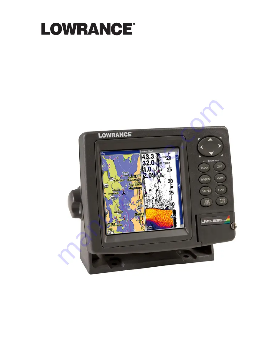
Page 247: ...nexclusive nonassignable right to use these Databases for supplemental navigation reference purposes but only as long as you comply with the terms and conditions of this License Agreement We reserve the right to terminate this license if you vio late any aspect of this License Agreement You are responsible for using official government charts and prudent navigation for safe travel 3 The Databases ...

Page 248: ...S BE LIABLE TO ANYONE FOR ANY SPECIAL CONSE QUENTIAL INCIDENTAL OR OTHER INDIRECT DAMAGE OF ANY KIND Some states do not allow the exclusion or limitation of incidental or consequen tial damages so the above limitations or exclusions may not apply to you This warranty does NOT apply in the following circumstances 1 when the product has been serviced or repaired by anyone other than us 2 when the pr...

Page 249: ...EMENT OR REFUND AS JUST DESCRIBED IS THE EXCLUSIVE REMEDY AVAILABLE TO YOU AGAINST US FOR ANY DEFECT MALFUNCTION OR NON CONFORMITY CONCERNING THE PRODUCT OR FOR ANY LOSS OR DAMAGE RESULTING FROM ANY OTHER CAUSE WHATSOEVER WE WILL NOT UNDER ANY CIRCUMSTANCES BE LIABLE TO ANYONE FOR ANY SPECIAL CONSEQUENTIAL INCIDENTAL OR OTHER INDIRECT DAMAGE OF ANY KIND Some states do not allow the exclusion or li...

Page 250: ...ange or end our ship ping policies regulations and special offers at any time We reserve the right to do so without notice in Canada If you re in Canada and you have technical return or repair questions please contact the Factory Customer Service Department Before any product can be returned you must call customer service to determine if a return is necessary Many times customer service can resolv...

Page 251: ...horization number from Customer Service Products shipped without a return authorization will not be accepted When shipping we recommend you do the following 1 Please do not ship knobs or mounting brackets with gimbal units 2 If your unit saves sonar logs or GPS data files to memory cards make sure you have saved the data to a memory card and that the card has been removed from the unit otherwise y...

Page 252: ...Visit our web site Lowrance Pub 988 0151 461 Copyright 2006 All Rights Reserved Printed in USA 120706 Lowrance Electronics Inc ...

Reviews: