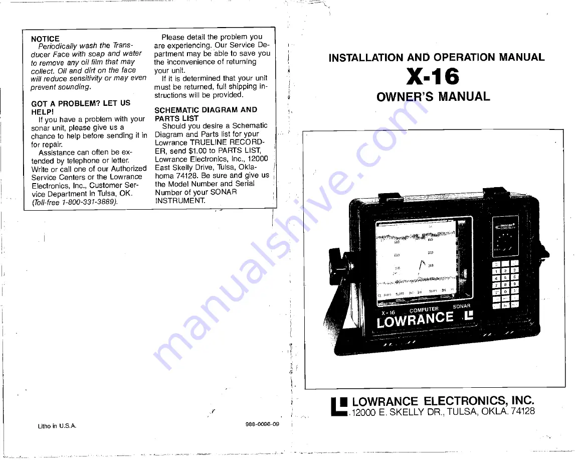
Summary of Contents for X-16

Page 1: ...ing in structions will be provided GOTA PROBLEM LET US HELP Ifyou have a problem with your sonar unit please give usa chance to helpbefore sending it in for repair Assistance can often be ex tended bytelephone or letter Write or call one of our Authorized Service Centers or the Lowrance Electronics Inc Customer Ser viceDepartment in Tulsa OK Toll free 1 800 331 3889 SCHEMATIC DIAGRAM AND PARTS LIS...

Page 2: ...nt 16 Stylus Belt Replacement 17 Maintenance 17 Troubleshooting 18 ADVANCED OPERATION 18 Surface ClarityControl SCC 18 Suppressor 19 ACCESSORIES LDT 3000 DIGITAL SURFACE TEMP Allows instant visualwadingof surface watertemperatures horn 32 0Ia 99 9degrees FIncludes heavy 28 footsensor cable DUST COVER Extra protection lromthe elements LSB 200ASWITCH BOX Allows usecitwodifferent transducers with one...

Page 3: ...s returning fromthe targets rather than a mixture of signals and noise STYLUS Thisis the fine wire that does the actual marking on a graph recorder spaper A high voltage is applied to the stylus which causesit to burn through the white outer coating ofthe paper exposing the black carbon underneath Use care when han dlingastylus Nevertouch it when the unitis operating STYLUS SKIP Thisis acondition ...

Page 4: ...lus the ability to seesmall detail is enhanced Forinstallation instructionsonthe LPB 192 read the owner s manual included with the power booster Toturnthe powerboosteron press12 2nd 5 Toturnthe powerboosteroff press2nd 8 FREQUENCY CONVERTER The Model LXC 16 frequency converter allows the X 16to use either a50 kHz or 192 kHz operating frequency at the discretion oftheoperator Itcan be switched from...

Page 5: ... if this isn t done then use crimp type splices Tape all splices with electrical tape There are two typesof noise that can be introduced intothe sonar system if an improper installation is made electrical noise picked up bythe transducer or power cable and acoustic noise picked up bythe transducer Acoustic noise is caused by water turbulence air bubbles FIGURE 2 3 passing over the transducer and c...

Page 6: ...the amount that each level slows the paper To enable the PaperSave function simply press thelevel of papersave desired then 2nd then 6 The paper should slow immediately Forexample suppose youwish to slowthe paperdown to 1 4 its present speed Press 3 2nd 6and the paperwill now be traveling four times slower than its previous speed When the Paper Save function is enabled the X 16 will print PSV and ...

Page 7: ...aper Save function is an even more powerful Thus you would usea20 degree transducer when looking for fish or strubture to easilyfind drop offs or reefs and to seefish that are around you not just below you However the 20 degree transducer won tpenetrate to greater depths as well asthe 8 degree transducer nor will it show a sharp drop off aswell In a deep water environment 100 feet or deeper or whe...

Page 8: ...e Suppressor control at any level above 3 The Suppressor control will override the automatic selec tionthat Discrimination chose If a suppression level greater than0 is selected bythe operator thenthe X 16will printan F afterthe Discrimination level For example if the Discriminationlevel is 1 and the Suppressor level is set or fixed to 3 then theX 16will print D 1 F This is areminder that some lev...

Page 9: ...olve this problem is to turn the paper speed up However Alter nate Transmit and Print or the Paper Save function listed in the Advanced Operation sectioninthis manual may help also GRAYLINE CONTROL TheGRAYLINE function can be SUPPRESSOR LEVEL INITIAL TRANSMIT PULSE INCREASE micro seconds 0 AUTOMATIC 1 0 2 100 3 200 4 330 5 450 6 600 7 800 the digital showsup on the X 16 random short lines running ...

Page 10: ...tby the operator Note Initial pulse length isthe pulselength of the unitwhenthe Suppressor control is set to minimum From 200 feetto 599 feet the initial pulse length increases atthe same rate asthe depth For example with the LOWER LIMIT setto 260 feet the initial transmit pulse length would be 260 p5 If the LOWER LIMIT issetto 390 feet the initialtransmitpulse would be 390 ps Thepulse length from...

Page 11: ...01 LOIJRAIICE 256 OFT FIGURE 13 UPPER LIMIT Many times it is desirable to expand asection of the area that is displayed on the graph recorder to show more detail This is made possible bythe X 16to show segments oftheunderwater world by using the UPPER LIMIT func tion Using the UPPER LIMIT key allows you to display any depth range at the top of the chart paper Example Turn on unitand set rangeto 20...

Page 12: ...unction will be disabled 12 0 t2 0 240 240 36 0 26 0 49 0 60 0FT 01 62 LOl RANCE 60 0 st FIGURE 38 SCC 2 SUPPRESSOR The Suppressor is a noise suppression system consisting of apatented pulselength discrimination suppression circuit It is the sameasthe one used on all Lowrance variable suppression flashers and graphs Basically it works on theprinciple that most noisepulses are of relatively short d...

Page 13: ...TheX i6 will display the depth in feet fathoms or meters Although the unit will revert back to the feet mode whenever the 2nd MARK feature is used see above it is simple to change to any mode you wish by pressing the 2nd key and then 1 forfeet 2nd 2for fathoms and 2nd 3 for meters When the unitis in the Feet mode the letters PT will be displayed next to the lower limit depth scale In the Fathom mo...

Page 14: ...o the left whilepushing the beltoff the pulleys with the other finger See Figure 37 5 Positionthe new belton the pulleys by reversingthe pro cedure used to remove the old one BE SURE the fingers of the new stylus are pointed UP 6 Close the front ofthe case Latch both catches at the top of the unit MAINTENANCE Remember the stylus may be damaged if it is infront of the platen when the transport asse...

Page 15: ...ll occurmost often whenthe Sensitivity knob is setat the point or higher Remember that there must be some movement between the boat and the fish to develop the arched mark Usually this means trolling at veryslow speeds with the main engine in gear at minimum throttle setting THERMOCLINES The temperatureof water inthe lake is seldom constant fromtop to bottom Layers of different tem peratures form ...

Page 16: ...ool 7 Slide afresh roll of Lowrance chartpaperin position on the supply side shaft on the right side of theplaten assembly The papermust spool off the bottom of the roll See Figure 30 NOTE Use Lowrance LPG 605 or LPG 606 chartpaperonly 8 Draw the end of the paper across the face of the platen around the friction roller over the take up core and tapeit squarely to the take upcore See Figure 31 Smal...

Reviews:

Related manuals for X-16