LS tractor XG3025, Operator'S Manual
The LS tractor XG3025 Operator's Manual is a vital resource for owners of this dynamic machine. Packed with detailed instructions and helpful tips, this manual ensures smooth operations and optimal performance. Download your free copy of the manual from 88.208.23.73:8080 and unlock the full potential of your LS tractor XG3025.
Share
Download


Reviews:
No comments
Related manuals for XG3025

T Series
Brand: Valtra Pages: 31
10 Series
Brand: Mahindra Pages: 120
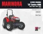
35 Series
Brand: Mahindra Pages: 368
600
Brand: Valtra Pages: 142
770
Brand: David Brown Pages: 93

2810
Brand: Mahindra Pages: 223
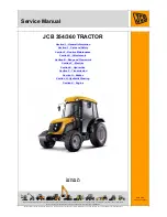
354
Brand: jcb Pages: 21

1149MT
Brand: FENDT Pages: 31

G-10
Brand: Jacobsen Pages: 54
HM600
Brand: Ransomes Pages: 134

MB7000
Brand: Nakayama Pages: 24
TC-30
Brand: Taylor-Dunn Pages: 60
5860
Brand: LANDINI Pages: 132

MAJOR
Brand: Zetor Pages: 108

4160
Brand: jcb Pages: 31
4400 BROCHURE 74-101
Brand: MASSEY FERGUSON Pages: 20
MT230E 2020
Brand: LS tractor Pages: 218

KIOTI PX1053
Brand: Daedong Pages: 256


