background image

CIB 2852

5-Button Voice Terminal

CIB 2852
Comcode 103-979-894
Issue 4

Summary of Contents for CIB 2852

Page 1: ...CIB 2852 5 Button Voice Terminal CIB 2852 Comcode 103 979 894 Issue 4 ...

Page 2: ...r button features that may be provided in your communications system FIGURE 1 5 Button Voice Terminal Assembling Your Voice Terminal 1 Unpack your voice terminal which has the following components voice terminal body handset with handset cord attached modular voice terminal cord plastic desk stand wall mount with rubber feet attached iss 4 cib2852 1 ...

Page 3: ...low for each application Runner Base Desk Support Wall Support FIGURE 2 Unassembled Desk Stand Wall Mount Desk Stand Installation 1 Break the pieces away from the runner 2 Locate the pieces labeled BASE and DESK SUPPORT File the rough edges off these pieces where they were attached to the runner 3 Insert the tabs labeled A and B on the desk support into the slots labeled A and B on the base Figure...

Page 4: ...on the stand on the voice terminal so that the stand s mounting slots fit just below the mounting tabs of the voice terminal Figure 4 Mounting Tabs Mounting Slots Stand Attached to VT Locking Tab FIGURE 4 5 Button Voice Terminal Attached to the Desk Stand Bottom View iss 4 cib2852 3 ...

Page 5: ...hat one end of the handset cord is attached to the handset If it is not plug one end into the handset now Plug the other end of the handset cord into the jack on the lower right of the voice terminal Turn the voice terminal right side up and place the handset in the cra dle Figure 5 5 Button Voice Terminal Desk Support Base FIGURE 5 5 Button Voice Terminal Attached to the Desk Stand 11 Plug the ot...

Page 6: ...lease it and slide the stand down and away from the voice terminal Wall Mount Installation 1 Break the pieces away from the runner 2 Locate the pieces labeled BASE and WALL SUPPORT File the rough edges off these pieces where they were attached to the runner Use the tip of a screwdriver to remove the four rubber feet in the corners of the bottom of the base 3 Place the base upside down on a table o...

Page 7: ...oggles for wall thickness For walls 3 8 to 1 2 thick use the smaller of the two sizes of toggles For walls 5 8 to 3 4 thick use the larger of the two sizes For solid walls either of the two sizes may be used 7 Using a 5 16 drill bit drill a hole at each of the four mounting screw locations 8 Fold and insert a toggle into each of the mounting screw locations Figure 8A Tap each toggle with a hammer ...

Page 8: ...ge the four mounting screw holes in the base Insert the top two screws into the base and partially thread the screws into the toggles Insert the two remaining screws into the lower mounting holes and tighten all four screws Figure 9 Top of Base FIGURE 9 Wall Mount Attached to Wall iss 4 cib2852 7 ...

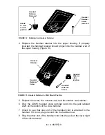
Page 9: ...0 Switchhook Button Number Card Retainer Paper Clip FIGURE 10 Removing the Number Card and Retainer 2 Remove the screw under the number card and lift out the handset retainer from the upper housing Figure 11 Handset Retainer Screw Handset Retainer FIGURE 11 Handset Retainer and Screw 3 Rotate the handset retainer 180 degrees end over end Figure 12 iss 4 cib2852 8 ...

Page 10: ...iner Screw Handset Retainer after rotation Handset Retainer Screw FIGURE 13 Handset Retainer in Wall Mount Position 5 6 7 8 Replace the screw the number card and the number card retainer Plug the D8W modular voice terminal cord into the jack labeled LINE on the bottom of the voice terminal Check to see that one end of the handset cord is attached to the handset If it is not plug one end into the h...

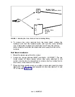
Page 11: ...ounting Tabs FIGURE 14 Attaching the Voice Terminal to the Wall Mount 11 Plug the other end of the modular voice terminal cord into the build ing wiring connection which may be a modular voice terminal jack or a modular voice terminal extension cord See Figure 6 12 To remove the voice terminal from the wall mount unplug the handset cord Set the handset aside and slide the voice terminal up and awa...

Page 12: ...this does not happen refer to the TROUBLESHOOTING TABLES in your system s Installation Guide If the problem is not resolved after troubleshooting your system contact your equipment supplier FIGURE 15 T P Switch and Volume Control Setting the Volume The volume control switch is also located on the left side of the voice ter minal Figure 15 and changes the volume of the alerting rings speaker and bu...

Page 13: ...label into the label slot above the column of touch sensitive buttons Figure 16 3 Slide the label all the way into the slot until the appropriate label is over the proper button 4 Snap the voice terminal rail back into place Rail Top Hole FIGURE 16 Removing and Inserting Button Labels To order more label strips call the toll free number for the National Parts Sales Center 1 800 222 PART The part n...

Page 14: ...olume in the earpiece A thumbwheel volume on the handset allows the volume to be turned up or down as needed The R8C3 push to listen handset 31754 is for use in noisy loca tions Like the impaired hearing handset the push to listen handset has an extra amplifier and a thumbwheel volume control It also has a pushbutton on the handset that increases the volume in the ear piece and mutes background no...

Reviews: