INSTALLATION INSTRUCTIONS
Lumascape Lighting Industries Pty Ltd
38-44 Enterprise Street, Cleveland, QLD 4163, Australia
PO Box 1875, Cleveland D.C., QLD 4163, Australia
T
07 3286 2299
F
07 3286 6599
E
sales@lumascape.com.au
W
www.lumascape.com.au
IN0039 - 19 May 2015
Copyright ©2015 Lumascape Lighting Industries Pty. Ltd. ABN 21 010 572 773
www.lumascape.com.au
Power supply must be isolated prior to connection
or disconnection of cables. Failure to do so will
result in damage to the luminaire components.
1.
Installation Preparation
To aid installation of the cable the number of elbows
and bends should be kept to a bare minimum. Also,
using 25 mm conduit is highly recommended. Check
cable length required, taking into account voltage
drop and distance to transformer. NOTE: In Australia,
each luminaire must be installed as detailed in
AS3000 Clause 6.4.4.5
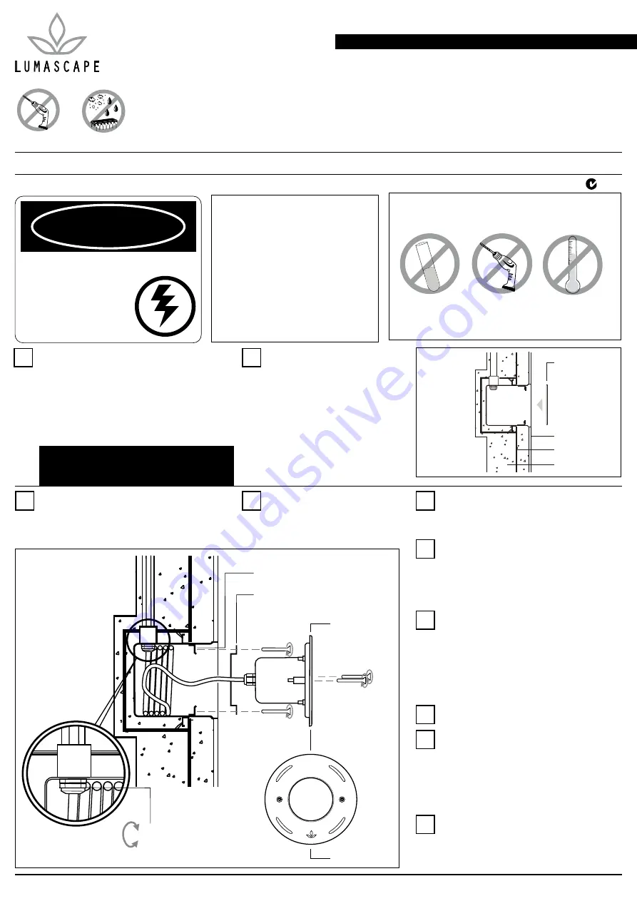
2.
Installation Preparation
Locate niche in pool and wire to
reinforcing bars.
The 20 mm conduit entry
should be at top of niche (Figure
1). Although some variation is
accommodated by the outer cover
system on the luminaire, care
should be taken to position the
niche level and to allow for pool
finishing materials.
fibreboard shield
finished surface
reinforcing bars
concrete
AVOID HIGH
CHLORINE LEVELS
NO POWER
TOOLS
WARNING
DANGER
ISOLATE LUMINAIRE FROM POWER
Failure to isolate power
supply before installation or
maintenance may result in
fire, serious injury, electric
shock, death and may
damage the luminaire.
Opening luminaire will viod warranty
The luminaire should only be used
complete with its protective
shield (cover)
Do not shorten, interfere or
disconnect cable from luminaire
Warranty will be void if cable
assembly is tampered with
WARNING
Figure 1
INSTALL AWAY FROM
OTHER HEAT SOURCES
UNDERWATER
LS333ANS-2LED & LS333AS-LED
Underwater Luminaire
Warranty void if not installed as per installation instructions
N653
MODEL LS333ANS-2LED & LS333AS-2LED
INSTALLATION TYPE Pre Install
IP RATING IP68
SUPPLY VOLTAGE 24 V DC Ripple Free Supply
12 V AC Magnetic Transformer
INSTRUCTIONS COVER Single Colour
Single Colour Dimming
RGB (Integral & Remote Driver)
NO POWER
TOOLS
KEEP ELECTRONICS FREE
FROM DIRT AND MOISTURE
tighten gland
tapped brackets
niche adjustment ring
luminaire
face plate
3.
Run Conduit & Water Proof
Connect conduit to conduit entry with suitable
conduit sealant. Use supplied adaptor if necessary.
Run the conduit to the power supply above water
level and ventilate to prevent siphoning.
7.
Terminate Luminaire
Thread cable through adjustment ring and firmly
tighten cable gland on the inside of niche to seal
cable entry (Figure 2). Connect to a suitable
power supply in accordance with local wiring
rules for connection and location of supply.
Where it is necessary to joint cables underwater
the connections and cables must be IP68 rated.
8.
Test Luminaire
Test the luminaire for correct operation.
Important Note
Do not locate luminaire near heat sources.
Chlorine levels must be kept below 4 parts per
million. Higher levels may cause corrosion to the
luminaire and void warranty.
10.
9.
Install Luminaire
Fix adjustment ring to niche with screws. Coil
free cable inside niche and install luminaire
by screwing long outer cover screws into
adjustment ring (Figure 3). Coil cable inside
luminaire with care. Do not double coils over, or
luminaire will be difficult to remove from niche.
4.
Install Temporay Shield on Niche
Fit fibreboard shield to opening of
niche before concreting (Figure 1).
Ensure no concrete enters niche.
5.
Concrete-in Niche
Encase niche and conduit in concrete. Once in
place, finish surface of pool flush with front of
niche.
6.
Concrete-in Niche
Feed cable into niche, allowing sufficient free
cable in niche to allow the luminaire to be placed
on the poolside for re-lamping and maintenance.
A maximum of 1.3 m of cable can be coiled
inside the niche.
Figure 3
Figure 2