

EOS Thru-Hull Integrated System
BEFORE YOU START
www.Lumishore.com
45-0057-REV-3
Lumishore UK Unit 3, Technium 1, Kings Road, Swansea, SA1 8PH, UK | +44(0)208 144 1694 | Info@Lumishore.com
Lumishore USA 7137 24TH Court East Sarasota, Florida 34234 | (941) 405-3302 | Sales@LumishoreUSA.com
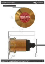
TIX 802 & TIX 1602 Thru-Hull Light
Lumishore EOS Full Colour Change light
Installation and Operating Guide
Congratulations! You have purchased a LUMISHORE advanced technology underwater light. Every care has been
taken to ensure your Thru-Hull light arrives in perfect condition, so please enjoy the ultimate experience in
underwater lighting.
LUMISHORE Thru-Hull high intensity lights are designed for those owners who prefer the integrity of a thru-hull
installation in a light that employs the most powerful, efficient and cost effective underwater LED lighting on
the market today. The LUMISHORE Thru-Hull is suitable for many sizes and types of watercraft, including Sports
Boats, Cruisers, Yachts and Super Yachts. LUMISHORE Thru-Hull LED lights come with a compact electronic driver
module to ensure trouble free operation for years to come.
Please read the following pages before attempting installation to ensure complete understanding of
the LUMISHORE LED lights.
• High Intensity LED light – Do not stare into the LED module at close proximity.
• Always ensure that the vessel’s power source and battery are disconnected or isolated prior to installation
• A qualified professional should carry out both the electrical and mechanical installation. If in doubt please contact LUMISHORE;
Refer to product support section
• Always use a suitable fuse or circuit breaker to protect the complete system. Each light to be individually fused.
• The Thru-Hull maybe installed into GRP (Glass Reinforced Plastic or Fibreglass) and wooden hulls.
• For metal hull or carbon fibre installations an isolation kit will be required.
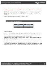
• The light should be installed 6” - 10” (150-250mm) below the minimum load waterline.
• For best results install the lights between 2.5ft (0.8m) and 6.5ft (2m) apart.
• Never try to install or remove light with the vessel in the water.
• Lights should not be exposed to any temperatures in excess of 150°F (65°C). For example, next to hot engine components or
where exhaust emissions could be expelled onto the light while underwater.
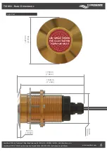
• Do not over tighten the retaining bolts. A force of
3Nm
on each bolt should not be exceeded.
• All LUMISHORE products should have a bonding to the DC system via bonding strap for galvanic protection.
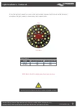
• Choose a location - The light must be installed onto a flat (not curved) surface. Mount on transom or side hull only.
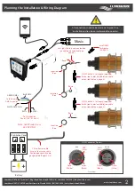
The following components should be used;
• Fuse (1 per light)
• Waterproof junction box
• Power Relay
• EOS Controller
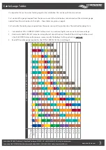
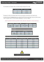
• Power cable - See cable gauge
guide for more information
• Power Switch
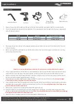
The following tools will be required;
• Hand Drill
• Screwdriver (Cross head)
• Appropriate Sealant (e.g. 3M 4200)
• Cleaning rags
• Holesaw - Refer to holesaw size on
page 8
1


