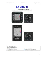
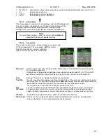
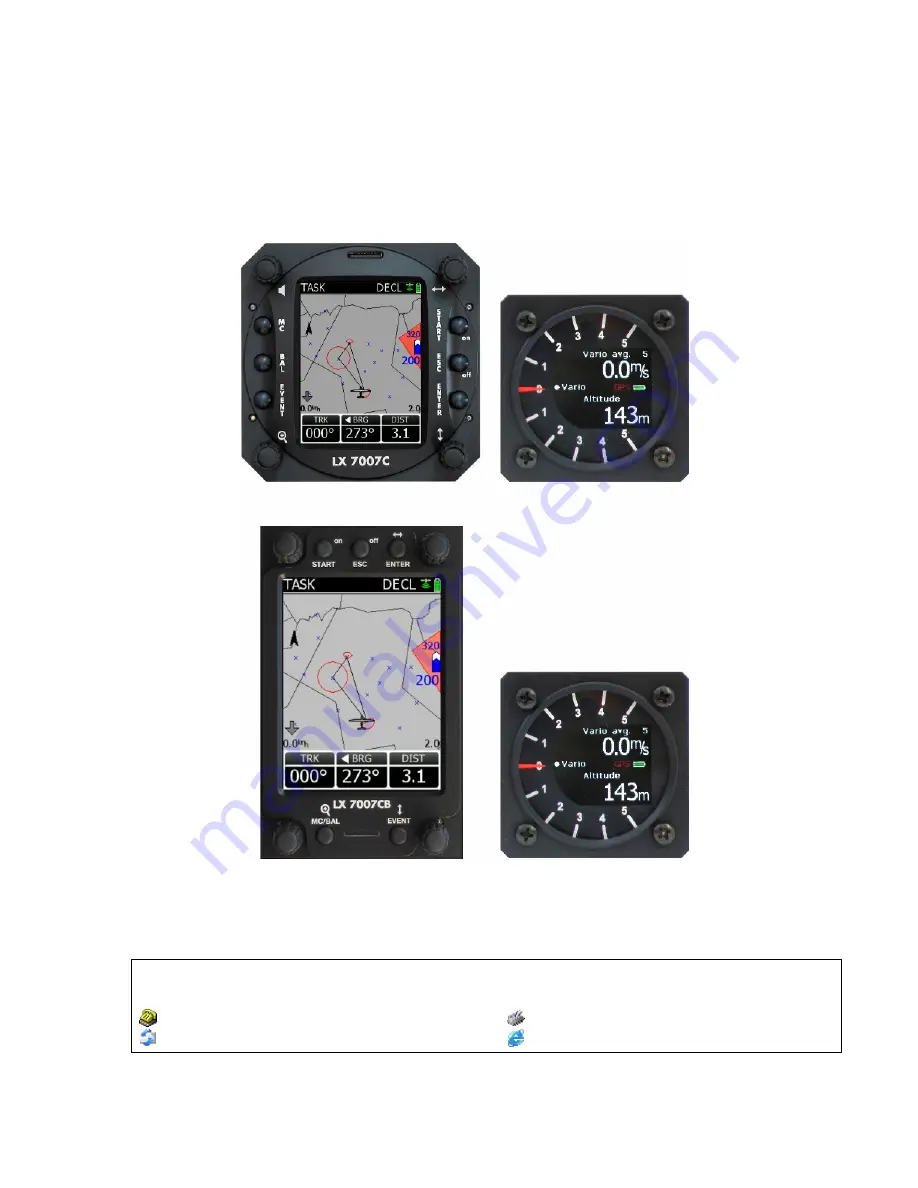
background image

LX Navigation d.o.o.                              LX 7007 C                                          May. 30th 2012 


- 1 - 


LX 7007 C 


Users manual V 3.0  


(Also valid for LX 7007 CB and LX 7007 Compact C/CB) 


LX 

navigation


d.o.o.


Tkalska 10 SLO 3000 Celje  

 + 386 3 490 46 70               


 + 386 3 490 46 71 

 support

@

lxnavigation.si    

  http://www.lxnavigation.si


Summary of Contents for LX 7007 C

Page 1: ...07 C May 30th 2012 1 LX 7007 C Users manual V 3 0 Also valid for LX 7007 CB and LX 7007 Compact C CB LX navigation d o o Tkalska 10 SLO 3000 Celje 386 3 490 46 70 386 3 490 46 71 support lxnavigation si http www lxnavigation si ...

Page 2: ...el 11 2 3 1 1 QNH RES QNH and Safety Altitude input 11 2 3 1 2 PILOT 12 2 3 1 3 LOGGER Input of flight recorder parameters 12 2 3 1 4 TRANSFER 14 2 3 2 SYSTEM SETUP Second level 15 2 3 2 1 Glider 15 2 3 2 2 Airspace Selection of airspace section and warning criteria 15 2 3 2 3 AUDIO Vario Adjustment of audio 15 2 3 2 4 Audio Alarm 16 2 3 2 5 Turn points 16 2 3 2 6 Task Observation Zone 17 2 3 2 7 ...

Page 3: ... 33 3 1 1 Single pilot option 33 3 1 2 Multipilot option 33 3 1 3 SET Elevation take off elevation input 33 3 1 4 Preparation of data base 34 3 1 5 Preflight check 34 3 1 6 Preparing a task 34 3 1 6 1 AAT assigned area task 34 3 1 7 Task Start 35 3 2 Flying a task 35 3 2 1 Flying a speed task 35 3 2 2 Flying an AAT 35 3 2 2 1 Start 35 3 2 2 2 Inside AAT sector 35 3 3 Flarm functions 36 3 3 1 Traff...

Page 4: ...LX Navigation d o o LX 7007 C May 30th 2012 4 4 8 46 4 8 1 Wiring LX 7007 Compact C 46 4 8 1 1 GPS connection 47 4 8 2 Wiring LX 7007 Compact C B 47 4 8 2 1 GPS connection 47 ...

Page 5: ...io unit The Vario unit display consists of a mechanical needle which is mainly used as vario indicator and a colour graphic display which is configurable in setup LX 7007 C LX 7007 CB The unit comes in two versions LX 7007 C can be fitted into 80 mm standard cut out and LX 7007 CB has a bigger 3 5 inch display which requires a larger cut out The functions of both units are identical Vario function...

Page 6: ... for data transfer and firmware update IGC interface to connect and power Colibri or LX 20 The connector pin out corresponds to the IGC standard and may be used to power the LX 7007 and to communicate with PC also by the use of a standard Colibri Power adaptor Whilst training this input can be used to connect to Condor flight simulator Options Integral Flarm collision avoidance system Remote contr...

Page 7: ...sed for instance as PTT for radio and SC Vario changeover command Using a two seat configuration two remote units can be installed to control the front and rear seats separately 1 2 3 Flarm Flarm electronics is completely compatible to original Flarm units and an integral part of LX 7007 C DU if ordered as an option All necessary connectors are available at the back of the unit Flarm update port F...

Page 8: ...oint in Task mode but only if the glider is inside the TP sector This is only valid if the changeover preset has been set to not automatic In TP a short press will start storing of present position to become a new turn point During edit a short press on Start will move cursor one step back The unit is equipped with a facility of storing up to 100 pilot names Pilot selection can be done by rotating...

Page 9: ...is a multifunctional key which has two main functions If it is pressed and held for a few seconds then the instrument will start turning OFF sequence A count down will show time in seconds until the unit will switch off A new press on any key during count down will interrupt switching off process If a short press is made then the button has the following functions The display will jump to the menu...

Page 10: ...rport select one airport or land able turn point no further inputs are possible APT Navigation and selection of airports TP Navigation selection and editing of turn points TSK Navigation selection and editing of tasks STAT Flight statistics and logbook SETUP has two levels The first level enables direct input of individual parameters By entering into SYSTEM SETUP global parameters can be adjusted ...

Page 11: ... required to change QNH ALT R Press ENTER Use UP DOWN to select the value required and press ENTER to input it Once all changes are complete press ESC top return to SETUP menu ALT R This setting is used to input the altitude reserve or safety altitude Setting 0 means that no altitude reserve is set for the final glide After input the final glide is shifted and the arrival is calculated to the alti...

Page 12: ...unction then the function will not affect other pilots For future a pilot list transfer file transfer via SD card is foreseen 2 3 1 3 LOGGER Input of flight recorder parameters The flight recorder is fully approved by the IGC A sub committee of the FAI and will produce secure flight records that are acceptable for all kind of FAI badge flights and also world records After selecting LOGGER and pres...

Page 13: ...ons by which the instrument is switched between vario and speed command OFF Switching is possible exclusively by an external switch connected to the LX 7007 AU or USB unit GPS When the GPS detects that the glider is circling an automatic change over to vario mode will happen after approximately 10 seconds Detection of straight flight will cause a change to speed command IAS When the IAS exceeds a ...

Page 14: ...es format should be cup airspace cub and airports in af format Flight info pilot and declaration should be in hdr LX navigation format Item FlarmNet which is positioned below Airport icon can be used for input of Flarm IDs This makes possible to recognize Flarm objects under their custom names The file is available on http www flarmnet org Download LX Navigation variant Structure of LX folder in w...

Page 15: ...ored airspace sections Select section of interest by Up Down Input of Warning Yes will produce an audio warning close to the airspace See also chapter Graphic Appearance Note LX 7007 C is able to use only one airspace section at the same time the section should be enabled in Airspace menu of System Setup also during the flight Creation of custom airspace files To prepare custom airspace in CUB for...

Page 16: ...TPs or APTs detected as inside Near rad will be taken as part of a task Not active at the moment Sort defining TP sort criteria alphabet and distance are offered Task file the unit is capable of managing up to three turn point files at the same time combining the points of all three files If a turn point file activated as Task file includes also task data those tasks will be available for navigati...

Page 17: ...l settings and will affect all tasks which are stored in memory Local sector adjustment is possible in task edit zone of Task navigation menu 2 3 2 7 Graphics The graphic display of the LX 7007 C can show a lot of information and if it is all selected the display can become very cluttered This particularly applies to airspace information and the user should ensure that only relevant airspace is se...

Page 18: ...on enter and a list of all near airspace sections will open Upper two places are reserved for the sections which caused warnings Allocation of colours To every AS class and type a colour black yellow red or grey can be allocated after using of appearance Menu of Graphics Fill command can be executed only on CTRs and Restricted areas Allocation of colours Fill option Example NO Fill Meaning of figu...

Page 19: ... recommended to use TEF 4 Electronic TE is only effective when the pitot and static sources are co located and the pneumatic lines to the instrument are approximately the same length The best sensor to use is the combined pitot static Prandtl tube If problems are experienced with the electronic TE compensation then the most likely cause is the glider s static source The static source can be checke...

Page 20: ...ators Secondary indicators should be connected via 485 system bus There are three 9P connectors at the back of the unit All contacts are absolutely parallel so it doesn t matter which one is occupied The unit can be also used as 485 system bus splitter To define Ind number use DIP switches which you find at the back of the unit After indicator functions have been defined switch the unit off and th...

Page 21: ...cked items means active function and vice versa Flarm part is relevant only if the unit is equipped with Flarm option 2 3 2 13 Flarm Item Flarm is only active with units which are equipped with Flarm module The upper four rows are information only the last two rows enable inputs Region input will adjust frequency relating to the area of operation Privacy Yes will reduce the data which is sent so t...

Page 22: ...CB Setting makes it possible to adjust LX 7007 baud rate to meet GPS source baud rate Possible settings are 4800 9600 19200 38400 bps 2 3 2 18 ENL Engine noise level This page allows no input the bar shows ENL figure And can be used only to check that the ENL is working properly 2 3 2 19 Hardware Any additional bus participant as Rear seat unit Remote controls or compass should be enabled in this ...

Page 23: ...ent after Update menu will open select Upgrade function and press Enter verifying process will start this is not update input PW which you find above you have to input all positions if PW is shorter than go on by Enter until update bar will start Final check check program version during next booting pay attention on date Important Use the same file also for the update of second seat units and also...

Page 24: ...ctor Page with satellite status is available only for units without Flarm 2 4 2 NEAR AIRPORT This option displays the nearest airports from the APT database and also from the TP list Only turn points having an attribute land able are included The airports are sorted by distance with the closest first Simply place the cursor with the UP DOWN selector on the desired airport and press ENTER The LX 70...

Page 25: ...2 4 3 1 APT TP Navigation sub pages First sub page brings navigation data and also some gliding relevant data in numeric form The information may vary dependant upon whether climbing or in straight flight Averager is replaced with Netto during strait flight Steering command is placed near track indicator Explanation of terms 1st sub page BRG bearing towards selected point DIS distance to TP APT TR...

Page 26: ...ocal time ETE estimate time elapsed GS ground speed ETA estimate time of arrival Frequency airport frequency Runway runway direction AOT and Battrey voltage are displayed in the bottom row of the display Not available for non land able turn points Explanation of terms 3rd sub page This is an info page and can be used after a position report to ATC is required Three is no alternate data QFE informa...

Page 27: ... data in LX 7007 C memory First is called User USR xx and there are stored tasks created by hand Maximum 70 tasks Second store is built of tasks which are included in TP file which is activated as Task File in Turn point menu of System Setup Such tasks are called Imported IMP xx Capacity of imported store is limited to 20 tasks if the file consists of more tasks only first 20 will be useable Impor...

Page 28: ...s been used the actual task data will be copied into DECL task Declared Task update during flight is possible but the action will not change declaration in Flight recorder as IGC rules do not allow updates during flight General rule if you find DECL designator in the task right upper corner you are sure that the task is regularly declared Designations IMP or USR show a not declared task Understand...

Page 29: ...ening time Before start input of altitude and time limit before start Start conditions input of start conditions QNH based input should be done More about task start see in capture Flying Note If any start parameter will be out of limits during start line crossing this will not prevent task start All mentioned is for information purpose only A forced start is possible at any time after a long pres...

Page 30: ...e actual time and duration of actual flight are displayed 2 4 5 2 Task statistics This kind of statistics data is available exclusively after a task has been started and the switch rotated clockwise the task statistics data become available Left column describes task data and right column actual leg data Explanation of terms Tspd Task speed Dist flown Distance Dur time spent on task on leg Avg var...

Page 31: ...d to a good static pressure source If pneumatic compensation is selected then the TE Pst port should be connected to the TE probe Compensation with TE probe Electronic compensation 2 5 1 Smart Vario description The LX system incorporates two configurable electronic filters in the circuitry The first filter adjusts the time constant and is adjustable between 0 5 and 5 seconds The 0 5 setting is the...

Page 32: ...mum 5 minutes off Download the last flight and print the barogram using the Lxe PC program Restore flight recorder settings The barogram will be the last flight in the logbook 2 5 3 Speed command Speed command flying based on the McReady theory is a very useful tool to optimise cross country speed There are many ways of visual indicators When the instrument changes to speed command mode the audio ...

Page 33: ...nd switch automatically to the Set Elevation page Don t confirm SAVE TO PILOT LIST with Y 3 1 2 Multipilot option If more pilots are intending to fly the same glider their names Can be input after editing of an existing pilot name After any change a very typical message Create a new pilot will appear on the screen After Yes the new pilot will be stored Some system settings are connected to the pil...

Page 34: ...ined with set in setup LOAD 3 1 6 Preparing a task While it is advisable to prepare the task correctly before taking off and thus avoid mistakes made in haste all the following actions with the exception of a FAI Declaration can also be done during flight a Entering the task Transfer the task file CUP after use of an SD card Activate a new file in System setup Turn points if necessary Edit a simil...

Page 35: ...rohibit start The start will be executed as normal even by presence of warning Warning is only for information Task restart is possible at any time After restart the task will change over into ARM status automatically After a turn point was confirmed and there is a need to continue in the sector a Leg restart is offered 3 2 Flying a task The most important tip is to prepare the task which is inten...

Page 36: ...int All statistics data will change regarding to the new fact 3 3 Flarm functions Units equipped with Flarm module which is an integral part of the instrument offers plenty traffic information features Note Using the Flarm functions which are available on LX 7007 C graphic display doesn t suspend the use of Flarm external indicator There are two displays which show Flarm data on LX 7007 Flarm obje...

Page 37: ...th Flarm display alarm status Commands Zoom change range from 500 m to 10km select object which will be observed in more detail Use ESC to leave Flarm radar Info Boxes LX 7007 Flarm radar has the capability to show detailed data of two close gliders Mark Info box by use of press Enter and rotate Data shown in info box Flarm ID Vario relative altitude distance Note Sometimes the arrows change into ...

Page 38: ... can be displayed at the same time and are therefore numbered as 1 and 2 Red coloured dots shows more critic situation Situation low level warning horizontal outside vertical inside High level warning inside situation I Combination of low level and high level warnings AS warning dots are present also in the second navigation page to inform the pilot about possibility of airspace violation Note Set...

Page 39: ...pen a list of all airspace sections which are close to the glider The pilot is now able to select some restrictions or to disable particular airspace permanently After any restriction the airspace will get a red attribute but will remain on the list Any disabled airspace can be enabled at any time Upper two sections are reserved for detailed airspace data of airspace sections which have caused war...

Page 40: ...7007 PRO IGC You can now see the mounting screws While holding the knobs slacken the screws with a screwdriver Now the knobs can be removed never use power to remove the knobs you can damage rotary switches By problems hit on the slacken screw a little bit Remove the four special type screws Position the LX 7007 PRO IGC in the cut out in the instrument panel Tighten the LX 7007 PRO IGC with the sp...

Page 41: ...ed to the back of the vario unit A label shows their functions Ptot Pitot or Total pressure TE TE probe Pst Static Electronic TE compensation schematics Set TE 100 TE Pst Static Pst Static Ptot Pitot or Total pressure instrument panel selector axis press in cover special type screw rotary knob LX5000 LX7007 ...

Page 42: ...f both units are connected correctly before first power on The power wires red and blue should be connected to the 80mm unit Note There is no fuse in the instrument so it is VERY IMPORTANT to use an external fuse max 3A Power supply cables should use a minimum of 0 5mm wires 20 avg To prevent damage to the LX 7007 80mm unit after a short on 485 bus a fuse of blade type the same fuses that are used...

Page 43: ...ton Set this after using of LX Remote 4 6 Installation of PDA units LX navigation offers a wide range of accessories which makes the installation of a PDA in conjunction with LX 7007 extremely easy and completely plug and play LX 7007 has a separate com port specially designed to drive PDA 5V power for PDA is included Using of LX standard cables is possible to connect practically all iPAQ units to...

Page 44: ...5 system bus by use of 485 Splitting units Installation of all options is plug and_play and therefore requires only mechanical installation work LX 7007 C DU also powers all bus connected devices A fuse built on LX 7007 C DU back prevents damage to the DU after a short in wiring or in some 485 device will happen Note Never connect devices to 485 bus if LX 7007 C DU is under power 485 First seat Se...

Page 45: ...LX Navigation d o o LX 7007 C May 30th 2012 45 4 8 Wiring schematics also valid for LX 7007 Compact CB ...

Page 46: ...d on the back side of the unit Inputs and outputs are already wired and also clearly marked PDA output delivers 5V to supply PDA unit and offers also Tx and Rx lines A four terminal connector offers a so called open wire solution Cables for PDA units and also LX Mini map are available as options 1 2 3 4 5 6 7 8 9 10 11 12 13 14 15 16 17 18 19 20 21 22 23 24 GND 12V VARIO INDICATOR Speaker OAT PDA ...

Page 47: ...g and play via 6P 6P telephone type cable with two twisted wires one cable is part of delivery 12 V included original Flarm units should be connected via main connector 8P and not via 6P connector Colibri II Colibri II power and data adapter plus 6P P cable with twisted wires one cable is part of delivery 4 8 2 Wiring LX 7007 Compact C B The unit has standard LX 7007 C connector layout the same is...

Reviews: