background image

Aviation Products

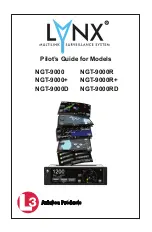
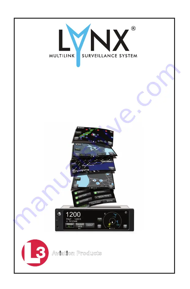
NGT-9000

NGT-9000+

NGT-9000D

Pilot’s Guide for Models

NGT-9000R

NGT-9000R+

NGT-9000RD

Summary of Contents for 9029000-20000

Page 1: ...Aviation Products NGT 9000 NGT 9000 NGT 9000D Pilot s Guide for Models NGT 9000R NGT 9000R NGT 9000RD...

Page 2: ...splays other ADS B equipped aircraft and transponder equipped aircraft via TIS B is only for pilot situational awareness This equipment is not approved as a collision avoidance tool Any deviation from...

Page 3: ...emote mount Document Part No 0040 17000 01 Revision C Copyright 2015 ACSS Refer to the following for additional copyright information https www l 3avionics com open source aspx https www l 3avionics c...

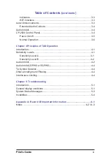
Page 4: ...able Configuration Module DCM 1 14 Directional Antenna 1 15 Alternate Displays 1 15 Personal Electronic Device PED 1 15 WiFi Serial Adapter 1 15 CP 2500 Control Panel 1 15 Chapter 2 Operation Introduc...

Page 5: ...Options Screen 2 19 Options Status 2 19 Options Settings 2 20 Selected Traffic Button i 2 21 Traffic Information Window 2 21 TIS B No Coverage Indicator 2 21 Selected Traffic ID 2 22 Selected Traffic...

Page 6: ...Selection 2 34 FIS B Textual Application 2 35 Display Area 2 35 Banner 2 35 Traffic Button 2 35 Airport Button 2 36 Edit Airport ID Window 2 36 Favorites Button 2 37 Favorites Pick List Window 2 37 Pr...

Page 7: ...duction 4 1 Sensitivity Levels 4 1 Sensitivity Level A 4 1 Sensitivity Level B 4 2 Audio Inhibit 4 2 Audio Inhibit GPWS or EGPWS 4 4 TA Symbol Duration 4 4 Other aircraft ground Filtering 4 4 Interfer...

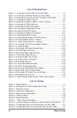
Page 8: ...2 15 On Off Options Screen 2 28 Figure 2 16 Weather Map Legend Screen 2 29 Figure 2 17 Declutter Option Screen 2 30 Figure 2 18 Weather Map Text Screen 2 31 Figure 2 19 Product Pick List Window 2 32 F...

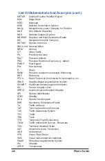
Page 9: ...Document EAR Export Administration Regulations EGPWS Enhanced Ground Proximity Warning System FAA Federal Aviation Administration FDE Fault Detection and Exclusion FIS B Flight Information Service Bro...

Page 10: ...IM Receiver Autonomous Integrity Monitoring REF Reference RTCA Radio Technical Commission for Aeronautics Inc SBAS Satellite Based Augmentation System SIGMET Significant Meteorological Information SIL...

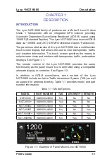
Page 11: ...sponder traffic and weather displays See Figure 1 1 The remote version of the Lynx NGT 9000 provides the same functionality as the panel mount but is controlled using a compatible alternate display or...

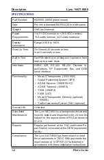
Page 12: ...al interface Functionality Mode S Transponder 1030 1090 Global Positioning System GPS ADS B Receive 1090ES UAT ADS B Transmit 1090ES TIS B 1090ES FIS B UAT Mode S Transponder Diversity optional 1090ES...

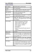
Page 13: ...S Transponder 1030 1090 Global Positioning System GPS ADS B Receive 1090ES UAT ADS B Transmit 1090ES TIS B 1090ES FIS B UAT Mode S Transponder Diversity optional 1090ES Traffic Awareness System TAS o...

Page 14: ...ery second The TIS B system currently only sees transponder equipped aircraft No transponder no TIS B other aircraft Always look outside Pilots flying in visual meteorological conditions VMC are remin...

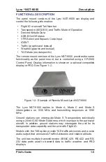
Page 15: ...n is shown on a optional compatible display or PED See Figure 1 2 Figure 1 2 Example of Remote Mount Lynx NGT 9000 The Lynx NGT 9000 replies to Mode A Mode C and Mode S interrogations on 1030 MHz and...

Page 16: ...The Traffic Awareness System TAS option provides the system the capability to interrogate nearby aircraft transponders and issue Traffic Advisory TA alert to the flight crew This option requires the...

Page 17: ...ds on the surface 5 seconds in the terminal area and 10 seconds in the en route airspace Other aircraft are provided by the ground station if within a 15 nm horizontal range and 5 000 ft of altitude o...

Page 18: ...itude of the receiving aircraft ADS B equipped ground aircraft and vehicles are not displayed to airborne aircraft Aircraft not equipped with a transponder or equipped with a Mode A only transponder a...

Page 19: ...UAT 1090ES TAS Traffic 70 nm TAS 10000 TAS 3500 ft TIS B Own Aircraft UAT 1090ES TAS model option 5000 ADS R 30 nm TIS B ADS R ATC Ground Station Other Aircraft UAT Non Equipped Mode A C Equipped TIS...

Page 20: ...pilot in the visual acquisition of aircraft that may represent a danger Traffic information out to a selected range is graphically displayed on the NGT 9000 or alternate display The system display sho...

Page 21: ...focused on avoiding areas of inclement weather that are beyond visual range or where poor visibility precludes visual acquisition of inclement weather FIS B weather and National Airspace System NAS st...

Page 22: ...ayed in a mosaic map which shows patterns of precipita tion and its movement The Regional NEXRAD FIS B product is a composite of available NEXRAD radar imagery in a local area showing a more detailed...

Page 23: ...less of the size of the area TAF Terminal Aerodrome Forecast is a format for report ing aviation weather forecast information Generally a TAF is a 9 or 12 hour forecast though some TAFs can cover an 1...

Page 24: ...tion and Satellite Based Augmentation Systems SBAS The Lynx NGT 9000 have an internal GPS function that provides position velocity time and integrity NIC NAC etc informa tion to the ADS B functions Th...

Page 25: ...al electronic devices e g tablets via a WiFi connection The PED must use compatible applications that support the ADS B broadcast services i e ADS B In TIS B ADS R and FIS B Check with an avionics dea...

Page 26: ...Lynx NGT 9000 Pilot s Guide 1 16 Description Page intentionally blank...

Page 27: ...witch to apply power Normal operation begins within 10 seconds of applying power During start up the unit checks for valid configuration data and initializes self tests The GPS begins initializing If...

Page 28: ...t transitions to normal operation within 5 seconds bypassing the splash version and flight ID screens Splash Screen The splash screen is displayed in less than 5 seconds after power is applied The com...

Page 29: ...led is heard through the aircraft audio system The option to restart the unit or to continue start up in a degraded mode is shown on the right side of the display Tap the Restart button to restart the...

Page 30: ...ID The Flight ID Number is entered using the keypad The keypad will change to numbers after three alpha characters are entered When complete tap the Done button to proceed to normal operation The las...

Page 31: ...e touch screen display is divided into left and right screens that show information specific to the selected application The user can select input and adjust information on the screen using buttons ed...

Page 32: ...Used to increase or decrease the display brightness level Tap the button to open a slide bar Not Selected Selected Scroll Bar The scroll bar is used to navigate vertically through a list or block of...

Page 33: ...he message text Self Test Failures Occured Self Test Failures Occured Restart Continue Message Text Function Activate Buttons Table 2 1 Button Functions continued Application Screens The display is di...

Page 34: ...s of AC 20 172A and DO 317A for the purpose of supporting the Enhanced Visual Acquisition EVAcq and Basic Airborne AIRB CDTI applications FIS B Graphic Simplified moving map display with depiction of...

Page 35: ...the Squawk Code Edit Screen is shown See Figure 2 6 The current Squawk Code continues to be transmitted until the last digit of the new Squawk Code is entered The edit mode is cancelled by tapping the...

Page 36: ...inATC modeAin which it replies to interrogations but does not report the plane s altitude Selecting ALT put the transponder in ATC mode C When the aircraft is In Air the transponder replies to interr...

Page 37: ...e previously viewed screen Refer to the Chap 5 Troubleshooting for corrective actions ON GND Indicator The ON GND indicator provides the pilot a notification that the transponder is operating in the o...

Page 38: ...for any of the system functions then the message Service Unit Soon is shown on the right side of the display Tap Continue screen button to proceed Correct failures before going any further with the fu...

Page 39: ...awareness This functionality does not relieve the pilot of see and avoid responsibilities as described in 14 CFR 91 113b Traffic information shown on the Lynx NGT 9000 is dependent on other aircraft h...

Page 40: ...directional data for intruder aircraft are shown as diamonds A solid amber circle or with a black filled arrowhead is a Traffic Advisory TA that represents an intruder aircraft that may pose a collisi...

Page 41: ...ge TA displays the relative altitude of the intruder regardless of the current vertical display mode Only display data tags for altitude reporting aircraft are shown Non altitude reporting aircraft ar...

Page 42: ...und Vehicle Directional On Ground Non directional OT Ground Vehicle Non directional 01 Airborne Directional TA Traffic symbol with a data tag indicating a relative altitude of 100ft below with a horiz...

Page 43: ...ranges are in relation to the ownship A description of each mode is detailed below Normal NRM Traffic is displayed from altitudes of between 2 700 and 2 700 ft This mode is typically used during the...

Page 44: ...d at the top of the left screen with the following information Quick return button is labeled XPDR and is used to return to the Transponder Application screen Mode A squawk code Reply R or Ident ID in...

Page 45: ...button opens a screen showing GPS satellite information The Settings button opens a screen allowing the setting of Initial Traffic Altitude Mode VFR Squawk Code Display Brightness Trim and Flight ID...

Page 46: ...available for the GPS data a white dash is inserted Options Settings TheSettingsscreenprovidesthefollowinginformationandfunctionality See Figure 2 11 Radio buttons to set the traffic altitude mode Nor...

Page 47: ...iled not in standby Traffic Information Window The window is shown over the traffic screen and provides the following data and functionality Flight ID of the selected aircraft Emitter Category or type...

Page 48: ...elected Traffic GS if configured appears along the right side of both screens under the selected traffic ID after a traffic symbol is pressed The Traffic GS is removed when the selected traffic symbol...

Page 49: ...north up Figure 2 13 Weather Map FIS B Graphical Weather Application The Graphical Weather Application is located in the second screen position as indicated by the Application Indicator The Graphic Ap...

Page 50: ...n received are indicated using a gray semi transparent graphical overlay This will cause land masses to appear grey and water to appear light blue Country and State borders are solid light gray lines...

Page 51: ...Towered Soft Surfaced Airport Non towered Soft Surfaced Airports Towered Hard Surfaced Small Airports 1 500 to 8 069 ft runway Non towered Hard Surfaced Small Airports 1 500 to 8 069 ft runway Towered...

Page 52: ...pitation winds and visual obstructions The type and graphic description are detailed below NEXRAD Map Elements NEXRAD provides data on precipitation and its intensity in the form of a composite mosaic...

Page 53: ...te the panning function North Indicator This indication is a white green arrow located in the lower right corner of the display The indicator points to the top of the display when the application is o...

Page 54: ...On See Figure 2 15 Weather Map Legend Screen The Legend screen is located on the left screen and is shown after the Legend button in the On Off screen is tapped The screen has a banner on the top of...

Page 55: ...Lynx NGT 9000 Pilot s Guide 2 29 Operation Figure 2 16 Weather Map Legend Screen...

Page 56: ...nner at the top of the screen that is labeled with the declutter range scale from 10 to 800 The Declutter setting sets the zoom range when a product is displayed removed from the display The display a...

Page 57: ...button opens a Product Select window The button is displayed only when the selected display element is an airport See Figure 2 19 If selected product text data report is not available the display are...

Page 58: ...ayed on the Weather Map Text screen If data for that product type is not available the message not available is displayed Figure 2 19 Product Pick List Window FIS B Graphic Winds Temp Application The...

Page 59: ...n This button is located on the far left side of the screen and is labeled TFC with a left facing triangle Tap the button to return to the Traffic Application screen The winds aloft display properties...

Page 60: ...icator is located at the bottom of the screen and is shown with green text when a valid time is shown The text is shown with yellow text when the data is not valid or available Ownship Symbol The owns...

Page 61: ...how text report data from the selected Product Figure 2 22 FIS B Textual Application Banner The banner is located above the display area The banner contains buttons to return to the Traffic Applicatio...

Page 62: ...enter the three or four character alpha numeric Airport ID in the airport edit box Tap the Cancel button to close the window without changing the current Airport ID Tap the Add to Favorites button st...

Page 63: ...t is centered in the display area showing the list of airports set by the user via the add to favorite button located in Edit Airport ID window The list has a maximum 50 entries organized alphabetical...

Page 64: ...the window and set the Product If selected product text data report is not available the display area indicates this by displaying the selected product with a not available message Maintenance Mode M...

Page 65: ...be completed within 15 seconds or the Calibration Time out message is shown The unit returns to the main screen If normal operation is desired cycle power to the unit or tap the Reboot text on the ma...

Page 66: ...Lynx NGT 9000 Pilot s Guide 2 40 Operation Page intentionally blank...

Page 67: ...t In Coverage The blue lamp illuminates when there is not a ground station within range ADS B Out Fail The amber lamp illuminates if the unit is unable to transmit when ADS B GPS has failed or if the...

Page 68: ...presents an intruder aircraft that has been detected within the selected display range and vertical display mode but which has not generated a TA or a PA The symbol is white or cyan on color alternate...

Page 69: ...ouncement will not be heard if audio is inhibited It may also be delayed if a higher priority alert is occurring at the time of the alert Do not rely solely on the aural alerts for intruder aircraft i...

Page 70: ...affic 10 O clock high 5 miles This aural announcement is for an intruder at a relative bearing of 300 degrees at a higher altitude 5 miles away Traffic Traffic 6 O clock same altitude less than a mile...

Page 71: ...scrolling of the Firmware and hardware levels of the CP 2500 approximately 15 seconds The unit then reverts to normal operation If the self test fails the unit displays Failed and the unit does not r...

Page 72: ...ATC The VFR button sets the squawk code to a programmed VFR code that is set in the menu Typically it is set to 1200 in the United States Pressing the button again returns the code to the previous sq...

Page 73: ...ition input is not functioning IDENT The IDENT message is being sent by the Lynx NGT 9000 via ADS B Out GPS INIT GPS Initialization The GPS contained within the Lynx NGT 9000 is not ready NO ADS B COV...

Page 74: ...Lynx NGT 9000 Pilot s Guide 3 8 Controls and Indicators Page intentionally blank...

Page 75: ...phase of flight sensitivity level B Sensitivity Level A Sensitivity level A consists of two criteria for displaying a TA The intruder aircraft enters into an area of airspace surrounding ownship defi...

Page 76: ...i horizontal radius and a height of 800 ft from ownship The intruder aircraft approaches ownship on a course that intercepts ownship within 20 or 30 seconds within 20 seconds for a non altitude report...

Page 77: ...ius and a 600 ft relative altitude 6 Within 15 20 sec of CPA 7 Up Within a 0 55 nmi horizon tal radius and a 800 ft relative altitude 8 Within 20 30 sec of CPA 9 Fixed Not available Within a 0 55 nmi...

Page 78: ...g To assure that interference effects from active TAS equipment are kept to a minimum the FAA requires TAS equipment to interference limit i e reduce its transmit power when it is operating in congest...

Page 79: ...0 ft 20 seconds for non altitude reporting intruder aircraft TAS Only Unrestricted UNR 9900ft Up to 35 nmi 4 nmi Traffic Advisory TA airborne Non directional Proximity Advisory PA airborne Non direct...

Page 80: ...Lynx NGT 9000 Pilot s Guide 4 6 Troubleshooting Page intentionally blank...

Page 81: ...ice center or Avionics Systems Field Service at 800 453 0288 noting symptoms error messages and flight conditions General Display Conditions The indications listed in the table below are shown on the...

Page 82: ...eness TAS system is in standby TAS ONLY Models with TAS only A traffic mode indicator that is shown when TAS is in operation but ADS B is unavailable ADS ONLY Models with TAS only A traffic mode indic...

Page 83: ...imited capability due to an external failure A Coverage or No Signal message indicates that no signal is being received from a ground station Attempt to clear fail or degraded messages by cycling powe...

Page 84: ...ctions The unit has manual bright ness adjustment only Loss of light sensor data Try clearing the failure by tapping the Restart button If the problem continues replacement of the Lynx NGT 9000 may be...

Page 85: ...m fail message is sent Cycle power to the unit to clear the failure Replacement of unit may be required Contact L 3 Field Service before removal 1 2 Message page contains messages that do not indi cat...

Page 86: ...contact L 3 Field Service before removal of the unit or other equipment 1 2 3 A compatible traffic display may have the message NO DATA showing If installed ADS B Fail lamp is Flashing 1 second On Off...

Page 87: ...next power cycle if symptoms persist contact L 3 Field Service before removal of the unit or other equipment 1 2 3 No targets are shown on the traffic display Ownship data may or may not be displayed...

Page 88: ...aircraft are not showing up on the display Lack of data as described below The ADS B In requires other aircraft to be equipped with ADS B Out The TIS B and ADS R services are supported when in range...

Page 89: ...hen a FAIL indication is shown fail lamp CP 2500 This indicates that the GPS cannot acquire a position Verify the aircraft thereby the GPS antenna has a clear view of the sky The CP 2500 altitude page...

Page 90: ...the lamp stays ON If on Ground the Fail lamp does not flash but does illuminate after 2 minutes GPS Acquiring On Ground no previous position fix The GPS may need up to 4 minutes to provide a position...

Page 91: ...is deactivated The mode is automatically cancelled if the squawk code is changed from 1200 No data on the compatible weather display If installed ADS B Fail lamp is OFF The FIS B data is not being tr...

Page 92: ...target or ground station needs to be within line of site range At next power cycle if symptoms persist contact L 3 Field Service before removal of the unit or other equipment 1 2 3 4 Traffic display i...

Page 93: ...ww l 3avionics com warrantyregistration Dealer Information Name Address City State Zip Telephone Equipment Information Date of Purchase Installation Date Model Number Part Number Serial Number Mod Let...

Page 94: ...Pilot s Guide A 2 Notes...

Page 95: ...Pilot s Guide A 3 Pilot s Guide Notes...

Page 96: ...0040 17000 01 Revision C 3 12 2015 Aviation Products...

Reviews: