Lynx Micro System, Instructions Manual
Get your hands on the Lynx Micro System Instructions Manual for free download. This comprehensive manual provides detailed guidance on setting up and operating your system. Access it now at 88.208.23.73:8080 and unleash the full potential of your Lynx Micro System. Start exploring all the amazing features today!
Share
Download
Reviews:
No comments
Related manuals for Micro System
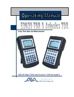
E20/20
Brand: AEA Technology, Inc. Pages: 126

G1000 NAV III
Brand: Garmin Pages: 248
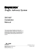
SKY497
Brand: Skywatch Pages: 28

GSU 75 Series
Brand: Garmin Pages: 73

101-200-01
Brand: Skytrac Pages: 50

IN 3A06S
Brand: FPG Pages: 28

EFD1000 Dual EFI
Brand: Aspen Avionics Pages: 163

EFD1000H PFD
Brand: Aspen Avionics Pages: 213


