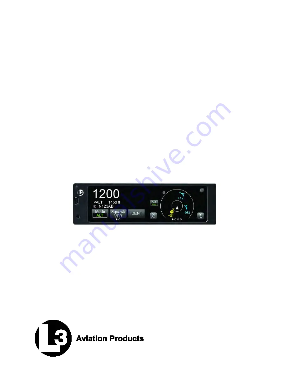
background image


Lynx 

®


NGT-9000 

MultiLink Surveillance System 


Part Number: 9029000-( ) 


Installation Manual


This manual contains installation instructions and 
recommended flightline maintenance information 
for the Lynx  NGT-9000  MultLink  Surveillance 
System, Configuration Module, and Directional 
Antenna. Guidelines for external equipment 
necessary for installation are included. This 
information is supplemented and kept current by 
revisions, service letters and service bulletins. 


0040-17001-01 (Revision A) 

January 15, 2015 


Summary of Contents for NGT-9000 Series

Page 1: ...flightline maintenance information for the Lynx NGT 9000 MultLink Surveillance System Configuration Module and Directional Antenna Guidelines for external equipment necessary for installation are incl...

Page 2: ...cs com This manual is distributed with permission by L 3 Avionics Systems 5353 52 nd Street S E Grand Rapids MI USA 49512 9704 Telephone 800 453 0288 or 616 949 6600 Fax 616 977 6898 Email avionics te...

Page 3: ...ontains instructions for post installation setup post installation and return to service checkout SECTION 4 MAINTENANCE This section contains general flightline maintenance procedures It includes peri...

Page 4: ...ch it is shipped Information in this manual is subject to change without notice and will not be updated after distribution Avionics Systems does provide a listing of all publications and directives wi...

Page 5: ...Lynx NGT 9000s Installation Manual This page intentionally left blank 0040 17001 01 Page iii Revision A January 15 2015...

Page 6: ...ation Module DCM 1 6 1 3 3 System Unlock Code 1 7 1 4 INterfaces 1 7 1 4 1 ADS B Out Fail 1 8 1 4 2 AHRS Input 1 8 1 4 3 Altitude Encoder Input 1 8 1 4 4 Audio Out 1 9 1 4 5 RF Suppression Input outpu...

Page 7: ...3 3 Panel Installation 2 19 2 3 4 Installation 2 21 2 3 5 Antenna Installation Guidelines 2 21 2 3 6 Remove and Replacement Procedures 2 29 Section 3 Installation Checkout 3 1 Introduction 3 1 3 2 Ba...

Page 8: ...8 4 5 4 Configuration Restore 4 28 4 5 5 Service 4 29 4 6 Return to Service 4 30 4 6 1 Lynx NGT 9000s 4 30 4 6 2 Detachable Configuration Module 4 31 4 6 3 Directional Antenna NY156 and NY164 4 32 4 6...

Page 9: ...h Page Appendix B Environmental Qualification Form B 1 Introduction B 1 B 2 NGT 9000 Environmental Qualification Form B 1 B 3 NY156 and NY164 Environmental Qualification Form B 4 APPENDIX C CONFIGURAT...

Page 10: ...a Outline Dimensions 2 26 2 16 Antenna Mounting Holes 2 28 2 17 Directional Antenna Installation 2 28 3 1 Transponder Traffic Screens 3 1 3 2 Maintenance Application Tool Main Page 3 4 3 3 Lynx MAT Ma...

Page 11: ...ce Mode Screens 4 2 4 3 Lynx MAT Update Software 4 15 4 4 Lynx MAT Update Database 4 16 4 5 Lynx MAT Information 4 17 4 6 Lynx MAT Version 4 17 4 7 Lynx MAT Configuration Restore 4 27 4 8 Lynx MAT Ser...

Page 12: ...ctor 1 24 1 14 Coaxial Cable Specifications 1 25 1 15 Directional Antenna SIGMA and DELTA Port Cable Vendors 1 26 1 16 Cable to Connector Reference 1 27 1 17 GPS Antennas 1 28 1 18 L Band Antennas 1 2...

Page 13: ...Beacon System ATM Air Traffic Management AWG American Wire Gauge BIT Built In Test Cal Calibration CCW Counter Clock Wise CDTI Cockpit Display of Traffic Information CFR Code of Federal Regulations C...

Page 14: ...AT Maintenance Application Tool m Meter Max Maximum MSG Message MHz Megahertz mm Millimeter MPC Maintenance Personal Computer MSS MultiLink Surveillance System N A Not Applicable NACp Navigation Accur...

Page 15: ...face application TAF Terminal Area Forecasts TAS Traffic Advisory System TCAS Traffic Alert and Collision Avoidance System TFR Temporary Flight Restrictions TIS B Traffic Information Service Broadcast...

Page 16: ...Lynx NGT 9000s Installation Manual This page intentionally blank Page xiv 0040 17001 01 January 15 2015 Revision A...

Page 17: ...Table 1 1 System Components COMPONENT MODELS H W PART NO S W PART NO MultiLink Surveillance System NGT 9000 1 NGT 9000D 1 9029000 20000 9020010 001 2 Detachable Configuration Module DCM 9230 17003 01...

Page 18: ...ound stations providing immediate surveillance of air to air traffic The 1090ES and UAT ADS B datalink have the following capabilities 1090ES In Receive ADS B ADS R and TIS B 1090ES Out Transmit ADS B...

Page 19: ...B In ADS R transmissions are updated at least every 2 seconds on the surface 5 seconds in the terminal area and 10 seconds in the en route airspace An aircraft on the ground receiving ADS R is provide...

Page 20: ...raffic Advisory solid circle Other Traffic open diamond and colors The effective active mode surveillance range is 35 nmi and track 35 ATCRBS intruders simultaneously with the target bearing relative...

Page 21: ...Lynx NGT 9000s Installation Manual Figure 1 2 Example of Own Aircraft UAT 1090ES and TAS Traffic 0040 17001 01 General Information Page 1 5 Revision A January 15 2015...

Page 22: ...de Input IDENT Traffic graphic and textual Weather graphic and textual TAS Mode model specific 1 3 1 Model Options The Diversity option offers enhanced traffic awareness receiving data via 1090MHz usi...

Page 23: ...ion ARINC 429 Input 4 Receive ADC and AHRS data ARINC 429 Output 1 Transmit to a traffic display Discrete Inputs 17 Receive Gillham Altitude Encoder Audio Mute IDENT Command and In Air On Ground WOW s...

Page 24: ...round open type and is able to sink 250mA 1 4 2 AHRS Input An optional ARINC 429 input is provided to interface to an AHRS heading system in order to provide data for Enhanced Surveillance EHS and ADS...

Page 25: ...available RS 232 to Wifi accessory This interface provides traffic and weather information on a personal electronic device via an approved software application APP 1 4 9 WOW Input The WOW input discre...

Page 26: ...001 The teardrop shaped antenna is sealed against environmental extremes and used by the Unit to receive Active Traffic TAS information 1 4 14 Traffic Display Traffic information is output to a compa...

Page 27: ...hable configuration module 3 GPS Antenna 4 L Band 978 1030 1090 MHz Antenna 5 Altitude Source ARINC 429 RS 232 or Gilham Code A Unit with TAS model NGT 9000 also requires the following 1 Unlock code t...

Page 28: ...with these installation instructions SIZE Case Width 1 48 inches 12 83 cm MAX Height 5 75 inches 7 42 cm MAX Depth 8 99 inches 3 81 cm MAX Bezel Width 6 25 inches 13 44 cm MAX Height 1 8 inches 7 62...

Page 29: ...tart up to power down UAT Receiver Sensitivity Class A1S 95 0dBm for 90 Message Decoding for Long ADS B Messages 96 0dBm for 90 Message Decoding for Short ADS B Messages 93 0dBm for 90 Message Decodin...

Page 30: ...certification information RTCA COMPLIANCE The DCM is tested as part of the NGT 9000 WEIGHT Negligible SIZE Length 6 inches includes wires POWER REQUIREMENTS 3 3 Vdc regulated via J1 connector INTERFA...

Page 31: ...gmented By The Satellite Based Augmentation System TSO C147 TAS System Traffic Advisory System TAS Airborne Equipment TSO C154c UAT IN Universal Access Transceiver UAT Automatic Dependent Surveillance...

Page 32: ...7 Class A Traffic Advisory System TAS Airborne Equipment DO 197A Traffic Advisory System C154c Class A1S Receive Only Universal Access Transceiver UAT Automatic Dependent Surveillance Broadcast ADS B...

Page 33: ...O C154c 4 a TSO C157a 4 a TSO C166b 4 a TSO C195a 4 a Per the guidance in FAA Order 8150 1c the appliances are marked with the primary TSO along with a reference to the Installation Manual for the oth...

Page 34: ...CRBS traffic from the display when the heading input is not available would significantly reduce the value of the CDTI s support in the pilot s see and avoid responsibilities ACSS proposes the DO 317A...

Page 35: ...cant reduction in safety margins or functional capabilities ADS B Output Major AC 20 165A Appendix 1 cc TSO C166b 3 b TSO C154c 3 b Incorrect position or velocity data reported to ground surveillance...

Page 36: ...database versions can be viewed using the MPC via the Maintenance Application Tool A list of current software revisions is identified below Table 1 10 Software Revisions DESCRIPTION REVISION PART NUM...

Page 37: ...et for actual attenuation insertion loss for the cable being used Directional Antenna Required only for models with TAS The Directional Antenna NY156 or NY164 requires three cable assemblies sum Sigma...

Page 38: ...s For Grounding Solder Sleeves Cable tie Tie wrap Ground Braid RAY 101 20 0 AA59569R36TXXXX or equivalent Coaxial connectors Fusion tape Installation Kits Installation Kits for the unit and Directiona...

Page 39: ...and antenna Directional antenna install kits and any display A list of compatible components is found in paragraph 1 11 Test Equipment Air Data Test Set Required to test altitude inputs Maintenance Co...

Page 40: ...0 4 40 x 0 438 NAS514 P 440 7 4 Grounding Clip Copper Spring With Ground Finger Stock 9001963 001 1 Wire Clamp Pad 9000 17132 01 2 Table 1 13 Installation Kit P N 9060 17000 02 for Right Angle RF Conn...

Page 41: ...RG304 RG 304 9 2 N A M17 127 RG393 RG 393 15 2 3C142B N A N A 9 2 311601 N A N A 7 5 311501 N A N A 5 8 311201 N A N A 3 8 310801 N A N A 1 RG type coaxial cable insertion loss can vary significantly...

Page 42: ...1 4 5 Frequency 1030 MHz Loss 1 5 dB at 1030 MHz includes all cables and connectors VSWR 1 5 1 at 1030 MHz Connectors have 0 2db loss each Manufacturer Electronic Cable Specialists Part Number Attenua...

Page 43: ...5 100 TMS165 1 TMR165 1 BMS165 1 BMR165 1 TFLX205 100 TMS205 1 TMR205 1 BMS205 1 BMR205 1 TFLX225 100 TMS225 1 TMR225 1 BMS225 1 BMR225 1 TFLX295 100 TMS295 1 TMR295 1 BMS295 1 BMR295 1 TFLX480 100 TM...

Page 44: ...can be found in the installation section of this manual All listed GPS antennas have TNC connector Table 1 17 GPS Antennas MANUFACTURER PART NUMBER AeroAntenna AT575 326W TNCF 000 RG 30 NM AeroAntenn...

Page 45: ...nformation relative to the radius of the area where the antenna is to be mounted Table 1 19 Directional Antenna Model Options and Specifications PART NUMBER 805 10003 001 NY156 White Paint Used for In...

Page 46: ...004 800 10066 003 Special Adapter Plate 32 Inch 81 3 cm Radius 1 817 10009 005 800 10066 005 Special Adapter Plate 47 Inch 119 4 cm Radius 1 817 10009 006 No Adapter Plate 100 10022 001 101 10027 001...

Page 47: ...1 2 13 Garmin MX 20 Standard traffic only 1 Version 5 7 Notes 1 For Installations using the MX 20 or GMX 200 Traffic may be displayed using the ARINC 429 interface GMX 200 requires optional 429 card...

Page 48: ...ccount will be converted to a RBA account The expiration date is located on the back of the RSA token First time users of RBA 1 Go to https www l 3avionics com customer support technical publications...

Page 49: ...public or shared computer question Click the Continue button 6 After successful authentication the license agreement screen is shown Click the I Agree button to be taken to the home page Users with R...

Page 50: ...ware and has restricted access beyond what is required for the publication Contact the Manuals Administrator at avionics techpubs l 3com com for access The software notices for the unit are listed in...

Page 51: ...ction for loading and validation instructions Table 1 27 System Software CD Part Numbers and Contents PART NUMBER RELEASE CONTENTS 9230 17000 0100 1 0 1 Software Executable Object Code Graphics Data 9...

Page 52: ...g The MSS Appliance and MPC have power applied The driver has been downloaded from the internet or is available via CD The MSS Appliance is connected to the MPC via USB cable 1 12 3 1 Windows XP Insta...

Page 53: ...S Driver file and press the Open button 7 Press the OK button A screen with Lynx MSS as the Model is shown See Below 8 Press the Next button The driver installation process begins See Below 9 When the...

Page 54: ...tallation fails a dialog window is shown Close out of that window 3 Open the Devices and Printers from the Start menu An unspecified device with the label NGT should be available See below 4 Double cl...

Page 55: ...the Browse my computer for driver software 10 Browse to the Windows 7 USB Driver folder and select Open See below 11 Select Next The driver installation process begins 12 When the installation complet...

Page 56: ...equirements specified in this manual 4 The use of a frequency diplexer is not supported and as such the L Band antenna cannot be diplexed with another L band antenna 5 It is the installer s responsibi...

Page 57: ...ify a claim retain the original shipping container and all packing materials Every effort should be made to retain the original shipping containers for storage If the original containers are not avail...

Page 58: ...060 17000 01 o Rack Assembly with Right Angle Coax Connector P N 9060 17000 02 All antenna cables should be clearly marked to prevent inadvertent installation into the wrong connector position Tighten...

Page 59: ...een control is within easy reach of the pilot and cannot be obstructed from continuous view i e behind a control yoke 5 A Mounting Rack is required to install the panel mount NGT 9000 Two installation...

Page 60: ...Lynx NGT 9000s Installation Manual Figure 2 1 Outline Dimensions for Panel Mount NGT 9000 Page 2 4 Installation 0040 17001 01 January 15 2015 Revision A...

Page 61: ...Lynx NGT 9000s Installation Manual Figure 2 2 Outline Dimensions for Mounting Rack 0040 17001 01 Installation Page 2 5 Revision A January 15 2015...

Page 62: ...tallation kits paragraph 1 7 All wires should be 22 AWG or 24 AWG as noted in the interconnect diagram Use M22759 or equivalent wire and Tefzel Wire M27500 or equivalent for twisted shielded wired for...

Page 63: ...using the GMX 200 connect the Lynx NGT 9000s TX pins 52 53 only 2 3 2 1 Shielded Cable Preparation Use these instructions to prepare the Shielded Tefzel Wire MIL27500 or equivalent for connection to...

Page 64: ...lay flat and smooth a Position the stripped portion of ground lead s against the stripped portion of the shield braid b Slip the selected shield terminator over the cable and ground lead assembly Rot...

Page 65: ...mbly toward the heat source to minimize unwanted exposure of the jacket to the heat e Heat until the solder preform melts flows and wets the shield and ground lead f Some terminators contain a thermal...

Page 66: ...Lynx NGT 9000s Installation Manual Figure 2 3 Interconnect Wiring Diagram Sheet 1 of 3 Page 2 10 Installation 0040 17001 01 January 15 2015 Revision A...

Page 67: ...Lynx NGT 9000s Installation Manual Figure 2 3 Interconnect Wiring Diagram Sheet 2 of 3 0040 17001 01 Installation Page 2 11 Revision A January 15 2015...

Page 68: ...Lynx NGT 9000s Installation Manual Figure 2 3 Interconnect Wiring Diagram Sheet 3 of 3 Page 2 12 Installation 0040 17001 01 January 15 2015 Revision A...

Page 69: ...Lynx NGT 9000s Installation Manual Figure 2 4 Mating Connector P1 and Pin Assignments 0040 17001 01 Installation Page 2 13 Revision A January 15 2015...

Page 70: ...em 9 using 6 Screws P N 2000 10087 01 item 22 Refer to Figure 2 12 for the installation location of the other side of the cable ground strap 4 Insert Wires to P1 Mating Connector 5 Secure Wires to Wir...

Page 71: ...Lynx NGT 9000s Installation Manual Figure 2 6 Outline Dimensions for the Data Configuration Module 9230 17003 01 0040 17001 01 Installation Page 2 15 Revision A January 15 2015...

Page 72: ...ce 4 6 inches 10 2 to 15 2 cm of heat shrink tubing over each antenna connector and cable to add strain relief and alleviate stress caused by aircraft vibration When routing antenna cables observe the...

Page 73: ...the sum antenna cable with a TNC connector at each end Affix a blue marking band on each connector At the NGT 9000 the sum port A4 is identified with blue marking Bit Probe Port The Bit Probe port A1...

Page 74: ...act Assembly Refer to Figure 2 10 for the following instructions 1 Twist center conductor tight and bend wire end slight upwards 2 Slide Contact over inner insulator The copper shield must be over the...

Page 75: ...or 1 Refer to Figure 2 11 2 Secure Backshell P N 9000 17105 01 item 17 to Connector P N 9080 17007 01 item 15 using 4 screws P N 2000 10085 01 item 7 3 Insert Cables into the appropriate slots of Conn...

Page 76: ...m 1 using 4 Screws P N NAS514 P 440 5 item 4 5 Place the assembled Panel Rack P N 9010 17022 01 item 1 in the location selected in paragraph 2 3 1 6 Secure Panel Rack using 6 Screws P N MS35206 230 it...

Page 77: ...for the GPS and L band antennas is not provided by the instructions provided in this manual Installation approval for the GPS and L band antennas is not provided by the instructions provided in this...

Page 78: ...ts of airframe shadowing during typical maneuvers Typically mounting farther away from the tail section reduces signal blockage seen by the antenna 2 Mount the antenna as close to level as possible wi...

Page 79: ...ify an existing antenna location is acceptable for use 2 3 5 2 1 L band Antenna Location The L band antenna installation should be installed in accordance with AC 43 12 2A Chapter 3 The following guid...

Page 80: ...ance with the system interconnect diagram Figure 2 3 All antenna cables should be clearly marked as both connections use TNC connectors Acceptable coaxial cable attenuation including connectors shall...

Page 81: ...r the directional antenna The antenna should be mounted on the aircraft with at least 20 dB isolation about 30 inches 76 2 cm from other L band frequency antennas and 24 inches 61 0 cm from other ante...

Page 82: ...Lynx NGT 9000s Installation Manual Figure 2 15 NY156 NY164 Directional Antenna Outline Dimensions Page 2 26 Installation 0040 17001 01 January 15 2015 Revision A...

Page 83: ...doubler plate not supplied is required to reinforce the aircraft skin 2 Connect each of the three antenna cables Check to ensure that each cable is connected to the correct antenna connector Each con...

Page 84: ...Lynx NGT 9000s Installation Manual Figure 2 16 Antenna Mounting Holes Figure 2 17 Directional Antenna Installation Page 2 28 Installation 0040 17001 01 January 15 2015 Revision A...

Page 85: ...placement Procedures If the unit or one of its system components requires removal after initial installation replace it using the instructions given in the maintenance section of this manual 0040 1700...

Page 86: ...Lynx NGT 9000s Installation Manual This page intentionally blank Page 2 30 Installation 0040 17001 01 January 15 2015 Revision A...

Page 87: ...rmation It should be filled out prior to performing this procedure NOTE These procedures assume that the mounting wiring power and antenna requirements have been checked out according to the instructi...

Page 88: ...screen also shows the information screens GPS brightness control etc A version screen is shown at start up It identifies version information for the units Application Software Flight Sw Firmware Plat...

Page 89: ...in either Normal Operation or in Ground Test modes When Maint status is shown the unit is in Maintenance mode with or without Wifi The Restart function of the Lynx MAT may be used to restart into Nor...

Page 90: ...n bar See Figure 3 3 If Not Connected red indicator is shown then check the USB cable for proper connection If a Response timeout for write request message is seen on the status bar then the unit is n...

Page 91: ...the MPC and the unit via the WiFi connection The WiFi connection is optional NOTE The Configure WiFi Accessory procedure described in 3 5 must be completed before the unit can establish a WiFi connect...

Page 92: ...ndow is shown on the right screen See Figure 3 5 Figure 3 5 Activate Maintenance Mode Window 3 Tap the Yes button to restart the unit in Maintenance Mode Note Tapping the No screen button or 10 second...

Page 93: ...ory Type 6 Enter the SSID 4 x only if the entry field is not grayed out and accessible Otherwise the SSID is already loaded 7 Click Configure to begin A message is shown to indicate configuration comp...

Page 94: ...are communicating From the Lynx MAT panel select ConnectZNGT9000ZUSB This is required each time the unit power is cycled 1 From the Lynx MAT select InfoZVersions See Figure 3 8 2 Use the versions scre...

Page 95: ...maintenance section of this manual Unlock codes are required to enable TAS and Diversity configuration selections The unlock codes are typically shipped with the unit If the unlock codes are not inclu...

Page 96: ...lect Disabled or Enabled This selection only works for models of the Lynx NGT 9000 with TAS functionality When enabled the aural alert Traffic Traffic is heard over the audio system when traffic advis...

Page 97: ...ype information If no emitter category fits the installation seek guidance from the FAA Light Light ICAO 15 500 lbs This includes very light aircraft light sport aircraft that do not meet the requirem...

Page 98: ...etween the longitudinal center line of the aircraft and the GPS See AC 20 165A Appendix 1 GPS Antenna Offset Longitudinal feet Length offset See GPS Antenna Offset Lateral feet above GPS Antenna Offse...

Page 99: ...he following ARINC 429 RS 232 Altitude Encoder Port RS 232 Control Panel Port Gilham Interface b Protocol These options are available only when the selected source is RS 232 Altitude Encoder Port c RS...

Page 100: ...e unit to an approved traffic display 2 RS 422 Set up the RS 422 interface as follows a Baud Rate Select a baud rate appropriate to the equipment connected via the RS 422 bus b ADS B Output This optio...

Page 101: ...the values are reset to defaults Discrete Override Speed Applicable only when On Ground Discrete installed and not a Rotorcraft When applicable the valid range is 30 to 100 typically 130 of Vs1 and m...

Page 102: ...d status bar indicates Save of DCM succeeded If the DCM data is not loaded after the Save button is pressed a message is shown on the screen to indicate this Instructions are given on how to attempt t...

Page 103: ...o listen to the audio level selected 4 Repeat step 2 and 3 until audio volume is set to the level desired The audio test may need evaluation with both low and high cockpit noise present Figure 3 13 Ly...

Page 104: ...factory configuration and calibration angle is written into the configuration module for subsequent use If calibration fails then the message Calibration Failed is shown on the traffic application sc...

Page 105: ...the current state of the discrete e g True for the squat on ground means that the aircraft is on ground A false would mean that the aircraft was not on the ground at least according to the discrete No...

Page 106: ...received and signal strength is within 30 to 50 db Note the Navigation State always shows RAIM even though the device is actually in WAAS mode 4 If data is not being received do the following The GPS...

Page 107: ...sages A zero is a valid number if the unit is not in range of a signal If data is not being received do the following The signal may be blocked move the aircraft to an open environment or input a sign...

Page 108: ...ly ground mutes the signal from the Audio Mute Out to check the Audio Mute is working correctly Click Not simulating to remove simulated data Click either simulated ground or open per the installation...

Page 109: ...d GPS is initializing acquiring signal It is normal for the TIS B Out Of Coverage lamp to be ON during checkout if there is not a ground station or signal within range 3 10 1 Functional Checks Use the...

Page 110: ...right side of the display The option to restart the unit or to continue start up in a degraded mode is shown on the right side of the display Press the Restart or Continue button to proceed If System...

Page 111: ...Restart button and perform the System Test again If the failures continue press the Continue button to proceed If Degraded is shown for any of the system functions then the message Service Unit Soon...

Page 112: ...in view 5 Turn ON other avionics and verify that the signal bars are showing at least 40 50 in the GPS Receiver Information Packet for the satellites do not degrade significantly and position remains...

Page 113: ...shed when testing with an IFR 6000 It will only extinguish when within coverage of a ground station 3 10 1 5 Discrete Switch Checks Verify the following external switches are functioning properly if i...

Page 114: ...unit to In Air status allowing Mode C altitude output and additional ADS B output messages sent at a higher rate o In Air status also allows Mode A i e squawk code While on ground both Mode A and C r...

Page 115: ...ponder Output Check Verify that the Transponder test performed by the test set is successful and that the test set is receiving the correct transponder information i e Mode S Identifier Flight ID etc...

Page 116: ...y 978 MHz TIS B In traffic information display on the unit with that being transmitted by the test set a From the ADS B GICB UAT screen on the IFR 6000 select UAT then UAT GEN then TIS B Ensure target...

Page 117: ...rrect Traffic Advisories have occurred on the unit Intruding flight patterns are programmed from the IFR 6000 screen 2 Verify that Traffic information displayed on the unit with that being transmitted...

Page 118: ...ng frequencies for VHF radios with 8 33 kHz channel spacing 121 185 MHz 121 190 MHz 130 285 MHz 131 290 MHz 2 Navigation a VOR ILS Verify the operation of each VHF Nav receiver in both VOR and ILS mod...

Page 119: ...rting equipment 2 Verify that system status has passed 3 Verify that there are no new system messages indicated by a blinking MSG button 4 Verify that the Transponder Application left screen and the T...

Page 120: ...Lynx NGT 9000 Installation Manual This page intentionally blank Page 3 34 Installation Checkout 0040 17001 01 January 15 2015 Revision A...

Page 121: ...wiring shield terminations for proper grounding routing and attachment clamping Visually inspect the unit mounting to the aircraft verify visually that the screw heads are in full contact with the mou...

Page 122: ...n See Figure 4 1 Figure 4 1 Activate Maintenance Mode Window 4 Tap the Yes button to restart the unit in Maintenance Mode Note Tapping the No screen button or 10 seconds of inactivity starts normal op...

Page 123: ...4 5 3 2 list of fault log messages and Table 4 3 for instructions on viewing fault logs and using the service functions of the Lynx MAT The information provided here should be in conjunction with the...

Page 124: ...ule Configuration Validity Mutual Suppression Bus Self Test Over Temperature Monitor in air Power Fail Monitor Although no immediate loss of function is occurring an undesired condition is taking plac...

Page 125: ...System Status Messages 4 Check the Lynx MAT fault log 5 Contact L 3 Field Service before removal of unit Display indicator TAS ONLY Models with TAS only showing on traffic screen MSG button on screen...

Page 126: ...transmitting TIS B data 2 The target or ground station needs to be within line of site range 3 Contact L 3 Field Service before removal of unit Other aircraft are not shown on the traffic screen Ownsh...

Page 127: ...on is not active 3 The TAS requires other aircraft to be equipped with equipped with an active ATCRABS transponder Display indicator ON GND showing on transponder screen Transponder Transponder is ope...

Page 128: ...er Information MPC Service GPS for correct signal strength C No of the GPS satellites This has a range from 30 dB to 50 dB If this is not the case then check if the antenna cable loss is more than 10...

Page 129: ...never a failure or degraded window message is shown It may be used to begin normal operation with degraded performance The unit continues to operate non fatal failures detected during the System Test...

Page 130: ...ment for errors 3 If the problem continues replacement of the unit or GPS antenna may be required Contact L 3 Field Service before removal ADS B In Degraded The message is seen if any of the following...

Page 131: ...screte 1 Try clearing the failure performing a warm startup by tapping the Restart button 2 Check the audio mute wiring or interface for possible errors 3 Contact L 3 Field Service if problem continue...

Page 132: ...s replacement of the GPS antenna or unit may be required Contact L 3 Field Service before removal GPS External Fail The message is seen if the follow test fails GPS Antenna Cable 1 Try clearing the fa...

Page 133: ...pping the Restart button to perform a warm startup 2 The unit configuration data may be corrupted or missing Using the instructions provided in this manual to load the configuration data 3 Replacement...

Page 134: ...r RS 232 Input Altimeter ARINC 429 Input 1 Try clearing the failure performing a warm startup by tapping the Restart button 2 Check that the equipment listed above is operational 3 If the problem cont...

Page 135: ...nal instructions on using the MPC are given in the Installation Checkout section 4 5 1 Load Software This procedure is used to update the system software used by the unit The MPC must be connected via...

Page 136: ...correctly Refer to the fault isolation section if errors are detected 4 5 2 Load Databases This procedure is used to update the databases used by the Lynx NGT 9000s Updates to the databases are not ma...

Page 137: ...s data event log and factory log can be saved to a file for later viewing Figure 4 5 Lynx MAT Information 4 5 3 1 Versions The Versions page shows the current software and database versions on the uni...

Page 138: ...ult persists Contact L 3 Field Service before removal 0x00000003 Kernel Fault Thread Term Reboot the unit and check if the fault persists Contact L 3 Field Service before removal 0x00000004 Kernel Fau...

Page 139: ...ore removal 0x00000048 Fault ID for the memory test failure Reboot the unit and check if the fault persists Contact L 3 Field Service before removal 0x00000049 Fault ID for the DSP Clock test failure...

Page 140: ...act L 3 Field Service before removal 0x00001008 Over Temp in Air No failures of the box only log the fault Log the fault and allow the unit to cool down If the fault continues to be seen contact L 3 F...

Page 141: ...Field Service before removal 0x00001017 Factory Data NVM CRC Failure Failure causes a reset Reboot the unit and check if the fault persists Contact L 3 Field Service before removal 0x00001018 Factory...

Page 142: ...fig Data RAM CRC Failure Log the fault 0x00001817 Clear Factory Data NVM CRC Failure Log the fault 0x00001818 Clear Factory Data Compatibility Failure Log the fault 0x00001819 Clear Config Data NVM CR...

Page 143: ...ssion Failure Transponder Internal failure ADS B Out Internal failure Reboot the unit and check if the fault persists Contact L 3 Field Service before removal 0x00003003 Squitter rate failure ADS B Ou...

Page 144: ...e unit and check if the fault persists Contact L 3 Field Service before removal 0x0000300E XPDR 1090 XMIT Top Power Failure Transponder Internal failure ADS B Internal failure Reboot the unit and chec...

Page 145: ...Service before removal 0x00005801 Clear UAT Sensor Failure Log the fault 0x00006003 Gillham C Bit Error ADS B In External failure TAS External failure Transponder External failure Check wiring Reboot...

Page 146: ...Service before removal 0x00006803 Clear Gillham C Bit Error Log the fault 0x00006804 Clear RS232 Altitude Input Fail Log the fault 0x00006805 Clear ARINC 429 Altitude Input Fail Log the fault 0x000068...

Page 147: ...file is loaded into the Lynx MAT click on any of the Apply buttons to save all the configuration options see Note below Note A dialog window is shown asking if changes should be saved immediately See...

Page 148: ...Lynx MAT select ServiceZRestart Unit ModeZ Operational Mode 5 Data recording begins Recording continues until the unit is restarted again 6 From the Lynx MAT select ServiceZRestart Unit ModeZ Mainten...

Page 149: ...a Use 3 32 Allen Hex Socket Screw Driver to rotate the Panel Retainer CCW to avoid interference with the bottom edge of the panel b Insert the unit in panel allowing the alignment guides to settle the...

Page 150: ...b Slide overbraid back into position and use a new tie wraps to secure overbraid c Secure P1 mating connector to rear plate using nut plate and 2 screws d Secure cable ground strap to rear plate usin...

Page 151: ...uirements of SAE AMS S 8802 such as Flamemaster CS3204 class B For non pressurized aircraft use a non corrosive sealant that meets the physical requirements of MIL A 46146 such as General Electric RTV...

Page 152: ...htly crystals in bag form cannot be used The use of loose crystals may cause unnecessary damage resulting in a cleaning problem a Ensure that conductive covers caps are installed on the exposed termin...

Page 153: ...positive voltage on the output to provide the suppression to other L band equipment on the airplane The suppression pulse output is DC coupled and drives positive pulses not less than 18 Vdc or greate...

Page 154: ...t The RS 232 WiFi interface is optional An optional equipment interface wiring diagram is shown in Figure A 1 When configured the NGT 9000 outputs the following information to a WiFi connection FIS B...

Page 155: ...200 bps Data bits 8 Parity none 4 When the UPS AT Loran 618 protocol option is used the following characteristics are set Requires Altitude Encoder and Control Panel interface Baud rate is set to 1200...

Page 156: ...on Bus 1 Label 203 Pressure Altitude Uncorrected BNR Label 204 Baro Corrected Altitude BNR Label 205 Mach BNR Label 206 Computed Airspeed BNR Label 210 True Airspeed BNR Label 212 Altitude Rate BNR L...

Page 157: ...C Label 015 Altitude Select Limits DSC Label 016 Mode S Control Panel Data DSC Label 163 Application Availability DSC Label 270 Vertical Resolution Advisories DSC Label 274 Selected Sensitivity Level...

Page 158: ...whether ownship is in air or on ground The discrete is called Weight On Wheels WOW which can be connected to either a squat switch airspeed monitor or a collective switch The discrete can be set in t...

Page 159: ...ght ID Aircraft Length and Width Code Aircraft Maximum Airspeed Normal Traffic Color 5 AHRS and Altitude Configuration Options AHRS Source AHRS ARINC 429 Bus Speed Altitude Source RS 232 Altitude Prot...

Page 160: ...15 GILHAM ALTITUDE ENCODER D4 I 54 SPARE S 16 GROUND C 55 SPARE S 17 I2C DATA LINE I 56 SPARE S 18 I2C CLOCK LINE I 57 SPARE S 19 3 3V OUTPUT O 58 SPARE S 20 3 3V RETURN C 59 SPARE S 21 RESERVED R 60...

Page 161: ...al Name Ground Signal Function 14 28 V Power Return 1 Electrical Characteristics Connection Aircraft 14 or 28V Return BUS 22 AWG wire Comments PIN 4 Signal Name Ground Signal Function 14 28 V Power Re...

Page 162: ...10 k per line Max Capacitance 20 pF per line Connection See paragraph A 2 4 24 AWG wire Comments PIN 8 Signal Name ALT_IN_B1 Signal Function Gilham Altitude Encoder Electrical Characteristics 30 V in...

Page 163: ...10 k per line Max Capacitance 20 pF per line Connection See paragraph A 2 4 24 AWG wire Comments PIN 12 Signal Name ALT_IN_C2 Signal Function Gilham Altitude Encoder Electrical Characteristics 30 V i...

Page 164: ...A sourced per line Frequency 20 Hz Source Z 10 k per line Max Capacitance 20 pF per line Connection See paragraph A 2 4 24 AWG wire Comments PIN 16 Signal Name GROUND Signal Function Signal Ground Ele...

Page 165: ...round for voltages applied to the output of 0 0 to 36 0Vdc Connection No Connection Comments See paragraph A 2 10 PIN 22 Signal Name DISC_OUT2 Discrete Output No 2 Signal Function Reserved TAWS Warnin...

Page 166: ...en State has an impedance of 100K ohms to ground for voltages applied to the output of 0 0 to 36 0Vdc Connection No Connection Comments See paragraph A 2 10 PIN 26 Signal Name DISC_OUT6 Discrete Outpu...

Page 167: ...5Vdc Open State 18Vdc Connection On Off Switch 24 AWG wire Comments See paragraph A 2 9 PIN 30 Signal Name DISC_IN4 Discrete Input No 4 Signal Function Reserved TSAA Inhibit Electrical Characteristics...

Page 168: ...Function Spare pin Electrical Characteristics Connection No Connection Comments PIN 35 Signal Name Spare Signal Function Spare pin Electrical Characteristics Connection No Connection Comments PIN 36 S...

Page 169: ...teristics Configuration Option Low Speed ARINC 429 12 0 to 14 5 kbps High Speed ARINC 429 100 kbps Connection 24 AWG twisted shielded pair wire Comments See paragraph A 2 7 PIN 41 Signal Name RX1_429B...

Page 170: ...e paragraph A 2 7 PIN 45 Signal Name RX3_429B ARINC 429_3_IN B Signal Function Reserved Electrical Characteristics Configuration Option Low Speed ARINC 429 12 0 to 14 5 kbps High Speed ARINC 429 100 k...

Page 171: ...configuration option 38400 57600 or 115200 Depending on the equipment manufacturer Connection Optional 24 AWG twisted shielded pair wire Comments See paragraph A 2 6 PIN 51 Signal Name RS422_RX2B Sign...

Page 172: ...sted shielded pair wire Comments See paragraph A 2 6 PIN 54 Signal Name Spare Signal Function Spare pin Electrical Characteristics Connection No Connection Comments PIN 55 Signal Name Spare Signal Fun...

Page 173: ...n Optional 24 AWG twisted shielded pair wire Comments See paragraph A 2 5 2 PIN 61 Signal Name RS232_RX1 Signal Function RS 232 Control Panel Interface Electrical Characteristics Data bits 8 Parity no...

Page 174: ...istics Data bits 8 Parity none Stop bit 1 Start bit 1 Data format is ASCII Flow control is none Baud Rate 115200 bps Connection Optional 24 AWG twisted shielded pair wire Comments See paragraph A 2 5...

Page 175: ...Signal Name Spare Signal Function Spare pin Electrical Characteristics Connection No Connection Comments PIN 71 Signal Name Spare Signal Function Spare pin Electrical Characteristics Connection No Con...

Page 176: ...l Name RESEARVED Signal Function TCAS Pretrigger test output Electrical Characteristics Connection No Connection Comments FACTORY ONLY PIN 77 Signal Name RESEARVED Signal Function XPDR Pretrigger test...

Page 177: ...nfiguration Module PART NUMBERS 9230 17003 01 MANUFACTURER Aviation Communication and Surveillance Systems ADDRESS ACSS 19810 N 7th Avenue Phoenix AZ 85027 4741 DESCRIPTION SECT NO CAT DESCRIPTION Tem...

Page 178: ...sive Atmosphere 9 X Not Applicable Not Tested Waterproofness 10 X Not Applicable Not Tested Fluids Susceptibility 11 X Not Applicable Not Tested Sand and Dust 12 X Not Applicable Not Tested Fungus Res...

Page 179: ...veform 3 600 VT 120IL Waveform 3 600 VT 120IL J3 Cable Bundle Multiple Stroke Waveform 1 First Stroke 300 VL 300 IT Sub Strokes 150 VL 150IT Waveform 3 First Stroke 600 VL 120 IL Sub Strokes 300 VL 60...

Page 180: ...ibration 8 0 Equipment tested to Category C L M and Y Explosion 9 0 Category X No test performed Waterproofness 10 0 Equipment tested to Category S Fluids Susceptibility 11 0 Equipment tested to Categ...

Page 181: ...___________________ Mode S Identifier Octal ____________________ Transponder Diversity d Disabled d Enabled TAS Enable d Disabled d Enabled TAS Extended Callout Enable d Disabled d Enabled TAS Directi...

Page 182: ...ilable ARINC 429 Output 1 d None d CDTI RS 422 Baud Rate d 38400 d 57600 d 115200 RS 422 ADS B Output d Disabled d Enabled RS 422 Weather Output d Disabled d Enabled CDTI Output d TIF d DTIF d Both Co...

Reviews: