
5-2-55, Minamitsumori, Nishinari-ku, Osaka 557-0063 JAPAN
Phone: +81(6)6659-8201 Fax: +81(6)6659-8510 E-mail: info@m-system.co.jp
EM-9441-A Rev.9 P. 1 / 9
INSTRUCTION MANUAL
BARGRAPH INDICATING ALARM
(with 4-digit digital meter; with isolated DC output)
MODEL
48NDVA
BEFORE USE ....
Thank you for choosing M-System. Before use, please check
contents of the package you received as outlined below.
If you have any problems or questions with the product,
please contact M-System’s Sales Office or representatives.
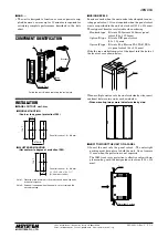
■
PACKAGE INCLUDES:
Bargraph indicator (incl. scale plate) .................................(1)
Mounting bracket ................................................................(2)
Bezel*
1
..................................................................................(2)
Watertight packing .............................................................(1)
*1. The size of included bezel differs depending on option code.
■
MODEL NO.
Confirm Model No. marking on the product to be exactly
what you ordered.
■
INSTRUCTION MANUAL
This manual describes necessary points of caution when
you use this product, including installation, connection and
basic maintenance procedures.
For detailed explanations to operate and program the
module, please refer to Model 48NDVA Operating Manual
(EM-9441-B), downloadable at M-System’s web site: http://
www.m-system.co.jp.
POINTS OF CAUTION
■
CONFORMITY WITH EU DIRECTIVES
• This equipment is suitable for Pollution Degree 2, Meas-
urement category II (alarm output, transient voltage
2500V) and Installation Category II (transient voltage
2500V). Reinforced insulation (signal input to alarm out-
put to power input and DC output to power input: 300V)
is maintained. Prior to installation, check that the insu-
lation class of this unit satisfies the system requirements.
• The equipment must be mounted on a panel surface.
Once mounted on a panel, take appropriate precautions
to prevent operators to be exposed to the terminal block.
• Altitude up to 2000 meters.
• Insert a noise filter for the power source connected to the
unit. TDK-Lambda Noise Filter Model RSAN-2006 or
equivalent is recommended.
• The equipment must be installed such that appropriate
clearance and creepage distances are maintained to con-
form to CE requirements. Failure to observe these re-
quirements may invalidate the CE conformance.
• The actual installation environments such as panel con-
figurations, connected devices, connected wires, may af-
fect the protection level of this unit when it is integrated
in a panel system. The user may have to review the CE
requirements in regard to the whole system and employ
additional protective measures to ensure the CE conform-
ity.
• In order to enable the operator to turn off the power in-
put immediately, install a switch or a circuit breaker ac-
cording to the relevant requirements in IEC 60947-2 and
properly indicate it.
■
POWER INPUT RATING & OPERATIONAL RANGE
• Locate the power input rating marked on the product and
confirm its operational range as indicated below:
100 – 240V and 85 – 264V AC rating: 85 – 264V,
50/60 Hz, approx. 5.5 – 8VA
24V DC rating: 24V ±15%, approx. 3.5W
■
GENERAL PRECAUTIONS
• Before you remove the unit or mount it, turn off the power
supply and input signal for safety.
• Be sure to put the terminal cover on while the power is
supplied.
■
ENVIRONMENT
• Indoor use.
• If the unit’s environmental protection is compromised
(e.g. when multiple units are to be mounted side by side)
when heavy dust or metal particles are present in the air,
install them inside an enclosure with a proper ventila-
tion.
• Do not install the unit where it is subjected to continuous
vibration. Do not subject the unit to physical impact.
• Environmental temperature must be within -5 to +55°C
(23 to 131°F) with relative humidity within 30 to 90% RH
in order to ensure adequate life span and operation.
■
REQUIREMENTS TO ENSURE IP65
• Observe the designated panel cutout size (31.5 × 138 mm).
• Single mounting only. IP65 is not ensured when the units
are clustered side by side.
• The watertight packing included in the product package
must be placed behind the front cover.
• The mounting bracket must be fastened tightly until they
hit the panel.
• Confirm visually that the packing is not contorted or ex-
cessively run off the edge after installation.
■
WIRING
• Do not install cables close to noise sources (relay drive
cable, high frequency line, etc.).
• Do not bind these cables together with those in which
noises are present. Do not install them in the same duct.
■
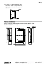
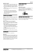
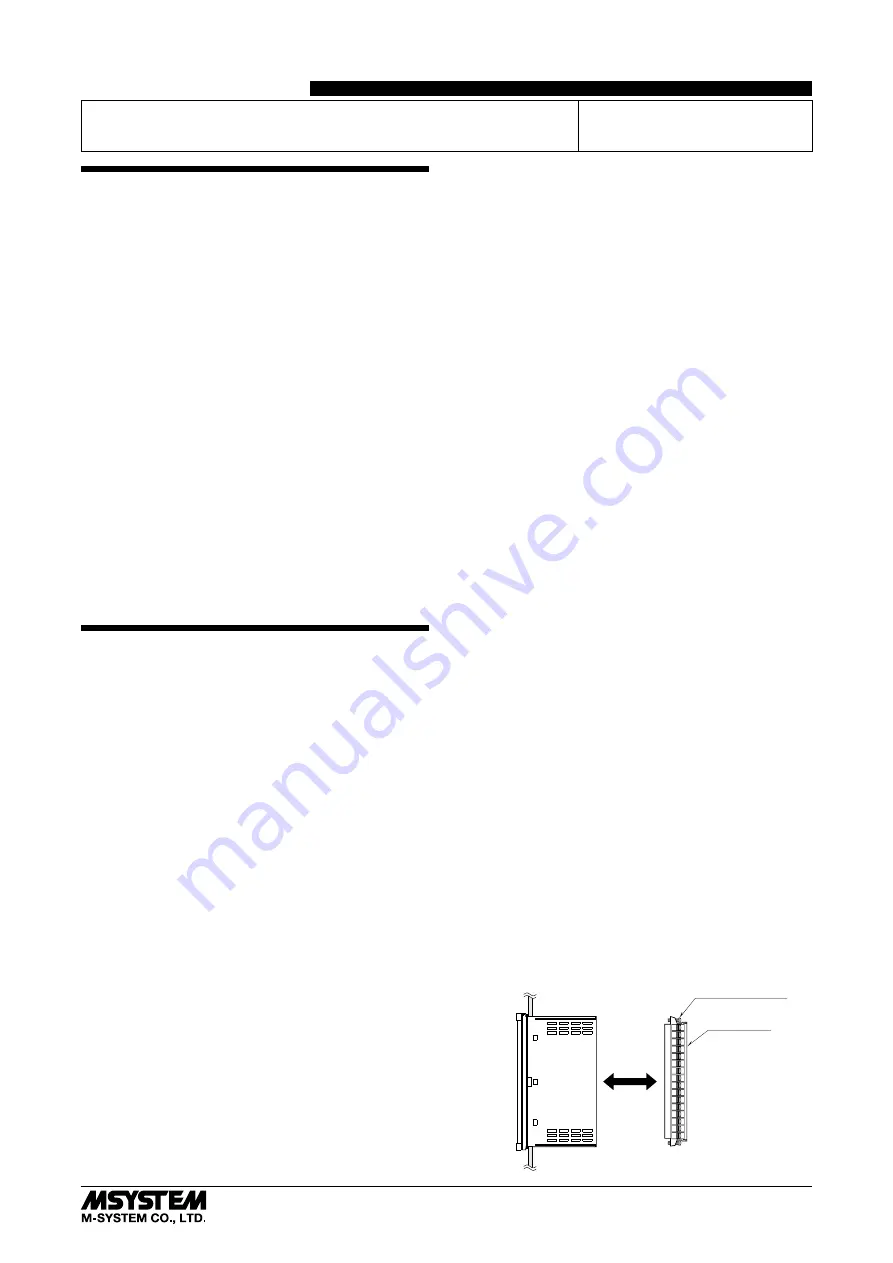
TERMINAL BLOCK
• The terminal block is separable in two pieces. Loosen two
screws on top and bottom of the terminal block to sepa-
rate.
• Be sure to turn off the power supply, input signal and
power supply to the output relays before separating the
terminal block.
Terminal Block
Separable
Terminal Block Screw
(top & bottom)


