
BEFORE USE ....
Thank you for choosing M-System. Before use, please check
contents of the package you received as outlined below.
If you have any problems or questions with the product,
please contact M-System’s Sales Office or representatives.
■
PACKAGE INCLUDES:
DC alarm (body + base input resistor) ................(1)
Input resistor is provided only with current input type.
■
MODEL NO.
Confirm Model No. marking on the product to be exactly
what you ordered.
■
INSTRUCTION MANUAL
This manual describes necessary points of caution when
you use this product, including installation, connection and
basic maintenance procedures.
POINTS OF CAUTION
■
CONFORMITY WITH EU DIRECTIVES
• This equipment is suitable for Pollution Degree 2, Meas-
urement Category II (output, transient voltage 2500V)
and Installation Category II (transient voltage 2500V).
Reinforced insulation (signal input or output to power in-
put: 300V) and basic insulation (signal input to output:
300V) are maintained. Prior to installation, check that
the insulation class of this unit satisfies the system re-
quirements.
• Altitude up to 2000 meters.
• The equipment must be mounted inside a panel.
• The equipment must be installed such that appropriate
clearance and creepage distances are maintained to con-
form to CE requirements. Failure to observe these re-
quirements may invalidate the CE conformance.
• The actual installation environments such as panel con-
figurations, connected devices, connected wires, may af-
fect the protection level of this unit when it is integrated
in a panel system. The user may have to review the CE
requirements in regard to the whole system and employ
additional protective measures to ensure the CE conform-
ity.
• Install lightning surge protectors for those wires connect-
ed to remote locations.
■
POWER INPUT RATING & OPERATIONAL RANGE
• Locate the power input rating marked on the product and
confirm its operational range as indicated below:
AC power
: Rating ±10%, 50/60 ±2 Hz, approx. 2VA
DC power
: Rating ±10%, approx. 2W
■
GENERAL PRECAUTIONS
• Before you remove the unit from its base socket or mount
it, turn off the power supply and input signal for safety.
■
ENVIRONMENT
• Indoor use.
• When heavy dust or metal particles are present in the
air, install the unit inside proper housing with sufficient
ventilation.
• Do not install the unit where it is subjected to continuous
vibration. Do not subject the unit to physical impact.
• Environmental temperature must be within -5 to +55°C
(23 to 131°F) with relative humidity within 30 to 90% RH
in order to ensure adequate life span and operation.
■
WIRING
• Do not install cables close to noise sources (relay drive
cable, high frequency line, etc.).
• Do not bind these cables together with those in which
noises are present. Do not install them in the same duct.
■
AND ....
• The unit is designed to function as soon as power is sup-
plied, however, a warm up for 10 minutes is required for
satisfying complete performance described in the data
sheet.
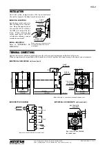
COMPONENT IDENTIFICATION
Body
Base Socket
x10
HI SET.
(%)
X1
x10
LO SET.
(%)
X1
123
45
67890
123
45
67890
123
45
67890
123
45
67890
K
•UNIT
Specifications
Input Resistor
■
FRONT PANEL CONFIGURATION
Lo LED
Lo Setpoint Rotary Switch (×1%)
Lo Setpoint Rotary Switch (×10%)
Hi Setpoint Rotary Switch (×1%)
Hi Setpoint Rotary Switch (×10%)
Hi LED
HI SET
[%]
x1
x10
LO SET
[%]
x1
x10
• Explanations
Hi and Lo setpoint rotary switches are used to set the alarm
setpoints.
The Hi and Lo LED, turn on when the coil for each relay is
energized.
• Examples
For setting the relay to trip above 80% of the full-scale input
signal, set the Hi rotary switch (×10) to “8”, while the switch
(×1) to “0”.
DC ALARM
(CE, rotary switch adjustment)
MODEL
KSL2
5-2-55, Minamitsumori, Nishinari-ku, Osaka 557-0063 JAPAN
Phone: +81(6)6659-8201 Fax: +81(6)6659-8510 E-mail: info@m-system.co.jp
EM-3614 Rev.2 P. 1 / 3
INSTRUCTION MANUAL


