background image


Technical Manual 

Version 1.00 


RTCU LX4 pro


Advanced Industrial M2M/IoT Gateway


Summary of Contents for LOGIC io

Page 1: ...Technical Manual Version 1 00 RTCU LX4 pro Advanced Industrial M2M IoT Gateway...

Page 2: ...X32L NX32 for Linux architecture that embraces many new technologies and at the same time maintains full backward compatibility which ensures already implemented and tested NX32 applications can execu...

Page 3: ...g Outputs 17 RS232 port 18 RS485 Port 18 RS485 port 1 19 RS485 port 2 19 1 Wire bus 19 Wired M Bus 20 Wireless M Bus optional 20 User interface 21 Graphical LCD display 21 Keypad 23 System Menu 23 LED...

Page 4: ...re aware of such errors or inaccuracies or that we are unaware of these as a result of gross negligence and Logic IO Aps has failed to eliminate these errors or inaccuracies for this reason This produ...

Page 5: ...ard and NAT services TLS SSL support with full certificate management TLS SSL supporting all significant TCP protocols such as RCH FTP SMTP MQTT and sockets Hardware assisted encryption authentication...

Page 6: ...ized audio system Transfer store and play audio Digitized cellular audio DTMF support for Interactive Voice Response applications Storage Internal flash drive with up to 64 MByte capacity Persistent m...

Page 7: ...hnical Manual V1 00 Advanced Industrial M2M IoT Gateway Logic IO ApS Ph 45 7625 0210 Holmboes All 14 Fax 45 7625 0211 8700 Horsens Page 7 of 39 Email support logicio com Denmark www logicio com RTCU L...

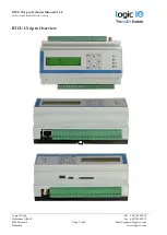
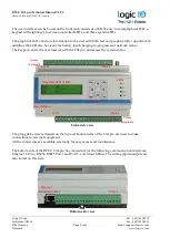
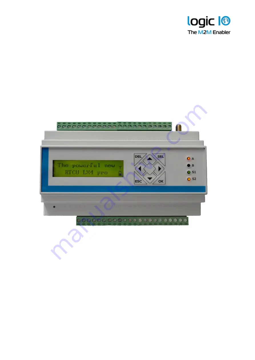
Page 8: ...battery level charging in progress and network status The keypad can let the user interact with the LX4 pro and access the system menu Front side view The pluggable screw terminals on the top and bott...

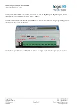
Page 9: ...f the RTCU LX4 pro has connectors for power digital inputs digital outputs and an SMA female connector for an external cellular antenna The SD card reader four DIP switches and the mini B USB connecto...

Page 10: ...13 39 DOUT GND RS232 TXD 14 40 SGND RS232 RDX 15 41 DIN1 S0IN1 RS232 RTS 16 42 DIN2 S0IN2 RS232 CTS 17 43 DIN3 S0IN3 M Bus 18 44 DIN4 S0IN4 M Bus 19 45 DIN5 IGN AOUT 1 20 46 DIN6 AOUT2 21 47 DIN7 AIN...

Page 11: ...2 24 AIN3 Analog input 3 25 AIN4 Analog input 4 26 AGND Analog Ground Pin 27 49 overview Pin Name Description 27 PGND Power ground negative connection 28 SUPP Power supply positive connection 29 SUPP...

Page 12: ...to the PGND pin There are three different ground labels for ground connections Supply ground PGND signal ground SGND and analog ground AGND The signal and the analog grounds are filtered from the pow...

Page 13: ...from the power supply connected to the DOUT SUPP and DOUT GND The DOUT GND is connected with the system GND internally The RTCU unit offers advanced power management that can enable one or more output...

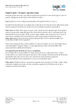
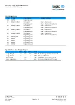
Page 14: ...ower apply will also wake up the unit if it is in power down mode or WaitForEvent mode with power apply and or ignition selected for wakeup Please note Digital inputs 6 8 do not work as high speed IO...

Page 15: ...put 2 Digital input 2 Row 2 Position S Row 2 Position N default 43 DIN3 S0IN3 S0 input 3 Digital input 3 Row 3 Position S Row 3 Position N default 44 DIN4 S0IN4 S0 input 4 Digital input 4 Row 4 Positi...

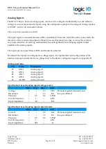
Page 16: ...ires and significant fast changing signals routed parallel to the analog signals The inputs are low pass filtered ESD and transient protected By default the inputs are configured as voltage inputs For...

Page 17: ...ficant fast changing signals routed parallel to the analog signals In current mode the specifications for the analog output are only valid for a maximum load is maximum of 250 The inputs are low pass...

Page 18: ...ted to the RS485 bus The maximum cable length for the RS485 bus is according to the EIA TIA 485 A standard max 1000m 100kbit this limit is highly influenced by the quality of the cable signaling rate...

Page 19: ...B 2 RS485 inverting signal for RS485 port 2 11 SGND Signal ground 1 Wire bus The 1 Wire bus is available on the pluggable screw terminals All 1 Wire communication goes through a single connection and...

Page 20: ...US M Bus signal 19 M BUS SGND M bus ground Signal ground Specification for the M Bus Min Typ Max Unit Bus idle voltage 36 VDC Protected against short circuiting Slave devices 20 Speed 300 9600 bps Wir...

Page 21: ...pro is a 144x32 pixel graphical display A range of display functions is available for making graphical and alphanumerical presentations of the data user interaction with menus etc By default the disp...

Page 22: ...bile phones One bar means low signal strength and four bars represent high signal strength No signal strength bars indicate that the cellular interface is powered up but is not connected to the networ...

Page 23: ...out the use of the buttons System Menu The system menu can be used to view the status of the device To access the system menu it must be enabled either by using displaySysMenuEnable to open it immedia...

Page 24: ...ation name and version If the name is too large it will automatically scroll to show the entire name Mobile network status The arrows in the upper right corner show that this menu has submenus availab...

Page 25: ...e User LED A and B LED A and B is composed of two individually controllable LEDs LED named A on the front consists of LED 1 green and LED 2 red LED named B on the front consists of LED 3 green and LED...

Page 26: ...RTCU IDE to obtain the fault log Alternating Fast Slow red3 The device has lost its firmware This can only happen if during a firmware upgrade the RTCU device loses power or the communication is lost...

Page 27: ...ry to use a small thin object with a diameter of approx 2 mm for example a straightened out paper clip for this purpose By activating the switch shortly the RTCU device will perform a full reset If th...

Page 28: ...e both the power supply and cables can handle the high current Whenever a power failure has occurred the battery will be charged to establish the capacity thus making the battery ready for the next po...

Page 29: ...pro device contains a standard Mini SIM card reader located inside the device The SIM card reader is a lid based reader with a mechanical lock system to secure the SIM card installation Please refer t...

Page 30: ...for example if the SD CARD is often replaced Commercial grade SD CARDs should not be used in applications where the media s potential failure is considered mission critical For applications that exten...

Page 31: ...m Denmark www logicio com Product Identification Label with Barcode The RTCU LX4 pro product identification is found on the device s exterior and contains a unique serial number in readable form and b...

Page 32: ...alues marked with are averaged and should be considered guidelines as they may vary depending on the cellular signal strength Note Power consumption from the battery 3 8V The table below shows detaile...

Page 33: ...d USB cable have been removed Release the tap on the right side by pulling out on the top part of the encapsulation below the tap e g using a screwdriver and begin lifting the right side Carefully ope...

Page 34: ...39 Email support logicio com Denmark www logicio com Configuration The following figure shows the location of the jumpers when the lid is removed The blue shaded boxes show the default state of the ju...

Page 35: ...sition V Aout 2 current mode selected Aout 2 voltage mode selected Digital input Din 1 Position S Position N Din 1 S0 mode selected Din 1 normal mode selected Din 2 Position S Position N Din 2 S0 mode...

Page 36: ...M Card Please refer to Appendix A to get inside access to the device The SIM card reader is a lid based type with a mechanical lock for the insertion of a mini SIM card Open the hinged lid on the SIM...

Page 37: ...U LX4 pro products include several open source software tools This open source software is governed by the terms and conditions of the applicable open source license You are bound by the terms and con...

Page 38: ...5 A per channel Short circuit ESD Inductive kick back protected up to 20 mH User supplied power source 8 x digital inputs Logic high 8 to 40 VDC Logic low 5 to 3 VDC Impedance 3 3kohm 12V 4 x IEC6205...

Page 39: ...Technical Manual V1 00 Advanced Industrial M2M IoT Gateway Logic IO ApS Ph 45 7625 0210 Holmboes All 14 Fax 45 7625 0211 8700 Horsens Page 39 of 39 Email support logicio com Denmark www logicio com EN...

Reviews: