background image

1

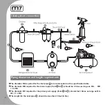
1. The maximum recommended air pressure during operation must not exceed 90 psi 

(6.3bar). Higher air pressure may create unsafe operating conditions for the tool and 

the user.

2. The compressed air should be cooled and have a water filter installed at the outlet 

end of the compressor. Even with a water filter installed, some water may still 

condense in the piping or hose and will enter the tool mechanism causing premature 

damage to the tool. Therefore, it is recommended to install an air filter-lubricator 

device somewhere between the tool and the compressor.  

3. Always use an air compressor of the proper capacity to operate each tool.
4. Clean the hose with a blast of compressed air before connecting the hose to the air 

tool. This will prevent   both moisture and dust inside the hose from entering the tool 

and causing possible rust or malfunction.

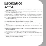
1. Using these tools in any potentially explosive environment is strictly prohibited.

2. It is always recommended that these types of tools must be operated when standing 

on a solid or firm location.

3. Always use these tools in a well ventilated area.

4. Slipping, stumbling and falling are the major causes of potential serious injury, 

therefore, a clean and clutter free surface in the working area before operating the 

tools is strongly recommended.

Read this manual carefully before installing, operating, 

servicing or repairing.

Working environment:

Air supply and connection requirements:

Summary of Contents for PA-111

Page 1: ...o operate each tool 4 Clean the hose with a blast of compressed air before connecting the hose to the air tool This will prevent both moisture and dust inside the hose from entering the tool and causi...

Page 2: ...t pipe is recommended on the specification table The diameter B required for the branch pipe from to should be 2 times as large as A B 2 x A The diameter C required for the primary air supply from to...

Page 3: ...ns of the rivets to be used are compatible with this tool 7 Check the protection against the ejecting of rivet stem in place and is operative 8 Make certain to stand on a solid or firm location and ke...

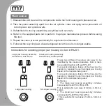
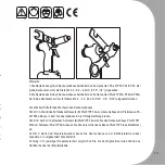
Page 4: ...201 Large jaw housing assembly PA 201P03 P04 P05 Small jaw housing assembly PA 201P03A P04A P05A Large jaw housing Small jaw housing These two different housings are easy to be identified by the inter...

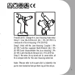
Page 5: ...ill the Jaw Housing Coupler PA 201P07 with the supplied Multi Wrench B PA 201P55 and disassemble the Jaw Housing PA 201P03 with the Multi Wrench A PA 201P54 Step3 Reverse the procedure to assemble all...

Page 6: ...sseur 3 Utilisez un compresseur avec une capacit adapt e pour chaque outil 4 Nettoyez le tuyau d alimentation avec une d charge d air avant chaque utilisation Ceci vitera que de l humidit et ou des im...

Page 7: ...ils 6 S assurer avant l utilisation que les sp cifications des rivets utilis s sont compatibles cet outil 7 S assurer que la protection contre les clous rompus est bien en place et fonctionnel 8 Il es...

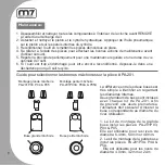
Page 8: ...sez le dans une d chetterie pour qu il soit recycl Guide pour s lectionner les bonnes m choires sur la pi ce PA 201 Montage grande m choire PA 201P03 P04 P05 Montage petite m choire PA 201P03A P04A P0...

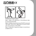
Page 9: ...201P55 pour retirer la cloche frontale PA 201P02 Etape 2 Rattacher le raccord de la buse PA 201P07 avec la cl multi fonction PA 201P55 et d sassembler la buse PA 201P03 avec la cl multi fonction A PA...

Page 10: ...d erh htem Materialverschlei f hren kann 2 Die Druckluftzufuhr soll durch den in der Anlage eingebauten Lufttrockner abgek hlt werden und am Druckluftabgang durch den installierten Filter gefiltert we...

Page 11: ...Sie sicher dass f r ausreichenden Schutz gegen herabfallende Sp ne und Partikel w hrend des Betriebs gesorgt ist 8 Sie sollen auf einem festen und sicheren Arbeitsbereich stehen und auf Ihre K rperhal...

Page 12: ...r das Werkzeug sollte immer in regelm igem Abstand ausgef hrt werden 6 Nach der endg ltigen Abnutzung des Werkzeugs befolgen Sie alle Umweltschutzrechtlinien f r die Abfallentsorgung bzw Abfallbeseiti...

Page 13: ...h uses Schritt 1 Anhand des Schraubenschl ssels B PA 201P55 das vordere Geh use der Pistolenase PA 201P02 abl sen in dem Sie das Geh use in die Uhrzeigerrichtung drehen Schritt 2 Auch mit demselben Sc...

Page 14: ...ci n no debe exceder de 90 psi 6 3bar Una presi n de aire mayor podr a crear condiciones de operaci n no seguras para la herramienta y el usuario 2 El aire comprimido debe ser enfriado y tener un filt...

Page 15: ...arse sean compatibles con esta herramienta 7 Revise que el protector contra la expulsi n del v stago del remache est en su lugar y funcionando 8 Aseg rese de pararse sobre un lugar s lido o firme y ma...

Page 16: ...as las leyes de reciclaje y desechos una vez que esta herramienta sea desechada Instrucciones para seleccionar el alojamiento de mand bula chuck apropiado en el item PA 201 Conjunto del alojamiento de...

Page 17: ...4 0mm 3 2mm 2 4mm Procedimiento para cambiar el ensamblaje de la mand bula Paso1 Use la Multi Llave B PA 201P55 para quitar la Cubierta Frontal PA 201P02 Paso2 Mantenga sujeto el acople de la cubiert...

Page 18: ...m tica 1 A press o m xima de trabalho n o deve ultrapassar 90 psi 6 3 bar Press es mais altas podem danificar a ferramenta e machucar o operador 2 O ar comprimido deve ser resfriado e filtrado na sa d...

Page 19: ...fica es de material e di metro dos rebites s o compat veis com essa ferramenta 7 Verifique se a prote o contra restos de rebite est montada e em opera o 8 Trabalhe somente sobre um piso ou base sufici...

Page 20: ...a o acima descritas periodicamente 6 Procure reciclar essa ferramenta e ou suas partes se as mesmas j n o forem mais teis Instru es para sele o e troca do suporte de pin as da PA 201 Suporte maior par...

Page 21: ...s de 2 4 mm 3 2 mm e 4 00 mm Procedimentos para trocar o suporte de montagem pin as Passo 1 Use a chave especial PA 201P55 para remover o alojamento frontal PA 201P02 Passo 2 Trave a pe a PA 201P07 co...

Page 22: ...22 1 2 3 4 1 90 psi 6 3 2 3 4...

Page 23: ...23 1 2 3 4 5 6 7 8 9 10 11 12 13...

Page 24: ...24 1 2 3 4 5 6 PA 201 PA 201P03 P04 P05 PA 201P03A P04A P05A PA 201...

Page 25: ...25 1 PA 201P03 P04 P05 6 4 6 0 4 8 2 PA 201P3A P4A P5A 4 0 3 2 2 4 1 B PA 201P55 PA 201P02 2 PA 201P07 B PA 201P55 PA 201P03 PA 201P54 3...

Page 26: ...doporu en tlak vzduchu b hem provozu nesm p ekro it 6 3 bar 90 psi Vy tlak vzduchu m e zp sobit nebezpe n provozn podm nky pro n ad a u ivatele 2 Stla en vzduch by m l b t zbaven vlhkosti pomoc su i...

Page 27: ...i perky 6 Ujist te se e v echny parametry pou van ch n t jsou kompatibiln s n tovac mi kle t mi 7 Chra te se p ed mo n m odl t v n m stonk n t b hem provozu 8 P i provozu n ad st jte na pevn m podklad...

Page 28: ...l 5 Opakujte cel proces dr by pravideln 6 Jakmile ji nen n ad pou iteln i te se z kony t kaj c mi se likvidace odpadu Pokyny pro v b r spr vn elisti PA 201 Mont velk elisti PA 201P03 P04 P05 Mont male...

Page 29: ...n ty rozm r 4 0mm 3 2mm or 2 4mm Proces v m ny elist Krok 1 pou ijte multi kl B PA 201P55 k demont i eln ho v ka PA 201P02 Krok 2 dr te spojku t la elisti PA 201P07 pomoc multi kl e B PA 201P55 a dem...

Page 30: ...30 1 2 3 4 1 90psi 2 3 4...

Page 31: ...31 1 2 3 4 5 6 7 8 9 10 11 12 13...

Page 32: ...32 1 2 3 4 5 6 PA 201 PA 201P03 P04 P05 PA 201P03A P04A P05A 1 2 PA 201 3 PA 201P03 P04 P05 3 6 4mm 6 0mm or 4 8mm 4 PA 201P3A P4A P5A 3 4 0mm 3 2mm or 2 4mm...

Page 33: ...33 1 P55 2 2 P55 2 P54 1A 3 P55 1 54 7 55 3 4 5 6 2 4 5 3 6 7 3 7...

Page 34: ...ess stainless aluminum aluminum aluminum steel steel steel stainless steel stainless stainless aluminum aluminum aluminum steel steel steel stainless steel stainless stainless aluminum aluminum alumin...

Page 35: ...stainless aluminum aluminum aluminum steel steel steel stainless steel stainless stainless RIVET 2 5 3 0 4 0 5 0 6 4 7 2 8 0 2 4 3 2 4 8 RIVET DIAMETER MM PA 321 PA 401MV PA 301MV PA 401V Rivet D1 Man...

Page 36: ...3 1 48 1 5 10 79 7 0 3 1045 16 2 4 4 8 6 3 1 48 1 5 10 79 7 0 3 1045 16 2 4 4 8 6 3 1 48 1 5 10 79 7 0 3 1185 22 2 4 4 8 6 3 1 48 1 5 10 79 7 0 4 695 16 2 4 4 0 6 3 0 67 1 25 10 79 7 0 3 695 16 2 4 4...

Page 37: ...6 3 1 48 1 5 10 79 7 0 3 1185 22 2 4 4 8 6 3 1 48 1 5 10 79 7 0 4 695 16 2 4 4 0 6 3 0 67 1 25 10 79 7 0 3 695 16 2 4 4 0 6 3 0 5 1 05 10 79 7 0 3 1650 9 6 3 1 5 1 55 10 82 0 0 8 1700 18 6 4 8 0 6 3...

Page 38: ...67 1 25 3 8 79 7 0 3 695 16 2 4a4 0 90 0 5 1 05 3 8 79 7 0 3 1650 9 90 1 5 1 55 3 8 82 0 0 8 1700 18 6 4a8 0 90 2 9 1 75 3 8 79 7 0 8 1860 26 4 8 6 4 6 3 2 88 3 0 10 82 0 0 8 1603 14 2 4 6 4 6 3 2 32...

Page 39: ...EC and its amendment and is manufactured and tested according to the following standards EN ISO 11148 1 EN ISO 15744 EN ISO 20643 A1 Declared in Taichung Taiwan Dated 2013 06 01 Jonney Chen Declared...

Page 40: ...llage 2006 42 EC et ses amendements et qu ils ont t fabriqu s et test s selon les standards suivants EN ISO 11148 1 EN ISO 15744 EN ISO 20643 A1 D clar Taichung Taiwan Date 2013 06 01 Jonney Chen Decl...

Page 41: ...eren nderungen und dass es hergestellt wird und nach den folgenden Normen gepr ft wird EN ISO 11148 1 EN ISO 15744 EN ISO 20643 A1 Erkl rt in Taichung Taiwan Datum 2013 06 01 Jonney Chen Erkl rt von Q...

Page 42: ...06 42 EC y sus enmiendas y ha sido fabricado y probado de acuerdo a los siguientes est ndares EN ISO 11148 1 EN ISO 15744 EN ISO 20643 A1 Declarado en Taichung Taiwan Fecha 2013 06 01 Jonney Chen Decl...

Page 43: ...EC e seus anexos tendo sido fabricado e testado de acordo com a s seguinte s normas EN ISO 11148 1 EN ISO 15744 EN ISO 20643 A1 Declarada em Taichung Taiwan Datada de 2013 06 01 Jonney Chen Declarada...

Page 44: ...N ISO 15744 EN ISO 20643 A1 Taichung Taiwan 2013 06 01 Jonney Chen Mighty Seven International Co Ltd No 70 25 Ching Qunag Rd Wu Jih Shiang Taichung City 41466 Taiwan www mighty seven com King Tony Fra...

Page 45: ...e n sleduj c ch standard EN ISO 11148 1 EN ISO 15744 EN ISO 20643 A1 Prohl eno v Taichung Taiwan Dne 2013 06 01 Jonney Chen Deklarov no QA Manager Manufacturer Mighty Seven International Co Ltd No 70...

Page 46: ...46 Air Hydraulic Riveter ltem No PA 111...

Page 47: ...g 1 39 PA 111P39 Plug 1 40 PA 111P40 O Ring 1 41 PA 111P41 Nipple 1 42 PA 111T42 O Ring 2 pcs 1SET 43 PA 111P43 Connector 1 44 PA 111P44 Retaining Ring 1 45 PA 111P45 Cylinder 1 46 PA 111P46 Pin 1 47...

Page 48: ...48 Air Hydraulic Riveter ltem No PA 201...

Page 49: ...eturn Spring Inner 1 1 PA 201P46 Return Spring Outer PA 201P21 Rear Gland 1 1 PA 201P47 O Ring PA 201P22 Collecting Tube 1 1 PA 201P48 Lock Nut PA 201P23 Hanger Ring 1 1 set 1 PA 201P49 Plug Bolt 3 8...

Page 50: ...50 Air Hydraulic Riveter ltem No PA 201V...

Page 51: ...1 32 PA 201VT32 O Ring 2 pcs 1SET 33 PA 201VP33 Lock Nut 1 34 PA 201VP34 O Ring 1 35 PA 201VP35 Cylinder Cap 1 36 PA 201VP36 Trigger Rod 1 37 PA 201VP37 Trigger Lever 1 NO INDEX NO DESCRIPTION Q TY 38...

Page 52: ...52 Air Hydraulic Riveter ltem No PA 211...

Page 53: ...PA 211P21 Frame Cap 1 22 PA 211P22 Safety Cap 1 23 PA 211P23 Hanger Clip 1 24 PA 211P24 Air Valve Seal 1 25 PA 211P25 O Ring 1 26 PA 211P26 Valve Seat 1 27 PA 211P27 O Ring 1 NO INDEX NO DESCRIPTION...

Page 54: ...54 Air Hydraulic Riveter ltem No PA 211TS...

Page 55: ...e Seat 1 27 PA 211TSP27 O Ring 1 NO INDEX NO DESCRIPTION Q TY 28 PA 211TST28 Ring Seal Washer 2 pcs 1SET 29 PA 211TSP29 Air Piston Rod 1 30 PA 211TSP30 O Ring 1 31 PA 211TSP31 Air Piston 1 32 PA 211TS...

Page 56: ...56 Air Hydraulic Riveter ltem No PA 301...

Page 57: ...23 Return Spring Small 1 1 PA 301P49 Bolt Plug PA 301P24 Seal 1 1 1 1 1 PA 301P50 Pin PA 301P25 O Ring 1 1 PA 301P51 Spring Pin PA 301P26 Valve Seat 1 1 PA 301P52 Lock Screw PA 301P27 O Ring 1 1 PA 30...

Page 58: ...58 Air Hydraulic Riveter ltem No PA 301V...

Page 59: ...A 301VP34 O Ring 1 35 PA 301VP35 Cylinder Cap 1 36 PA 301VP36 Trigger Rod 1 37 PA 301VP37 Trigger Lever 1 NO INDEX NO DESCRIPTION Q TY 38 PA 301VP38 Valve Tube 1 39 PA 301VP39 Air Cylinder 1 40 PA 301...

Page 60: ...60 Air Hydraulic Riveter ltem No PA 301MV...

Page 61: ...MVP32 O RING 1 33 PA 301MVP33 O RING 1 34 PA 301MVP34 B RING 1 35 PA 301MVP35 O RING 1 36 PA 301MVP36 LOCK NUT 1 NO INDEX NO DESCRIPTION Q TY 37 PA 301MVP37 AIR PISTON ROD 1 38 PA 301MVP38 AIR CYLINDE...

Page 62: ...62 Air Hydraulic Riveter ltem No PA 321...

Page 63: ...321P25 O Ring 1 26 PA 321P26 Valve Seat 1 27 PA 321P27 O Ring 1 28 PA 321T28 Valve Collar Washer 2 pcs 1set 29 PA 321P29 Air Piston Rod 1 30 PA 321P30 O Ring 1 31 PA 321P31 Air Piston 1 NO INDEX NO DE...

Page 64: ...64 Air Hydraulic Riveter ltem No PA 401V...

Page 65: ...Cylinder Cap 1 36 PA 401VP36 Trigger Rod 1 37 PA 401VP37 Trigger Liver 1 38 PA 401VP38 Valve Tube 1 39 PA 401VP39 Air Cylinder 1 40 PA 401VP40 Frame Lock Nut 1 42 PA 401VP42 Valve Cap Nut 1 43 PA 401...

Page 66: ...66 Air Hydraulic Riveter ltem No PA 401MV...

Page 67: ...33 PA 401MVP33 PENTAGON SEAL 1 34 PA 401MVP34 B RING 1 35 PA 401MVP35 O RING 1 36 PA 401MVP36 LOCK NUT 1 NO INDEX NO DESCRIPTION Q TY 37 PA 401MVP37 AIR PISTON ROD 1 38 PA 401MVP38 AIR CYLINDER 1 39...

Page 68: ...68 Air Hydraulic Riveter ltem No PB 2402...

Page 69: ...1 PB 2402P21 Frame Cap 1 22 PB 2402P22 Return Tube 1 23 PB 2402P23 Hanger Clip 1 24 PB 2402P24 Air Valve Seal 1 25 PB 2402P25 O Ring 1 26 PB 2402P26 Valve Seat 1 27 PB 2402P27 O Ring 1 NO INDEX NO DES...

Page 70: ...70...

Page 71: ...71...

Page 72: ......

Reviews: