background image

MW250

Processes

Description

Gas Metal Arc (MIG) Welding
Flux Cored Arc (FCAW)

Welding

Arc Welding Power Source And Wire

Feeder

OM-154 501L

August 1998

®

Summary of Contents for MW50

Page 1: ...MW250 Processes Description Gas Metal Arc MIG Welding Flux Cored Arc FCAW Welding Arc Welding Power Source And Wire Feeder OM 154 501L August 1998...

Page 2: ......

Page 3: ...Installing Welding Gun 8 3 5 Electrical Service Requirements 8 3 6 Positioning Jumper Links 9 3 7 Connecting Input Power 10 3 8 Installing Wire Spool And Adjusting Hub Tension 11 3 9 Threading Weldin...

Page 4: ......

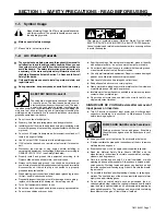
Page 5: ...s connected to a properly grounded receptacle outlet D When making input connections attach proper grounding conduc tor first double check connections D Frequently inspect input power cord for damage...

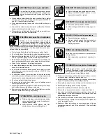
Page 6: ...welding wire at contact tip when not in use D Wear oil free protective garments such as leather gloves heavy shirt cuffless trousers high shoes and a cap D Remove any combustibles such as a butane lig...

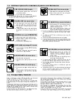
Page 7: ...maintained D Keep high frequency source doors and panels tightly shut keep spark gaps at correct setting and use grounding and shielding to minimize the possibility of interference ARC WELDING can cau...

Page 8: ...is a human health hazard However studies are still going forth and evidence continues to be examined Until the final conclusions of the research are reached you may wish to minimize your exposure to e...

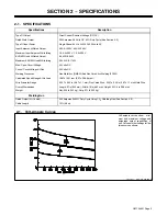
Page 9: ...trol Circuit Voltage At Gun 24 Volts DC Welding Processes Gas Metal Arc GMAW And Flux Cored Arc Welding FCAW Calculated Speed Range At No Load 128 To 1051 ipm 3 2 To 266 9 mpm Wire Diameter Range 030...

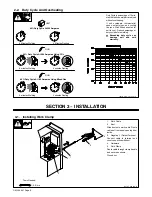
Page 10: ...e At 200 Amperes 6 Minutes Welding 4 Minutes Resting UNIT GUN 6 minutes Welding 4 minutes Resting GUN 6 minutes Welding 4 minutes Resting 60 Duty Cycle At 200 Amperes Using CO2 60 Duty Cycle At 180 Am...

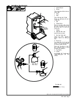
Page 11: ...face is vertical 9 Gas Hose Connection Fitting has 5 8 18 right hand threads Obtain and install gas hose 10 Flow Adjust Typical flow rate is 20 cfh cubic feet per hour Check wire manufactur er s reco...

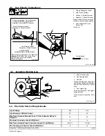
Page 12: ...Cored Wires FCAW Process Drive Assembly Becomes Negative S 144 449 D Tools Needed 3 4 11 16 in 3 4 Installing Welding Gun 1 Wire Drive Assembly 2 Gun Securing Knob 3 Gun End Loosen securing knob Inser...

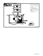
Page 13: ...ge available at site 1 Jumper Links Access Door Open door 2 Jumper Link Label 3 Input Voltage Jumper Link Move jumper link to match input voltage Close and secure access door Close side door 1 2 200 V...

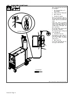
Page 14: ...onductor and input conductors in conduit or equivalent between wall receptacle and deenergized line disconnect device Connect grounding conductor first then line input conductors Be sure grounding con...

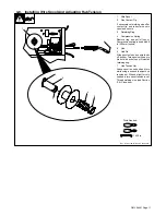
Page 15: ...mpression spring is used with 8 in 200 mm spools 5 Hub 6 Hub Pin Slide spool onto hub so wire feeds off bottom Turn spool until hub pin fits hole in back of spool Reinstall retaining ring 7 Hub Tensio...

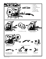
Page 16: ...54 251 S 0627 A 6 in 150 mm 4 in 102 mm Tighten WOOD Open pressure assembly Pull and hold wire cut off end Push wire thru guides into gun continue to hold wire Close and tighten pressure assembly and...

Page 17: ...ge Step 6 of Low range and Step 1 of High range overlap 3 Pilot Light 4 Power Switch Use switch to turn unit On and Off The pilot light comes on when unit is turned on 5 Work Clamp Use wire brush or s...

Page 18: ...when wire speed is between 90 and 670 ipm Use Full position when wire speed is be tween 150 ipm and 1030 ipm 2 Voltage Range Selector Place switch in desired position See inside rear cover for settin...

Page 19: ...Weld Terminals Repair Or Replace Cracked Cables And Cords 6 Months Blow Out Or Vacuum Inside Remove drive roll and carrier Apply light coat of oil or grease to drive motor shaft 5 2 Circuit Breaker CB...

Page 20: ...e Loosen screw Slide tip as close to drive rolls as possible without touching Tighten screw 3 Anti Wear Guide Install guide as shown 4 Drive Roll Install correct drive roll for wire size and type 5 Dr...

Page 21: ...Disconnect gun first Tools Needed 3 8 in 3 8 in Head Tube 3 8 in Remove nozzle contact tip and liner collet Blow out gun casing Gun Feeder Connector Remove liner To Reassemble Gun Install contact tip...

Page 22: ...6 Low weld output Connect unit to proper input voltage or check for low line voltage see Section 3 7 Wire Drive Gun Trouble Remedy Electrode wire feeding stops during welding Straightengun cable and...

Page 23: ...OM 154 501 Page 19 SECTION 6 ELECTRICAL DIAGRAM SB 173 544 E Figure 6 1 Circuit Diagram For Welding Power Source...

Page 24: ...09 970 Rectifier Bracket 143 810 Rear Panel 169 654 Tank Bracket 044 426 Cable Clamp 8 602 387 Cylinder Chain 9 146 165 Side Panel LH 10 089 899 Latch 11 146 167 Side Panel 12 134 464 Warning Label 13...

Page 25: ...13 185 643 Strip mtg LH RH 14 184 584 Capacitor 185 642 Insulator 15 186 355 Contactor 114 786 Link 16 134 201 PC Card Stand Off 17 173 002 Motor Speed Control Card 18 012 658 Fuse mintr gl slo blo 2...

Page 26: ...ener 7 085 244 Cupped Washer 8 010 231 Spring 9 085 243 Knob 10 166 071 Pressure Lever 11 079 634 Hinge Pin 12 151 828 Cotter Hair Pin 13 173 616 Cover motor 14 173 435 Motor 15 079 633 Fitting hose 3...

Page 27: ...TIONAL Part No Item No Description 1 3 4 5 6 7 8 9 12 1 11 1 10 13 14 15 2 2 16 17 Ref ST 801 148 Included w Item 7 Figure 7 4 MWG 23B Figure 7 1 Item22 Table 7 1 Drive Roll And Wire Guide Kits IMPORT...

Page 28: ......

Page 29: ...ormal wear 3 Equipment that has been modified by any party other than manufacturer or equipment that has been improperly installed improperly operated or misused based upon industry standards or equip...

Page 30: ...Style Number Contact your Distributor for Welding Supplies and Consumables Options and Accessories Personal Safety Equipment Service and Repair Replacement Parts Owner s Manuals Circuit Diagrams Cont...

Reviews: