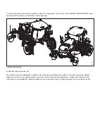
background image

M1170

NT5

Windrower

Operator

s Manual

215922 Revision A

Original Instruction

The Harvesting Specialists.

Summary of Contents for M1170NT5

Page 1: ...M1170NT5 Windrower Operator s Manual 215922 Revision A Original Instruction The Harvesting Specialists...

Page 2: ...il 2022 2022 MacDon Industries Ltd The information in this publication is based on the information available and in effect at the time of printing MacDon Industries Ltd makes no representation or warr...

Page 3: ...que el producto Tipo de m quina 2 Nombre y modelo 3 N meros de serie 4 cumple con todas las disposiciones per nentes de la directriz 2006 42 EC Se u lizaron normas armonizadas seg n lo dispuesto en el...

Page 4: ...a persoanei mputernicite pentru ntocmirea declara iei 6 Numele i semn tura persoanei autorizate pentru ntocmirea c r ii tehnice Benedikt on Ziedesel Manager General MacDon Europe GmbH Hagenauer Stra e...

Page 5: ...xplains this warranty should have been provided to you by your Dealer Damage resulting from any of the following conditions will void the warranty Accident Misuse Abuse Improper maintenance or neglect...

Page 6: ...CN 61684 1 12 Understanding Safety Signs page 18 Added safety decal MD 310977 ECN 61684 3 15 1 Operator Console Buttons page 72 Added topic Technical Publications 4 6 8 Adjusting Header Raise and Lowe...

Page 7: ...o which the whole body is subjected ranges from 0 423 to 0 707 m s2 as measured in the vertical direction on a representative machine during typical operations and analyzed in accordance with ISO 5008...

Page 8: ...and crop conditions and the type of platform used The average of the maximum values of the A weighted sound pressure level inside the operator s station is 64 6 dB A as measured in accordance with Di...

Page 9: ...ndrower serial number plate A is located on the left side of the main frame near the walking beam 1036695 A A MacDon M1170 Figure 2 Windrower Serial Number Location France Only Windrowers sold in Fran...

Page 10: ...ine Serial Number Location Engine serial number plate A is located on top of the engine cylinder head cover Engine Serial Number ____________________________ Model Year _____________________________ 2...

Page 11: ...1 9 2 Engine Electronics 14 1 10 Safety Signs 15 1 10 1 Installing Safety Decals 15 1 11 Safety Decal Locations 16 1 12 Understanding Safety Signs 18 Chapter 2 Product Overview 29 2 1 Definitions 29 2...

Page 12: ...eater Shut Off Valve 61 3 10 2 Air Distribution 61 3 10 3 Climate Controls 61 3 11 Operator Amenities 63 3 12 Sound System 65 3 12 1 AM FM CD DVD Radio with Bluetooth Wireless Technology 65 Activating...

Page 13: ...hine Information Pages 103 Accessing Windrower Information 104 Accessing Header Information 105 Accessing Software Information 106 Accessing Performance Information 107 Chapter 4 Operation 109 4 1 Own...

Page 14: ...1 D1X or D1XL Series Draper Header 166 Attaching Draper Header Supports 166 Attaching D1X or D1XL Series Draper Header 167 Connecting D1X or D1XL Series Draper Header Hydraulics 173 Detaching D1X or...

Page 15: ...Draper Header Run Screens 225 Run Screen 1 226 Run Screen 2 227 4 7 10 Swath Compressor 227 Swath Compressor Controls 227 Locking and Unlocking the Swath Compressor 229 Chapter 5 Maintenance and Serv...

Page 16: ...tening Drive Wheel Nuts 262 5 6 2 Tightening Caster Wheel Nuts 263 5 6 3 Tightening Caster Wheel Anti Shimmy Dampeners 263 5 6 4 Tensioning Air Conditioner Compressor Belts 264 5 6 5 Changing Engine G...

Page 17: ...System 297 5 10 6 Changing Engine Gearbox Lubricant 298 5 11 Every 500 Hours or Annually 300 5 11 1 Maintaining Fuel Filters 300 Removing Primary Fuel Filter 300 Installing Primary Fuel Filter 301 Re...

Page 18: ...8 Replacing Engine Fan Drive Belt 338 Tensioning Air Conditioner Compressor Belts 339 Replacing Air Conditioner Compressor Belts 339 5 15 5 Engine Speed 340 5 15 6 Lighting 340 Aligning Headlights Eng...

Page 19: ...Chapter 7 Troubleshooting 383 7 1 Engine Troubleshooting 383 7 2 Electrical Troubleshooting 387 7 3 Hydraulics Troubleshooting 388 7 4 Header Drive Troubleshooting 389 7 5 Traction Drive Troubleshoot...

Page 20: ...215922 xviii Revision A 8 4 Engine Fault Codes 443 Index 469 Lubricants Fluids and System Capacities 483 TABLE OF CONTENTS...

Page 21: ...y Alert Symbols The safety alert symbol indicates important safety messages in this manual and on safety signs on the machine 1000915 Figure 1 1 Safety Symbol This symbol means ATTENTION BECOME ALERT...

Page 22: ...ded will result in death or serious injury WARNING Indicates a potentially hazardous situation that if not avoided could result in death or serious injury It may also be used to alert against unsafe p...

Page 23: ...oves Wet weather gear Respirator or filter mask 1000005 Figure 1 3 Safety Equipment In addition take the following precautions Be aware that exposure to loud noises can cause hearing impairment Wear s...

Page 24: ...functionality and or safety of the machine It may also shorten the machine s service life To avoid injury or death from the unexpected startup of the machine ALWAYS stop the engine and remove the key...

Page 25: ...ervicing and or disconnecting the machine Ensure that all components are tight and that steel lines hoses and couplings are in good condition before applying pressure to hydraulic systems Keep hands f...

Page 26: ...ulic system operates under extremely high pressure Makeshift repairs can fail suddenly and create hazardous conditions 1001207 Figure 1 12 Hydraulic Pressure Hazard Wear proper hand and eye protection...

Page 27: ...is correctly seated on the rim before inflating it If the tire is not correctly positioned on the rim or is overinflated the tire bead can loosen on one side causing air to escape at high speed and w...

Page 28: ...flush it with cool clean water for 5 minutes Call a doctor immediately If electrolyte is spilled or splashed on one s clothing or their body neutralize it immediately with a solution of baking soda an...

Page 29: ...rmed on the machine IMPORTANT Ensure that the windrower is parked on a level surface the ignition is turned off and the key is removed before disconnecting anything The following items need to be disc...

Page 30: ...ors insert the end of a small 3 6 mm 1 8 1 4 in blade screwdriver into the connector s locking tab Gently pry upward no more than 6 mm 1 4 in to unlock the connector tab and then pull the connector aw...

Page 31: ...rs A Two round connectors C1 and C2 Location Under the cab 1017627 A Figure 1 25 Roof Connectors Roof connectors A Four connectors C10 C12 C13 and C14 Location Under the cab at the base of the left ca...

Page 32: ...ors C25 and C26 Location Under the center of the frame just behind the front cross member IMPORTANT To connect the circular Deutsch connectors without bending the pins fully align the plug with the re...

Page 33: ...ocedure in the Starting Engine section of the operator s manual Following the correct procedure will help prevent major damage to engine components and prevent personal injury To ensure that the jacke...

Page 34: ...e to the electronic unit injectors Do NOT touch the harness connector for the electronic unit injectors while the engine is operating Failure to follow this instruction could result in personal injury...

Page 35: ...l part on which a safety sign was installed is replaced ensure that the repair part displays the current safety sign Replacement safety signs are available from Dealer Parts Department 1 10 1 Installi...

Page 36: ...A 1 11 Safety Decal Locations Safety signs are factory installed in many different locations on the windrower 1034222 A G F T U S E E C P Q R J H J C E E L M N R Q D K B B B V Figure 1 31 Safety Sign...

Page 37: ...t H 166824 Decal Fill rate J 166832 Decal High pressure fluid K 166829 Decal Caution balance L 166834 Decal Warning starter jump M 166835 Decal Warning battery explode N 166836 Decal Warning battery b...

Page 38: ...t or for use by children The Operator and the Passenger must wear their safety belts when operating or riding in the machine Keep all other riders off of the machine 1000685 Figure 1 33 MD 166425 MD 1...

Page 39: ...before starting the engine and during its operation Keep riders off the machine Keep all shields in place and stay clear of moving parts Disengage the header drive put the transmission in Neutral and...

Page 40: ...ng lubricating cleaning or unplugging the machine Engage the safety locks to prevent the lowering of the header or the reel before servicing the header when it is in the raised position Use a slow mov...

Page 41: ...stall a MacDon approved weight box onto the windrower Refer to the windrower and header operator s manuals for instructions on safely towing the header Adjust the drive wheel width and walking beam wi...

Page 42: ...skin Hydraulic oil penetrating the skin can result in serious injury gangrene or death Do NOT approach hydraulic oil leaks Do NOT use any part of your body to check for oil leaks Relieve the pressure...

Page 43: ...ry and do NOT connect boosting or charging cables incorrectly Refer to the operator s manual for battery boosting and charging procedures 1000693 Figure 1 42 MD 166836 MD 166836 Battery acid hazard WA...

Page 44: ...rd WARNING To prevent injury Do NOT operate the engine with the engine hood open Stop the engine and remove the key before opening the engine hood 1000688 Figure 1 44 MD 166838 MD 166838 Hot surface h...

Page 45: ...the machine Do NOT make sudden sharp changes to your speed while turning such as hard braking When travelling on steep slopes Reduce the machine s speed and lower the header Move the ground speed leve...

Page 46: ...h into the pinch area 1037136 Figure 1 48 MD 306179 306180 306181 MD 306179 306180 306181 Header crushing hazard DANGER To prevent injury or death from the fall of a raised header Fully raise the head...

Page 47: ...drive wheel legs and walking beam for narrow road transportation to reduce the overall windrower width as required per local regulations Make certain everyone is clear of machine before starting the...

Page 48: ......

Page 49: ...st fluid through the exhaust aftertreatment system DK Double knife DKD Double knife drive DOC Diesel oxidation catalyst DWA Double Windrow Attachment EEC Eco engine control Engine forward Windrower op...

Page 50: ...preformed threads or forms its own thread when inserted into a mating part SDD Single draper drive SK Single knife SKD Single knife drive Soft joint A flexible joint made by use of a fastener in whic...

Page 51: ...ing Standard Starter Wet type Lighting package 12 lights 4 halogen road 8 LED work 2 LED work lights also used for egress Traction Drive Type Hydrostatic infinitely variable motors via electric shift...

Page 52: ...settings deck shift positions on draper Options External booster spring up to 2 per side Deluxe Cab Suspension 4 point spring shock Dimensions Width 1767 mm 69 6 in Depth 1735 mm 68 3 in Height 1690...

Page 53: ...ns Drive Narrow Transport Bar 540 65R30 Caster Suspended 16 5 L 16 1 with independent suspension Frame and Structure Dimensions Refer to 2 3 Windrower Dimensions page 35 Frame to ground crop clearance...

Page 54: ...r Double Windrow DWA Drive Option4 3 Charge Pressure Pump for Pumps 4 5 6 and 7 4 Knife Disc Drive Closed Loop System 5 Fan Drive and Lift Functions Open Loop System 6 Traction Drive Tandem Pump Left...

Page 55: ...wer Dimensions Field Road Field Road Field Road A 3300 mm 130 in B 4290 mm 168 7 8 in C 5752 mm 226 7 16 in C 5140 mm 202 3 8 in D 3834 mm 150 15 16 in D 3489 mm 137 23 64 in E 1150 mm 45 9 32 in F 34...

Page 56: ...s main components 1034048 A B C D E F G H J J K L M N E F M Figure 2 3 Cab Forward View A Header Lift Leg B Header Float Springs C Operator s Station D Windshield Wiper E Turn Signals Hazard Lights F...

Page 57: ...Forward View A Caster Wheel B End Marker Rod C Rear Deflectors D Engine Compartment Hood E Work Light F Field Lights G Turn Signals Hazard Lights H Marker Lights J Field Road Lights K Mirror L Drive...

Page 58: ......

Page 59: ...tion of travel 3 1 Console The console contains controls to operate the windrower as well as amenities for the Operator 1012699 A B C D E Figure 3 1 Console The console position is adjustable to suit...

Page 60: ...215922 40 Revision A 1012705 A Figure 3 3 Console Fore Aft 2 Adjust only fore aft as follows a Loosen nuts A under the console b Move the console as required c Tighten nuts A OPERATOR S STATION...

Page 61: ...restart the header 3 2 2 Engine and Transmission The windrower is powered by a diesel engine The transmission then uses power from the engine to move the windrower The engine will NOT start when the...

Page 62: ...description and the location of each adjustment Some seat features are only available with the deluxe cab option 3 3 1 Armrest The standard and deluxe seats are equipped with one armrest 1019743 A B...

Page 63: ...rest angle Rotate knob A counterclockwise to decrease the armrest angle 3 3 3 Suspension and Height Use the controls on the side of the seat to adjust the height and stiffness of the seat suspension 1...

Page 64: ...ator s Seat Fore Aft Position Controls 1 Pull lever A up to release 2 Move the seat forward or rearward 3 Release lever A 3 3 5 Fore Aft Isolator Control Use the controls on the seat to lock the seat...

Page 65: ...p to release 2 Position the seat back as desired 3 Release lever A 3 3 7 Lumbar Support Use the controls on the back of the seat adjust the stiffness of the seat s back 1012789 A Figure 3 10 Operator...

Page 66: ...s Turn knob A counterclockwise to increase vertical dampener Turn knob A clockwise to decrease vertical dampener 3 3 9 Cushion Tilt Deluxe Cab Only Use the controls on the front of the seat to adjust...

Page 67: ...eluxe seat s lateral isolation lockout 3 3 12 Heating Cooling Deluxe Cab Only Use the controls on the side of the seat to adjust the heating cooling of the deluxe operator s seat WARNING Do NOT use th...

Page 68: ...ing and Cooling Controls Seat heating cooling switch A Move the switch forward for COOL Move the switch backward for HEAT Heating cooling high low off switch B Move the switch up for HIGH Move the swi...

Page 69: ...use the training seat when operating the windrower in engine forward mode The training seat is NOT intended as a passenger seat or for use by children Use the seat belt whenever you are operating the...

Page 70: ...g seat occupant s seat belt is securely fastened Never wear a seat belt loosely or leave any slack in the belt system Never wear the belt in a twisted condition or pinched between the seat structural...

Page 71: ...215922 51 Revision A To release the seat belt 1012792 A A B B Figure 3 18 Seat Belt 1 Push the red button on the end of buckle B 2 Separate buckle B from metal eye A OPERATOR S STATION...

Page 72: ...g Column 1 Hold onto the steering wheel lift handle A and move the steering column forward or backward into the desired position 2 Release handle A to lock the steering column in position To adjust th...

Page 73: ...lighting mode is selected NOTE When in engine forward mode field lights B do NOT turn on An LED on the switch changes from OFF to amber when the switch is on The high beam switch has a blue LED that...

Page 74: ...ork lights E Rear swath lights F NOTE For adjustment procedures refer to Aligning Headlights Cab Forward page 342 3 7 2 Cab Forward Lighting Road Road lights are used to light up the area ahead of the...

Page 75: ...rward mode 3 7 3 Engine Forward Lighting Road Road lights are used to light up the area ahead of the windrower 1012725 A B C Figure 3 26 Road Light Button The following lights are functional when ROAD...

Page 76: ...high beams are activated in engine forward mode Marker Lights E NOTE To align headlights A refer to Aligning Headlights Engine Forward page 340 3 7 4 Tail Beacon Lighting Beacons and tail lights are...

Page 77: ...e 3 30 Turn Signal Hazard Button Switches A activate the left and right turn signals Press the switches again to turn the selected signal off NOTE Turn signals can also be controlled with the REEL DIS...

Page 78: ...58 Revision A 1034262 C C C Figure 3 31 Windrower Lighting Top View Amber turn signals hazard lights C NOTE Amber turn hazard repeater lights are located on the side of each hazard placard OPERATOR S...

Page 79: ...ers are NOT on pressing and holding window washer button C will spray washer fluid onto both windows and both wipers will turn on When the button is released the washer fluid stops but both wipers con...

Page 80: ...a rear view when the windrower is in cab forward mode Two manually adjustable mirrors B provide a rear view in the engine forward mode Mirror assemblies are designed to fold back if accidentally struc...

Page 81: ...m the engine coolant 1015484 A A Figure 3 36 Heater Shut Off Valve Valve A must be open to provide heat to the cab but can be closed for maximum cooling 3 10 2 Air Distribution Cab air distribution is...

Page 82: ...ted Windshield defog defrost switch D The windshield defog defrost operates when air conditioning A C switch E ON Air conditioning A C switch E Controls the A C system The A C operates with the blower...

Page 83: ...operator s console has the following features Auxiliary power outlets A USB jack B Utility tray under armrest C Utility tray D Cup holder E 1014912 A Figure 3 40 Window Shades Window shades Retractabl...

Page 84: ...215922 64 Revision A 1014914 A Figure 3 42 Coat Hook Coat hook Coat hook A is located above the training seat to the left of the operator s seat OPERATOR S STATION...

Page 85: ...structions for information on the supported file types 1014920 A B Figure 3 43 Radio and Speakers Radio A and two speakers B are factory installed in the cab headliner The radio operates in AM FM CD D...

Page 86: ...on the receiver to allow mobile device pairing MOTOROLA MENU A B C D Figure 3 47 Bluetooth Radio 1 Press POWER button A to turn the radio on 2 Press and hold VOL SEL knob B for 2 seconds MENU is displ...

Page 87: ...2 Press POWER button A to turn the radio ON This will set the radio to Bluetooth discover mode if the Bluetooth feature has been activated If not refer to the radio operator s manual for instructions...

Page 88: ...cated under the front left corner of the cab floor when facing cab forward 1012729 A Figure 3 49 Console The horn is activated by pushing button A located on the console Sound the horn three times pri...

Page 89: ...also locks the doors and the tool box in the left platform 1012732 A B Figure 3 51 Engine Controls Throttle A Controls the engine speed range MAX Push the lever forward MIN Pull the lever back Harves...

Page 90: ...eader is engaged and is adjustable in 100 rpm increments Activate this feature by using EEC button A on the operator s console The EEC symbol will display on the Harvest Performance Tracker HPT screen...

Page 91: ...und speed lever GSL B Controls speed and direction of movement F Forward N NEUTRAL PARK Engages neutral interlock and applies park brake when steering locked in center R Reverse Hazard warning lights...

Page 92: ...Delivery E Draper Double Windrow Attachment DWA Speed F Cab Forward Field Lights G Beacon Lights H Turn Signals K Hazard Lights L Clearance Lights M Road Lights N High Beams P Windshield Defog Defrost...

Page 93: ...ADER ENGAGE switch A down NOTE Although not required it is good practice to move the throttle lever back to IDLE before engaging the header drive 3 16 2 Header Drive Reverse Button The header drive re...

Page 94: ...Figure 3 58 GSL Function Groups GSL controls front One Touch Return position switch A One Touch Return position switch B One Touch Return position switch C Reel or disc speed D also operates turn sig...

Page 95: ...eed Lever To lower the header slowly press A lightly To lower the header quickly press A fully To raise the header slowly press C lightly To raise the header quickly press C fully To tilt the header d...

Page 96: ...er is not in use 1012761 A B Figure 3 62 GSL Reel and Disc Speed Switch Press and hold button A to increase the reel or disc speed Press and hold button B to decrease the reel or disc speed Release th...

Page 97: ...wath compressor raise lower Double Windrow Attachment DWA speed Knife speed Draper speed Reel speed Reel height Reel fore aft Disc speed To program the One Touch Return buttons press and hold button A...

Page 98: ...Deck Shift Float Presets Buttons to control header functions are located on the console 1014967 A B C Figure 3 66 Header Deck Shift Buttons A Right Side Delivery B Center Delivery C Left Side Delivery...

Page 99: ...refer to the section in this manual that is specific to your header Conveyor Speed Adjustment Buttons Buttons to control header functions are located on the console 1014968 A B Figure 3 68 Operator s...

Page 100: ...ons are located on the console 1030170 A B C D E F Figure 3 70 Operator s Console Shortcut Buttons The following functions have been assigned to the function buttons on the operator s console F1 A Flo...

Page 101: ...556 A Figure 3 71 Operator s Console HPT A is located on the operator s console 3 17 1 Harvest Performance Tracker Screen Layout The appearance and functions of the Harvest Performance Tracker HPT dep...

Page 102: ...formation displayed depends on the type of header attached to the windrower and which run screen is active Run screen 1 Displays reel draper knife disc or auger speed and pressure alarm point and inde...

Page 103: ...rower fault Telltales are amber or red in color accompanied by a symbol for the fault Telltales display a short description B of the fault 1019632 A Figure 3 77 Maintenance Indicator Required maintena...

Page 104: ...elects functions or menu items Scroll and select functions are duplicated on the ground speed lever GSL controls Unless otherwise specified both buttons will perform the same function When SELECT is u...

Page 105: ...u structure Press HOME button B on the HPT to return to the last selected run screen or header disengaged screen 1014574 A B Figure 3 81 GSL Shift and Back Buttons Press BACK button A on the GSL to re...

Page 106: ...plays the main menu After a menu is open soft keys 1 5 also function as buttons within menus QuickMenu System The QuickMenu system allows you to change certain windrower and header functions directly...

Page 107: ...fe Speed page 218 Access maintenance information Refer to 3 17 8 Machine Information Pages page 103 Adjust auto speed settings Refer to 4 7 Operating with D1X or D1XL Series Draper Header page 203 Def...

Page 108: ...knob B or the GSL SELECT button not shown to select the highlighted icon NOTE Pressing the corresponding soft key will also work The following submenus are accessible through the main menu Information...

Page 109: ...s Submenu Icons Screen Settings Icon A displays the following submenu icons Brightness and Volume B Time and Date C Language and Units D Reset to Defaults E 1016127 A B C D E Figure 3 89 Windrower Set...

Page 110: ...pe B Hours Used C Total Acres D 1019721 Figure 3 91 Header Setup Menu After the header is selected the HEADER SETUP menu opens which includes Cut Width Raise Lower Rates Attachments 1019634 A Figure 3...

Page 111: ...gnostics Icon A displays the following submenu icons Windrower Fault Codes B Engine Fault Codes C Inputs Outputs D Can Network E 1014659 A B C D E Figure 3 95 Engine Aftertreatment Icon and Soft Keys...

Page 112: ...llow faults displayed on the bottom line indicate that a failure has occurred and the machine should be serviced as soon as possible to diagnose the failure Figure 3 96 HPT Run Screen Displaying Fault...

Page 113: ...ale icons A will appear on screen in a row To display a detailed description of each fault use the HPT scroll select knob to select the icon 3 17 3 Setting up Harvest Performance Tracker Screen The sc...

Page 114: ...and the Harvest Performance Tracker HPT scroll knob For instructions refer to 3 17 2 Navigating Harvest Performance Tracker Display page 84 if required 2 Scroll to SCREEN icon A and select it 3 Scroll...

Page 115: ...e to SETUP Menu C by pressing soft key 5 A and HPT scroll knob B For instructions refer to 3 17 2 Navigating Harvest Performance Tracker Display page 84 if required 1033561 A B Figure 3 102 Brightness...

Page 116: ...ime and Date 4 Scroll through the available options on the HPT display select the desired option and rotate the scroll knob to make adjustments Setting Language and Units of Measurement The language a...

Page 117: ...nversion Chart page 407 for a comprehensive list of U S and metric units Resetting to Factory Defaults The Harvest Performance Tracker HPT can be reset to the defaults setting 1016140 A B C Figure 3 1...

Page 118: ...uage English Units USA Eco engine control speed 4 and 6 cylinders have different speeds Max cab forward speed 14 mph Max engine forward speed 27 mph Header speed settings Header alarm pressures Knife...

Page 119: ...ere are any active fault codes 1016140 A B C Figure 3 109 Opening the Main Menu 2 Press soft key 5 A to open the main menu or press SHIFT and SELECT on the ground speed lever GSL 3 Use Harvest Perform...

Page 120: ...igured for 600 65R28 bar tires If the windrower is equipped with a different type of tire you will need to change this setting Setting the proper tire size ensures that the HPT accurately tracks the w...

Page 121: ...either exit the menu by pressing the BACK button or exit the TIRE SELECTION page by pressing the HOME button NOTE Pressing the BACK or HOME buttons will save the settings to memory 3 17 6 Enabling Nar...

Page 122: ...All header functions are factory set to the unlocked position but certain functions can be locked to prevent changes This feature can be used to maintain preferred settings when there are multiple Op...

Page 123: ...ELECT to activate the lock 3 17 8 Machine Information Pages The Harvest Performance Tracker can display various pages of information 1014644 A B C D E Figure 3 122 Information Icon and Information Sub...

Page 124: ...GSL scroll wheel not shown 3 Press HPT scroll knob B or the GSL SELECT button not shown to select the highlighted INFORMATION icon 1014721 A Figure 3 124 Windrower Information Submenu Icon 4 Scroll to...

Page 125: ...gure 3 126 Opening the Main Menu 1 Press soft key 5 A to open the main menu 2 To scroll to INFORMATION icon C use HPT scroll knob B or the ground speed lever GSL scroll wheel not shown 3 Press HPT scr...

Page 126: ...ble from run screen 3 For instructions refer to Viewing Performance Data page 137 NOTE The acre count is active when the header is engaged and the header height is in the lower 50 of its range Accessi...

Page 127: ...tension module not shown Accessing Performance Information The performance information menu displays the accumulated data over time and the accumulated data per field 1014684 A B C Figure 3 132 Openin...

Page 128: ...nd is not resettable the other displays data accumulated per field B and is resettable The performance information menu displays the following information Engine hours C Engine idle time D Average loa...

Page 129: ...e to operate the windrower for however short a time or distance ensure that they have been instructed in its safe and proper use Review this manual and all other relevant safety information with all t...

Page 130: ...sole for windrower operation 1019378 A B C D E F G H J K L M N P Q R S T U V W X Y Figure 4 1 Windrower Operating Symbols A Signal Lights B Hazard Lights C Forward D Neutral E Reverse F Road Lights G...

Page 131: ...Reel Fore Aft G Draper H Draper Pressure J Draper Speed K Header Height L Header Tilt M Header Float N DWA Raise P DWA Lower Q Disc R Disc Pressure S Disc Speed T DEF U SCR Conditioning Manual V SCR...

Page 132: ...Wait to Start J Engine Coolant Temperature K Engine Intake Air Filter L Engine Oil Pressure M Engine Oil Level N Engine Oil Filter P Engine Coolant Level Q Engine Air Intake Temperature R Hydraulic O...

Page 133: ...les Heavy gloves A respirator or filter mask Wet weather gear 1000005 Figure 4 5 Safety Equipment Protect against noise Wear suitable hearing protection such as ear muffs or ear plugs to protect again...

Page 134: ...tank For instructions refer to 5 7 5 Checking Engine Coolant Level page 274 NOTE If overheating problems occur check for coolant leaks Perform the break in inspections specified in 5 2 1 Break in Ins...

Page 135: ...Coolant Cycling Air conditioners use coolant in the system to remove the heat from inside the cab IMPORTANT Perform the following steps whenever the machine is first started after storage for more th...

Page 136: ...to help prevent condensation in the tank DANGER To prevent bodily injury or death from the unexpected startup of the machine always stop the engine and remove the key from the ignition before leaving...

Page 137: ...Diesel Exhaust Fluid Tank The symbol inside the diesel exhaust fluid DEF gauge on the Harvest Performance Tracker HPT display will signal when DEF level is low DANGER To prevent bodily injury or death...

Page 138: ...refer to 5 1 1 Storing Lubricants and Fluids page 231 Figure 4 9 DEF Tank 5 Replace filler cap A and turn clockwise until tight Checking Engine Oil Level Check the engine oil level frequently and watc...

Page 139: ...g Engine You can start the engine with the operator s seat in the cab forward or the engine forward position DANGER Only start the engine in a well ventilated space Ensure that there are no bystanders...

Page 140: ...he battery disconnect relay The Harvest Performance Tracker HPT goes into a boot up sequence that takes approximately 40 seconds The following items trigger a wake up signal for the console Key switch...

Page 141: ...igure 4 14 Operator Controls 3 Move GSL A into PARK C 4 Turn the steering wheel until it locks It may be possible to move the steering wheel slightly in the locked position IMPORTANT Do NOT attempt to...

Page 142: ...een 10 Turn the IGNITION switch to crank position A NOTE When the engine starts and the header is not engaged the HPT displays header disengaged page B IMPORTANT Do NOT operate the starter for longer...

Page 143: ...able 4 1 Engine Start Troubleshooting Problem Solution Controls are not in the NEUTRAL position Move the GSL to NEUTRAL Move the steering wheel to the locked centered position Disengage the HEADER swi...

Page 144: ...the maximum reel draper and ground speeds The EEC feature is turned ON or OFF by pressing EEC button A on the operator s console EEC will only be available when the header is engaged The GREEN LEAF s...

Page 145: ...y 1015077 A Figure 4 22 HPT Display Engine Temperature Gauge Normal engine operating temperature is indicated when the needle is in the green range of gauge A If the engine temperature exceeds 105 C 2...

Page 146: ...mance of the aftertreatment system by increasing exhaust temperatures in order to remove the buildup of crystallized DEF Automatic cleaning occurs any time during machine operation as long as the INHI...

Page 147: ...4 25 HPT Display 4 To select manual SCR conditioning press soft key 4 A next to MANUAL SCR CONDITIONING icon B and hold it for 3 seconds High exhaust system temperature HEST icon C appears highlighted...

Page 148: ...e Delivery E Draper Double Windrow Attachment DWA Speed F Cab Forward Field Lights G Beacon Lights H Turn Signals K Hazard Lights L Clearance Lights M Road Lights N High Beams P Windshield Defog Defro...

Page 149: ...steering wheel for easier exit and re entry Lock the cab door if you are leaving the windrower unattended 1014972 A B Figure 4 27 Platforms and Doors A swing away platform with stairs A is provided on...

Page 150: ...o open the QuickMenu system 1014825 A Figure 4 29 HPT Display 2 To scroll to GROUND SPEED LIMIT selectable area A use the HPT scroll knob to move the red cursor 3 Press the HPT scroll knob to select a...

Page 151: ...beep and display a red P symbol to confirm that the parking brake is engaged 1 Park the windrower on a level surface 1012967 A B C Figure 4 31 Operator Station 2 If the operator s seat is in the cab f...

Page 152: ...talled by a MacDon Dealer The GSL has been pre wired at the factory with a switch For more information refer to 6 2 1 Automated Steering Systems page 378 Driving in Reverse in Cab Forward Mode WARNING...

Page 153: ...Figure 4 35 Engine Forward Seat Faces Engine If necessary swivel the operator s station to engine forward position as follows CAUTION Park on a level surface with the ground speed lever GSL in the PAR...

Page 154: ...n engages the latch to secure the operator s station in the new position 3 Ensure the seat belt is fastened 4 Start the engine if not already running For instructions refer to Starting Engine page 119...

Page 155: ...ger exists a Set GSL A to NOT MORE THAN HALF maximum forward speed Driving in Reverse in Engine Forward Mode WARNING Back up slowly Hold the steering wheel at the bottom and turn the wheel in the dire...

Page 156: ...To stop the turn slowly turn the steering wheel back to its centered position Stopping Move the ground speed lever on the console to the park position to stop WARNING Do NOT move the ground speed leve...

Page 157: ...f it will be idling for longer than 5 minutes NOTE Brakes are automatically engaged when steering wheel is locked in PARK position 4 Turn the ignition key counterclockwise to OFF position Viewing Perf...

Page 158: ...ect RESET to reset the sub acres to zero and return to the same highlighted sub acres Select EXIT or press the BACK or HOME button to dismiss the message without resetting the sub acres In this screen...

Page 159: ...drower is designed to be driven on the road with the engine facing forward to provide better visibility for the Operator and improved stability for the machine Windrowers sold in North America can als...

Page 160: ...ces and slow moving vehicle signs 4 Adjust the interior rear view mirror and clean the windows 5 Ensure the header if attached is fully raised and the header lift safety props are engaged 6 If the wid...

Page 161: ...e the windrower is moving Anticipate acceleration or deceleration if changing maximum speed while moving 13 Slowly push throttle A to full forward operating speed WARNING Check to be sure all bystande...

Page 162: ...Cab Forward Mode The M1170NT5 Windrower is capable of being driven on the road in cab forward mode with or without a header attached but at a reduced speed under restricted conditions and only for mo...

Page 163: ...e sure you have good visibility out of the cab and that motorists are able to see the header lights 5 Raise the header if attached enough to clear common obstacles and then engage the header lift safe...

Page 164: ...han or equal to 51 km h 30 mph the HPT will display a warning message SLOW DOWN with an audible alert Move GSL closer to NEUTRAL to reduce speed With the header removed steering control is reduced if...

Page 165: ...Placard 5 Rotate left signal light placard A to the down horizontal position before driving in narrow transport mode 1034108 A B Figure 4 56 Transport Locks 6 At the front of the windrower rotate walk...

Page 166: ...operator s console to activate the narrow transport controls The HPT will display an Important Message B and sound an alarm 1034104 A B Figure 4 58 Narrow Transport Control Page 10 Press F5 button A o...

Page 167: ...and hold REEL AFT button B on the GSL to retract the drive wheel legs 13 Bring the windrower to a complete stop and place the GSL in PARK 1034120 A B Figure 4 60 Narrow Transport Controls 14 Press F6...

Page 168: ...y pressing button F5 or F6 again which ever is active The exit transport operation warning will display on the HPT NOTE Press F5 or F6 on the console or HOME or RETURN on the HPT to cancel transport o...

Page 169: ...he key from the ignition before leaving the operator s seat for any reason 1 Ensure the narrow transport function is enabled on the Harvest Performance Tracker HPT For instructions refer to 3 17 6 Ena...

Page 170: ...B Figure 4 67 Transport Locks 6 At the front of the windrower rotate walking beam lockout valve handle A to the open position in line with the valve 7 Remove lockout pins B from the sliding drive whe...

Page 171: ...utton A on the operator s console to activate the narrow transport controls The HPT will display an Important Message B and sound an alarm 1034104 A B Figure 4 69 Narrow Transport Control Page 10 Pres...

Page 172: ...ss and hold REEL FORE button A on the GSL to extend drive wheel legs 13 Bring the windrower to a complete stop and place the GSL in PARK 1034120 A B Figure 4 71 Narrow Transport Controls 14 Press F6 b...

Page 173: ...page by pressing button F5 or F6 again whichever is active The exit transport operation warning will display on the HPT NOTE Press F5 or F6 on the console or HOME or RETURN on the HPT to cancel transp...

Page 174: ...6 Figure 4 76 Towing a Header WARNING A windrower without a header or weight box must NOT be used to tow headers due to reduced traction and possible loss of control For towed equipment without brakes...

Page 175: ...structions refer to Attaching D1X or D1XL Series Draper Header page 167 1015593 A B C D Figure 4 79 Draper Header Support 2 Convert the header to transport mode For instructions refer to header operat...

Page 176: ...ift legs slightly 10 Shut down the engine and remove the key from the ignition 11 Install locking pin C into the pocket and secure it with hairpin D Repeat for the opposite leg NOTE The pins were prev...

Page 177: ...y for short distances on level ground and at slow speed DANGER When the windrower s wheel drives are disengaged turned inward the windrower s brakes and steering will be nonfunctional and the windrowe...

Page 178: ...drive NOTE Engaging the wheel drives may require rocking the wheels slightly 4 3 7 Storing Windrower Follow these steps to prepare your windrower for storage at the end of the season WARNING NEVER us...

Page 179: ...thoroughly leaving excess grease on fittings to keep moisture out of bearings Apply grease to the exposed threads and the sliding surfaces of components 12 Remove the batteries For instructions refer...

Page 180: ...while operating in engine forward mode enable the secondary disc brake system by pressing BUTTON C A on the ground speed lever GSL and then gradually moving the GSL back to the neutral position NOTE O...

Page 181: ...econdary braking system 1013381 Figure 4 89 One Touch Return Buttons on GSL The One Touch Return buttons A and B always save header height settings but the following settings can also be saved dependi...

Page 182: ...n that shows corresponding letter A on the screen for the preset Secondary braking system 1037447 A B Figure 4 91 Secondary Braking System Button on GSL Pressing button C A while in the engine forward...

Page 183: ...r Position D Telltales A B C D E F H J K M G L Figure 4 93 Left Gauge Cluster The HPT display is separated into the following zones Left gauge cluster Ground speed A Maximum ground speed B Engine rpm...

Page 184: ...controller software MCAK203587P or later required to accurately display changes in draper speed Run screen 3 Displays fuel per hour acre acres per hour and sub acres per hour resettable Run screen 4...

Page 185: ...nance Indicator Required maintenance indicator An amber indicator A is displayed 50 hours before required maintenance is due The indicator only displays when header is disengaged The indicator flashes...

Page 186: ...nt bodily injury or death from the unexpected startup of the machine always stop the engine and remove the key from the ignition before leaving the operator s seat for any reason If not installed atta...

Page 187: ...ttaching Draper Header Supports page 166 1 Shut down the engine and remove the key from the ignition 2 Extend the windrower transport into field mode Refer to Extending Wheels Field Mode page 149 1016...

Page 188: ...If you are lowering the header lift legs WITHOUT a header or weight box attached to the windrower fully release the tension in header float springs A If prompted by the Harvest Performance Tracker HP...

Page 189: ...18911 A B C D E F Figure 4 106 GSL Switches A Reel Down B Reel Up C Header Tilt Down D Header Tilt Up E Header Down F Header Up 11 Windrowers equipped with the self aligning center link kit a Press HE...

Page 190: ...equipped with the self aligning center link kit a Adjust the position of center link cylinder A with the switches on the GSL until hook B is above the header attachment pin IMPORTANT Hook release C mu...

Page 191: ...the self locking mechanism to function If the hook release is open in the up position manually push it down after the hook engages the pin d Check that center link A is locked onto the header by pulli...

Page 192: ...4 112 Header Leg 19 Install pin B through the header leg ensuring that the pin engages the U bracket in the draper header support and secure it with hairpin A Repeat this step on the other side of the...

Page 193: ...eader IMPORTANT To prevent contamination of the hydraulic system use a clean rag to remove dirt and moisture from all hydraulic couplers 1016803 A B C Figure 4 115 Hydraulic Hose Management System 1 P...

Page 194: ...Push knob B on the hydraulic receptacle and pull handle C fully away from the windrower 9 Open cover D and position the coupler onto the receptacle Align the pins in the coupler with the slots in han...

Page 195: ...pler onto the receptacle Align the pins in the coupler with the slots in handle C and push the handle toward the windrower so that the coupler locks onto the receptacle and knob B snaps out 1015750 Fi...

Page 196: ...e machine always stop the engine and remove the key from the ignition before leaving the operator s seat for any reason 1 Lower the header fully 2 Shut down the engine and remove the key from the igni...

Page 197: ...Remove any debris that may have accumulated on the receptacle Close cover E 1015768 A B C D E Figure 4 126 Draper Reel Multicoupler 8 Push lock button B and pull handle C to disengage multicoupler A...

Page 198: ...Forward Platform 14 Pull platform A towards the cab until it stops and the latch is engaged 1019477 A C B Figure 4 130 Hydraulic Hose Management System 15 Disconnect hose management system A from win...

Page 199: ...n header 1000771 A B C D Figure 4 132 Header Stand 17 Remove the header leg pin B by removing the hairpin A from header leg on both sides 18 Lower header stand D by pulling spring loaded pin C Release...

Page 200: ...NGER Ensure that all bystanders have cleared the area 1019480 A B C Figure 4 135 GSL 22 Start the engine 23 Remove header float when prompted by the Harvest Performance Tracker HPT NOTE If not prompte...

Page 201: ...t Performance Tracker Before operating the header ensure that the Harvest Performance Tracker HPT settings are appropriate for your header 1018929 A B Figure 4 138 Header Settings 1 Navigate to the SE...

Page 202: ...ecalibration is required in the following circumstances The HPT is replaced A position sensor is replaced Sensor readouts are erratic A pump has been replaced A new header type or attachment is connec...

Page 203: ...con C 4 Press HPT scroll knob B or the GSL SELECT button not shown to activate the settings menu options 1016143 A B Figure 4 141 Windrower Settings Icon and Calibration Submenu Icon 5 Scroll to WINDR...

Page 204: ...to begin the calibration process The display on the screen changes to show that the calibration procedure has started NOTE If the engine speed is less than 1500 rpm prior to starting the calibration...

Page 205: ...m that the hydraulic system is free of any restrictions and is in working order Confirm that the throttle is working Check the engine codes to confirm that engine is not de rated or throttle inhibited...

Page 206: ...n C 4 Press HPT scroll knob B or the GSL SELECT button not shown to activate the settings menu options 1016143 A B Figure 4 149 Windrower Settings Icon and Calibration Submenu Icon 5 Scroll to WINDROW...

Page 207: ...ng the calibration process calibration will stop and a message will appear on the screen indicating that a sensor is out of range 1014670 A Figure 4 152 Calibration Screen 8 When stage one of the cali...

Page 208: ...e NOTE If the voltage of any sensor falls below its acceptable range during calibration a message appears after completing the calibration with a list of sensors reporting out of range voltages Adjust...

Page 209: ...ng the operator s seat and always engage the safety props before going under the machine for any reason WARNING Check to be sure all bystanders have cleared the area 1 Start the engine 1014786 A Figur...

Page 210: ...t scooping or pushing soil IMPORTANT Configure the header float setting to be as light as possible while limiting the amount of bouncing produced by the header Doing so will reduce the amount of wear...

Page 211: ...Lift Cylinder Fully Retracted Draper 335 380 N 75 85 lbf with stabilizer transport wheels raised if equipped 8 Restart the engine and adjust float as required For instructions refer to Setting Float...

Page 212: ...ange the header weight at the cutterbar by approximately 91 kg 200 lb Adjust the float in increments of 0 05 to optimize field performance 7 Press soft key 3 D to remove or resume the header float Cut...

Page 213: ...A to adjust the float setting and press the knob when finished IMPORTANT Float adjustments of 1 0 out of 10 change the header weight at the cutterbar by approximately 91 kg 200 lb Adjust the float in...

Page 214: ...may be installed but will be nonfunctional for certain headers Engaging and Disengaging the Header The HEADER ENGAGE switch engages and disengages the header drive DANGER Ensure that all bystanders ha...

Page 215: ...switch B is in the ENGAGED position 3 When you are ready to return to forward operation release HEADER DRIVE REVERSE button A to stop the header 4 Push down HEADER ENGAGE switch B to OFF position The...

Page 216: ...se HEADER HEIGHT CONTROLS E and F Adjust the header angle as follows To decrease flatten the header angle operate HEADER TILT UP switch C on the GSL to retract the cylinder To increase steepen the hea...

Page 217: ...on handle A to release the locking device and lift the hook off the header pin 1015884 A B C Figure 4 171 Center Link Hook 4 Lower handle A into the locked position 5 Push up on lock pin B only not a...

Page 218: ...5 0 or less to avoid contacting the cab roof After the reel fore aft automatically moves you will then have to manually adjust the fore aft For instructions about operating the reel fore aft refer to...

Page 219: ...rator s console NOTE This can also be done with the One Touch Return For instructions refer to One Touch Return Buttons page 77 Double Windrow Attachment Conveyor Speed 1014968 A B Figure 4 178 Operat...

Page 220: ...osition and speeds For instructions refer to One Touch Return Buttons page 77 4 6 8 Adjusting Header Raise and Lower Rates The header raise and lower rates control how fast a header is raised or lower...

Page 221: ...gure 4 183 Set Up Header Menu List 4 Press the HPT scroll knob HEADER SETUP page A appears NOTE The F4 shortcut button on the operator s console also will display the HEADER SETUP page 5 Scroll to RAI...

Page 222: ...rate Scroll through the RAISE FIRST RAISE SECOND and LOWER FIRST LOWER SECOND menu selections and program the following GSL buttons HEADER RAISE D half button press adjusts stage one slow rate full b...

Page 223: ...rops and conditions For procedures for controlling header height header tilt and float refer to 4 6 Operating Header page 189 4 7 2 Adjusting Reel Fore Aft Position Optimize header performance based o...

Page 224: ...greater than 5 0 lower the reel height and or header height to a value of 7 0 or less The reel fore aft will automatically move forward to 5 0 or less If you increase the header height to greater tha...

Page 225: ...sting Reel Fore Aft Position page 203 4 7 4 Leveling Header The windrower lift linkages are factory set to provide the proper header level and should not normally require adjustment If leveling is req...

Page 226: ...header reaches maximum height Continue to hold the header raise button for 3 4 seconds to rephase the lift cylinders 1015882 A B Figure 4 192 Lift Linkage 7 Lower the header to approximately 150 mm 6...

Page 227: ...ge 207 and install one of the removed shims on the opposite linkage 17 Reset the header float Refer to Setting Float page 191 NOTE Additional shims are available from your Dealer 4 7 5 Adjusting Reel...

Page 228: ...arvest Performance Tracker HPT to display draper RUN SCREEN 1 1014578 A B Figure 4 196 HPT Scroll Knob and GSL Select Button 2 Press scroll knob A on the Harvest Performance Tracker HPT or SELECT butt...

Page 229: ...roll knob to select the desired setting 8 Scroll to INDEX value C and select it 9 Turn the scroll knob to set the index value The index range is 8 km h 5 mph zero that is equal to ground speed is the...

Page 230: ...roll to REEL setting A on QuickMenu and press the knob to select it The next page opens 1023088 A B C Figure 4 203 Draper Header Reel Page 4 Turn the scroll knob to mode window A and press the scroll...

Page 231: ...pressure A lower setting will cause the alarm to be set off more often a higher setting will allow the alarm to be set off less frequently This adjustment requires the header to be in operation 101955...

Page 232: ...and press the knob to select it NOTE The factory setting is 19 995 kpa 2900 psi 4 7 6 Adjusting Draper Speed Draper speed is displayed in mph or km h depending on the global units selection the defau...

Page 233: ...ance Tracker HPT to display draper RUN SCREEN 1 1019523 A B Figure 4 210 HPT Scroll Knob and GSL Select Button 2 Press scroll knob A on the Harvest Performance Tracker HPT or SELECT button B on the gr...

Page 234: ...lt Press the knob to select the desired setting 8 Scroll to INDEX value C and select it 9 Turn the scroll knob to set the index value The index range is 8 km h 5 mph zero i e equal to the ground speed...

Page 235: ...lay the QuickMenu page 1019597 A Figure 4 216 Draper Header QuickMenu 3 Turn the knob to scroll to DRAPER setting A on QuickMenu and press the knob to select it The next page opens 1019620 A Figure 4...

Page 236: ...erator to set an alert to inform them that the draper is operating above the desired pressure A lower setting will cause the alarm to be set off more often a higher setting will allow the alarm to be...

Page 237: ...TE Factory setting is 19 995 kpa 2900 psi Draper Slip Warning A slipping draper can severely damage the draper belts Slippage is typically caused by debris inside the draper 1019524 A Figure 4 223 Dra...

Page 238: ...per with double knife 9 1 30 600 1200 800 1600 Draper with double knife 10 7 35 600 1200 700 1400 When the header is first attached to the windrower the Harvest Performance Tracker HPT receives a code...

Page 239: ...ormance Tracker HPT to display draper RUN SCREEN 1 1014578 A B Figure 4 225 HPT Scroll Knob and GSL Select Button 2 Press scroll knob A on the HPT or SELECT button B on the ground speed lever GSL to d...

Page 240: ...ired pressure A lower setting will cause the alarm to be set off more often a higher setting will allow the alarm to be set off less frequently This adjustment requires the header to be in operation 1...

Page 241: ...eplaced with three dashed lines 6 Adjust the knife alarm pressure set point to the desired value and press the knob to select it NOTE The factory setting is 23 442 kpa 3400 psi Adjusting Knife Speed A...

Page 242: ...urn the knob to scroll to KNIFE setting A on the QuickMenu page and press the knob to select it 1015213 A Figure 4 235 Adjusting Knife Speed Alarm 4 Scroll to and select KNIFE SPEED ALARM setting A 5...

Page 243: ...ll bystanders have cleared the area Shift decks as follows 1012756 1012756 A B Figure 4 236 Header Engage Switch 1 Engage header by pushing and holding HEADER ENGAGE switch A down and pulling up on co...

Page 244: ...o set header tilt to the mid range position 1012756 1012756 A B Figure 4 239 Header Engage Switch 2 Engage the header by pushing and holding HEADER ENGAGE switch A down and pulling up on collar B 1014...

Page 245: ...Repeat above procedure for the other deck positions 4 7 9 Draper Header Run Screens Two draper header specific run screens are viewable when operating the windrower with a draper header attached The...

Page 246: ...creen 1 looks like when operating a draper header 1014944 A B C D E F G H H H Figure 4 243 Run Screen 1 Draper Header Display A Reel Speed B Draper Speed C Knife Speed D Reel Pressure E Draper Pressur...

Page 247: ...swath compressor shapes the windrow and anchors it into the stubble behind the header to help prevent shelling and swath damage from wind Excessive compression by a swath compressor or roller can inc...

Page 248: ...an adjustment is made the display shows the target value The system immediately adjusts to attain the target position After the last adjustment the display shows target value for 5 seconds then revert...

Page 249: ...ing the Swath Compressor page 229 Locking and Unlocking the Swath Compressor The swath compressor lock is located on the left cab forward side of the swath compressor frame When engaged the lock preve...

Page 250: ......

Page 251: ...sealed to prevent contamination and the evaporation of water which will affect the specified water to urea ratio Diesel fuel should NEVER be mixed with DEF NOTE DEF will degrade over time depending o...

Page 252: ...uel Specifications Fuel Specification Sulphur by weight Water and Sediment by volume Cetane No C F Lubricity ULSD Grade No 2 ASTM D975 0 5 maximum 0 05 maximum 40 104 minimum 520 Microns ULSD Grade No...

Page 253: ...r 80W 140 API service class GL 5 fully synthetic gear lubricant SAE J2360 preferred 2 3 liters 2 4 U S quarts Gear lubricant Standard wheel drive SAE 75W 140 or 80W 140 API service class GL 5 fully sy...

Page 254: ...ondary fuel filter element MD 205029 Fuel strainer fuel tank vent line filter MD 111608 Primary element cab MD 111060 Primary air filter element MD 111954 Secondary air filter element MD 111955 Return...

Page 255: ...etc CAUTION Carefully follow safety messages given in 1 Safety page 1 5 2 1 Break in Inspection Schedule Break in Inspections Hours Item Check 1 Drive wheel nuts Torque 510 Nm 375 lbf ft dry Repeat ch...

Page 256: ...il level16 Engine coolant level at reserve tank16 Fuel tank16 Drain fuel filter water trap16 Hydraulic hoses and lines for leaks16 Hydraulic oil level16 Tire inflation16 Diesel exhaust fluid DEF level...

Page 257: ...se hose p Engine gearbox oil 500 Hours or Annually15 17 p Primary and secondary fuel filters p Hydraulic return filter and charge filter Safety systems 1000 Hours DEF supply module filter 1000 Hours o...

Page 258: ...main menu 2 To select MAINTENANCE icon C use Harvest Performance Tracker HPT scroll knob B or the ground speed lever GSL scroll wheel not shown 3 Press HPT scroll knob B or the GSL SELECT button not s...

Page 259: ...5 3 1 Opening Hood The hood will need to opened any time parts in the engine compartment require service DANGER To prevent bodily injury or death from the unexpected startup of the machine always sto...

Page 260: ...orking in the engine compartment close the hood 1013204 A Figure 5 5 Engine Compartment 1 Grasp the hood by louver A and lower it until the hood engages the latch NOTE Check that the latch lever is no...

Page 261: ...70NT5 windrower is similar 1015479 A B Figure 5 6 Left Cab Forward Platform 1 Approach platform A on the left cab forward side of the windrower and ensure the cab door is closed 2 Push latch B and pul...

Page 262: ...ve the proper gap between the platform and frame latch adjustment may be required DANGER To prevent bodily injury or death from the unexpected start up of the machine always stop the engine and remove...

Page 263: ...hten bolts C to 39 5 Nm 29 1 lbf ft 1015649 B A C C Figure 5 11 Left Platform 7 To adjust the horizontal position of the platform loosen bolts A and adjust bolt B 8 Tighten bolts A to 68 5 Nm 50 5 lbf...

Page 264: ...13 Tool Box 2 Tool box A is located inside storage compartment B 3 Swing compartment B under the platform to close it and push on the handle to secure the latch NOTE The ignition key also locks the st...

Page 265: ...fer to this manual s inside back cover Draining Diesel Exhaust Fluid Tank It is necessary to drain the diesel exhaust fluid DEF tank when the DEF is contaminated or if storing the windrower for a peri...

Page 266: ...unterclockwise until it is loose and then remove the cap NOTE The filler cap for the DEF tank is blue and the nozzle dispenser is smaller than that of the fuel tank CAUTION Avoid contact with eyes In...

Page 267: ...A Air Conditioning Condenser B Charge Air Cooler C Hydraulic Oil Cooler D Air Conditioning Box E Engine Radiator NOTE Antifreeze is essential in any climate It broadens the operating temperature rang...

Page 268: ...in good condition to maintain the 97 124 kPa 14 18 psi pressure in the cooling system CAUTION To avoid personal injury from hot coolant do NOT attempt to open the pressurized coolant tank cap until t...

Page 269: ...gasket for cracks or deterioration and replace the cap if necessary 6 Check that the spring in the cap moves freely Replace the cap if the spring is stuck 7 8 Close the hood For instructions refer to...

Page 270: ...eens and components should be cleaned with compressed air every 100 hours of operation Daily cleaning may be required if operating in heavy crop conditions For instructions refer to 5 9 2 Cleaning Coo...

Page 271: ...er and charge air cooler For instructions refer to 5 9 2 Cleaning Cooler Screens and Components page 284 5 5 3 Air Intake System The air intake system filters air used by the engine IMPORTANT Do NOT r...

Page 272: ...m A Air Intake B Air Duct to Air Cleaner C Air Cleaner Intake D Air Cleaner E Turbocharger Intake F Aspirator Duct 1019750 A Figure 5 25 Filter Service Required Message Message A appears on the HPT wh...

Page 273: ...se of damage in the hydraulic system If hydraulic system components must be disconnected for service protect the ends of hoses tubing and ports of components from contamination with clean lint free to...

Page 274: ...ics The reel and draper circuits are powered by a gear pump This allows independent oil flow to the reel and draper circuit and separates oil flow from the knife pump The header drive manifold manages...

Page 275: ...section for information on maintaining the windrower s battery lights and the circuit breaker and fuses Module Layout There are many different modules on the windrower Refer to the following illustrat...

Page 276: ......

Page 277: ...MAINTENANCE AND SERVICING Module Locations 1024956 A B C D E F G H J 215922 257 Revision A...

Page 278: ...lay Module MD 208160 18 D Master Control Module MD 205941 E Firewall Extension Module MD 201396 F Chassis Extension Module MD 201396 G HVAC Controller Module MD 208110 18 H Chassis Relay Module MD 208...

Page 279: ...nd the cab Extension Modules Extension modules provide additional inputs and outputs for the master controller 1015066 Figure 5 29 Extension Modules The M1170NT5 Windrower has two extension modules On...

Page 280: ...ntroller 1015068 Figure 5 30 Chassis Relay Module The M1170NT5 Windrower has two relay modules One is located on the chassis and the other inside the cab headliner There are fuses and relays located i...

Page 281: ...efer to 1 8 Welding Precaution page 9 Always disconnect battery ground cables when working with the alternator or regulator Never attempt to polarize alternator or regulator If wires are disconnected...

Page 282: ...e steps IMPORTANT To avoid damage to wheel rims and studs tighten the nuts by hand Threads must be clean and dry do NOT apply any lubricant or anti seize compound Do NOT use an impact gun and do NOT o...

Page 283: ...36 Forked Casters with Suspension 2 Tighten wheel nuts A to 163 Nm 120 lbf ft using the tightening sequence shown at right Repeat the tightening sequence three times 5 6 3 Tightening Caster Wheel Ant...

Page 284: ...djust as required 7 Close the hood For instructions refer to 5 3 2 Closing Hood page 240 5 6 5 Changing Engine Gearbox Lubricant Change the engine gearbox lubricant after the first 50 hours and then a...

Page 285: ...nt 10 Bolt The wheel drive lubricant should be changed after the first 50 hours and every 1000 hours or annually whichever occurs first Change the lubricant when it is warm DANGER To prevent bodily in...

Page 286: ...splay Removing Return Oil Filter The return oil filter removes particulate contaminants from the oil returning from the fan drive lift circuits and drive circuits DANGER To prevent bodily injury or de...

Page 287: ...and drive circuits NOTE For filter specifications refer to 5 1 5 Filter Part Numbers page 234 NOTE The image shows the filter head removed for component clarity 1015828 A B C D Figure 5 44 Return Filt...

Page 288: ...t is heavily loaded The charge filter must be replaced at regular intervals The filter telltale is displayed on the Harvest Performance Tracker HPT The charge filter must be changed after the first 50...

Page 289: ...5 Filter Part Numbers page 234 1 Clean the gasket surface of the filter head 2 Apply a thin film of clean oil to the filter gasket IMPORTANT Do NOT pre fill the filter before installation as this may...

Page 290: ...the fuel tank For instructions refer to Filling Fuel Tank page 116 Check the diesel exhaust fluid DEF level For instructions refer to 3 17 Harvest Performance Tracker Display page 81 5 7 1 Checking En...

Page 291: ...ure 5 50 Oil Filler Cap 3 Clean the area around filler cap A and remove it by turning the cap counterclockwise 4 Carefully pour in 11 L 11 6 US qts of new oil A funnel is recommended to avoid spillage...

Page 292: ...lear fuel is visible 6 Turn the valve clockwise to close the drain 7 Dispose of fluid safely 8 Close the hood For instructions refer to 5 3 2 Closing Hood page 240 5 7 3 Checking Hydraulic Oil The hyd...

Page 293: ...he sight glass then the oil level is below the ADD mark on the dipstick This problem should be addressed immediately 7 If more oil is required to maintain the level between the low and full indicator...

Page 294: ...efer to Adding Coolant after System Drain page 317 For fluid quantities refer to 5 1 4 Lubricants Fluids and System Capacities page 232 For coolant specifications refer to 5 1 2 Coolant Specifications...

Page 295: ...operator s seat for any reason CAUTION Park on a flat level surface with the header on the ground the ground speed lever GSL in the PARK position and the steering wheel in the locked position centere...

Page 296: ...ant until it runs out of the level check port NOTE For oil requirements refer to the inside back cover 1033127 A Figure 5 58 Gearbox Lubricant Check Plug 7 Replace oil level check plug A and the breat...

Page 297: ...e Filter The fresh air intake filter should be serviced every 50 hours under normal conditions and more frequently in severe conditions 1015298 A Figure 5 59 Fresh Air Intake Filter Location The fresh...

Page 298: ...ed 414 kPa 60 psi Do NOT direct air against the outside of the element as dirt might be forced through to the inside 3 Hold the air nozzle next to the filter element s inner surface and move up and do...

Page 299: ...f fresh air intake box A 1015294 A B Figure 5 63 Fresh Air Intake Filter 2 Install air filter A onto fresh air box panel B 1022381 A B C Figure 5 64 Fresh Air Intake Filter 3 Secure air filter C with...

Page 300: ...heduled maintenance For more information refer to 5 2 2 Maintenance Schedule Record page 236 Greasing Procedure Add grease to these greasing points according to the maintenance schedule Be sure to lea...

Page 301: ...necessary Grease Points Add grease to these greasing points according to the maintenance schedule Be sure to leave a small amount of grease on top of each fitting to prevent contamination 1014986 101...

Page 302: ...Both Sides C Walking Beam Outward Facing 2 Places D Walking Beam Underside 8 places E Drive Wheel Legs Inboard Bushings Top Surfaces 2 Places Both Sides F Outboard Front Bushings Bottom Surfaces Driv...

Page 303: ...5 69 Return Air Filter 1 Unscrew two knobs A attaching the cover and the filter to the cab wall and remove cover and filter assembly B 1015681 A B Figure 5 70 Return Air Filter 2 Separate filter B fr...

Page 304: ...he operator s seat for any reason 1 Shut down the engine and remove the key from the ignition 2 Open the hood For instructions refer to 5 3 1 Opening Hood page 239 3 Proceed to the cleaning procedures...

Page 305: ...C and open screen condenser door B 1019888 A B C Figure 5 74 Left Cooler Module 3 Pull lever A up to partially open condenser B away from screen C 1019892 A B C D Figure 5 75 Left Cooler Module 4 Secu...

Page 306: ...o screen C and secure with bracket A 1019887 A B C Figure 5 77 Left Cooler Module 7 Close screen condenser door B onto radiator door C and secure with lever A 1015749 B A Figure 5 78 Left Cooler Modul...

Page 307: ...rward cooler module pull latch handle A and open screen B 1015749 B A Figure 5 80 Engine Radiator Door 2 At the left cab forward cooler module push latch A and open engine radiator door B to allow acc...

Page 308: ...Cooler Module 4 At the right cab forward cooler module with the screen door open clean the debris from screen A with compressed air 1013115 A B Figure 5 83 Right Cooler Module 5 Close screen door B an...

Page 309: ...d Draining Engine Oil DANGER To prevent bodily injury or death from the unexpected startup of the machine always stop the engine and remove the key from the ignition before leaving the operator s seat...

Page 310: ...injury or death from the unexpected startup of the machine always stop the engine and remove the key from the ignition before leaving the operator s seat for any reason 1 Open the hood For instructio...

Page 311: ...ng 3 Slightly lift catch A at the side of end cap B Rotate the end cap counterclockwise until it stops 1000097 A Figure 5 88 Air Filter 4 Make sure arrow A lines up with the UNLOCK symbol on the end c...

Page 312: ...and cover carefully Dirt left in the air cleaner housing may be harmful to your engine Use a clean water dampened cloth to wipe every surface clean Check it visually to make sure it is clean before pu...

Page 313: ...fully onto the housing 3 Rotate the end cap clockwise until catch A engages the housing to prevent the end cap from turning 1030434 A B Figure 5 93 Air Filter 4 Position end cap B onto the filter hou...

Page 314: ...lowed If any of the conditions described in these steps are found the filter element MUST be replaced 5 If the secondary element passes inspection use compressed air not exceeding 270 kPa 40 psi and a...

Page 315: ...filter refer to 5 1 5 Filter Part Numbers page 234 3 Insert new secondary filter element A into the canister seal first and push it until the seal is seated inside the canister 4 Install the primary...

Page 316: ...bodily injury or death from the unexpected startup of the machine always stop the engine and remove the key from the ignition before leaving the operator s seat for any reason 1007544 A B C Figure 5...

Page 317: ...vice it The exhaust system requires no regular maintenance but it should be inspected periodically as follows 1 Open the hood For instructions refer to 5 3 1 Opening Hood page 239 IMPORTANT Ensure the...

Page 318: ...ased turbo wear If dents are relatively large increased bearing and cylinder wear will occur due to increased exhaust temperature 5 10 6 Changing Engine Gearbox Lubricant Change the engine gearbox lub...

Page 319: ...y larger metal pieces an inspection of the gearbox will be required 6 Install drain plug A and remove check plug B 7 Add lubricant until the oil level reaches check plug B For lubricant specifications...

Page 320: ...NOTE The bottom part of the image was made transparent to show primary filter A Removing Primary Fuel Filter DANGER To prevent bodily injury or death from the unexpected startup of the machine always...

Page 321: ...ening can damage the gasket and filter Removing Secondary Fuel Filter DANGER To prevent bodily injury or death from the unexpected startup of the machine always stop the engine and remove the key from...

Page 322: ...ection pump supply line will be vented automatically if the fuel filters are changed in accordance with instructions IMPORTANT Do NOT bleed the fuel system Manual priming will be required if Fuel filt...

Page 323: ...stems or sound an alarm when an Operator is not seated at the operator s station The Operator Presence System is designed to function as described in 3 2 Operator Presence System page 41 Perform the f...

Page 324: ...lock out systems CAUTION Park on a level surface with the ground speed lever GSL in the PARK position and the steering wheel in the locked centered position Wait for the Harvest Performance Tracker HP...

Page 325: ...o start the engine If the engine turns over the system requires adjustment Contact your MacDon Dealer 2 With the engine shut down the steering wheel NOT centered and ground speed lever GSL B in NEUTRA...

Page 326: ...nk Vent Filter The fuel tank is vented by a hose and filter in the platform rail Change the filter every 1000 hours or annually whichever occurs first Change the filter as follows DANGER To prevent bo...

Page 327: ...filter A and attach to fuel tank hose B The IN marking on the filter should face away from the fuel tank hose NOTE If filter has an arrow instead of an IN marking arrow should point toward the fuel ta...

Page 328: ...f leakage 3 DEF fluid leaves a white deposit when dry If there is evidence of leaking remove the supply module filter clean and inspect it before replacing it For instructions refer to Cleaning and In...

Page 329: ...ystem has completed its purge cycle Before removing or disconnecting any components of the DEF system wait at least five minutes after the windrower s ignition switch is turned to the OFF position for...

Page 330: ...Installing Supply Module Filter 1012014 D C A B Figure 5 118 DEF Supply Module Filter 1 Slide DEF filter equalizing element A into DEF filter cartridge B 2 Insert the assembly into aftertreatment DEF...

Page 331: ...ect electrical harness A from the DEF diesel exhaust fluid head 4 Prepare to plug the hoses to prevent coolant loss and then disconnect coolant pressure C and coolant return B hoses from the DEF head...

Page 332: ...n with plastic retaining clips A Push the middle of retaining clip A to release and pull the hoses away from the connector to remove them A B Figure 5 122 DEF Tank Head Top View 8 Remove six screws B...

Page 333: ...line 11 Remove and discard existing O ring C 1036141 A B C Figure 5 124 DEF Fluid Filter Housing 12 Install new O ring C supplied with filter housing onto the supply line NOTE The DEF tank fluid filte...

Page 334: ...Tank Head 16 Connect electrical harness A IMPORTANT Correct hose connections to the DEF tank head DEF supply module and aftertreatment system are important Improper connections will result in a loss...

Page 335: ...1 A A Figure 5 127 DEF Hose Connection 20 Reinstall the DEF hoses and ensure they are secured with retaining clips A A B Figure 5 128 Right Platform 21 Install DEF tank cover A 22 Install three bolts...

Page 336: ...n or two years whichever occurs first Draining Coolant System Coolant is cycled through the engine to help reduce internal heat DANGER To prevent bodily injury or death from the unexpected startup of...

Page 337: ...ressurized coolant tank cap until the engine cools 1019237 B A Figure 5 131 Coolant Recovery Tank 1 Open the hood For instructions refer to 5 3 1 Opening Hood page 239 2 Remove pressurized cap A from...

Page 338: ...rower on a level surface 2 Shut down the engine and remove the key from the ignition 3 Open the hood For instructions refer to 5 3 1 Opening Hood page 239 4 Place a container at least 65 liters 17 U S...

Page 339: ...12 Reinstall plug A on the hydraulic oil tank 13 Close the hood For instructions refer to 5 3 2 Closing Hood page 240 14 Dispose of used oil in a manner that complies with local rules and regulations...

Page 340: ...w and full indicator marks Refer to 5 1 4 Lubricants Fluids and System Capacities page 232 for hydraulic oil specifications and quantity NOTE When the sight glass is showing LOW approximately 4 liters...

Page 341: ...A from the DEF tank vent hose 4 Install new vent hose filter A NOTE Ensure arrow on vent hose filter A points towards the DEF tank 5 13 5 General Engine Inspection Engine inspection should be perform...

Page 342: ...done by a qualified Dealer Check the battery charge once a year and more often if operating in cold weather Hydrometer readings should be 1 260 to 1 300 Readings below 1 250 indicate charging is requi...

Page 343: ...disengage it from retaining tab B and swing the cover away from the frame Closing Battery Cover 1012743 A B Figure 5 141 Battery Cover 1 Swing cover A towards the windrower frame Lift up on the cab en...

Page 344: ...d results in no increase in voltage or decrease in current Table 5 5 Voltage Chart OCV20 State of Charge 50 Amps 30 Amps 20 Amps 10 Amps Approximate battery charging time minutes to full charge at 27...

Page 345: ...e the key from the ignition 2 Open the battery cover For instructions refer to Opening Battery Cover page 322 1030435 B A C Figure 5 143 Batteries 3 Remove the red plastic covers from positive cable c...

Page 346: ...of the dead unit WARNING To minimize the chance of an explosion avoid connecting the negative boosting cable to the negative post on the dead battery 6 Turn the ignition switch in the cab as with norm...

Page 347: ...ns refer to Disconnecting Battery page 328 1012749 B A Figure 5 146 Battery Location 4 Loosen bolt A until securing strap B can be removed 5 Lift the batteries off the support Installing Battery Table...

Page 348: ...ive cable clamps A Loosen the clamps and remove the cable from the batteries 4 Remove the red plastic covers from positive cable clamps B Loosen the clamps and remove the cable from the batteries Conn...

Page 349: ...ive terminal is positioned on the right side of the battery when the battery is installed on the battery support 1012747 B A Figure 5 151 Battery Cables Installed 5 Attach the red positive cable termi...

Page 350: ...tive terminal fuse 1026603 A Figure 5 153 Auxiliary Power Posts Decal IMPORTANT Ensure the device being connected to the power posts has an amperage rating less than that of the maximum fuse rating li...

Page 351: ...B feel firm but can be moved by hand NOTE Ball joints that are excessively loose or too stiff to pivot by hand should be replaced 1015662 A A B B A Figure 5 157 Steering Link 4 Check steering link bo...

Page 352: ...ing evaporator for cleanliness every year If the air conditioning system produces insufficient cooling the evaporator fins may be clogged Fins will clog up from the side opposite the blowers The evapo...

Page 353: ...ng 3 Blow compressed air through the evaporator fins from blower side A first as shown Direct the air straight into the evaporator to prevent fin damage A nozzle extension makes this procedure easier...

Page 354: ...ster every year preferably before off season storage Antifreeze is essential in any climate It broadens the operating temperature range by lowering the coolant freezing point and by raising its boilin...

Page 355: ...n cap A counterclockwise to the first notch to relieve pressure before removing the cap completely 4 Check the coolant in the pressurized coolant tank using an antifreeze tester The tester should indi...

Page 356: ...ER To prevent bodily injury or death from the unexpected startup of the machine always stop the engine and remove the key from the ignition before leaving the operator s seat for any reason WARNING To...

Page 357: ...son 1 Shut down the engine and remove the key from the ignition A B Figure 5 167 View from beneath Tank 2 Place a drain pan under DEF tank B The drain pan should be large enough to hold 49 liters 13 U...

Page 358: ...9 1012843 A B C Figure 5 168 Air Conditioning A C Compressor 3 Loosen compressor mounting hardware A and rotate compressor B towards the engine to release tension on the belts 4 Remove belts C from co...

Page 359: ...ood For instructions refer to 5 3 1 Opening Hood page 239 1018847 A B C D Figure 5 171 Air Conditioning A C Compressor 3 Loosen compressor mounting hardware A 4 Pry compressor B away from the engine s...

Page 360: ...se the hood For instructions refer to 5 3 2 Closing Hood page 240 5 15 5 Engine Speed The maximum and idle engine speeds are factory set Refer to 2 2 Specifications page 31 for detailed information If...

Page 361: ...25 ft A in front of a vertical surface as shown NOTE Check that the casters are positioned underneath the windrower to properly align the headlights 2 Shut down the engine and remove the key from the...

Page 362: ...ghts when in the field or equivalent to suit Operator preference DANGER To prevent bodily injury or death from the unexpected startup of the machine always stop the engine and remove the key from the...

Page 363: ...headliner Adjusting Front Field Lights Adjust field lights when in the field or equivalent to best suit Operator preference DANGER To prevent bodily injury or death from the unexpected startup of the...

Page 364: ...djust the lights to best suit Operator preference DANGER To prevent bodily injury or death from the unexpected startup of the machine always stop the engine and remove the key from the ignition before...

Page 365: ...f necessary Adjusting Rear Swath Lights Adjust the rear swath lights to best suit Operator preference 1034227 A B B Figure 5 182 Rear Swath Lights 1 Stand on left or right platform B to access rear sw...

Page 366: ...dlight bulbs refer to Replacing Headlight Bulb Engine Forward page 347 1034232 A B C D A Figure 5 184 Halogen Bulb Locations A Front Work Lights Field B Stubble Lights Rear C Rear Work Lights D Headli...

Page 367: ...g harness A Replacing Headlight Bulb Engine Forward DANGER To prevent bodily injury or death from the unexpected startup of the machine always stop the engine and remove the key from the ignition befo...

Page 368: ...he bracket and replace it with a new headlight IMPORTANT Do NOT touch the glass of the halogen bulb as oils or other chemicals from your skin will cause the bulb to fail prematurely 8 Attach the headl...

Page 369: ...t bodily injury or death from the unexpected startup of the machine always stop the engine and remove the key from the ignition before leaving the operator s seat for any reason The deluxe cab is equi...

Page 370: ...215922 350 Revision A 1034233 A B C A Figure 5 191 LED Light Locations Deluxe Cab Only MAINTENANCE AND SERVICING...

Page 371: ...eadily accessible To remove the mounting hardware for the other work light remove the radio panel from the cab Tighten the mounting nuts to 15 Nm 11 lbf ft Two rear left work lights Contact your MacDo...

Page 372: ...he harness plug location Table 5 7 Harness Plug Locations Left Side Connector A Connector B Right Side Connector A Connector B Front turn signal hazard A P295 Front turn signal hazard P295 Front side...

Page 373: ...D disconnect the electrical harness from the lamp 1034235 A Figure 5 195 Signal Repeater 5 Rotate the lamp connector to align tab A with the slot in the placard Press tab A and push the lamp out from...

Page 374: ...nnect wiring A from the harness 2 Remove nuts B and remove beacon C Discard the defective beacon and hardware 3 Clean any residue from support D mounting surface 4 Install new beacon C with gasket E o...

Page 375: ...s 1015609 A C B Figure 5 201 Cabin Dome Light 5 Insert single retaining tab A into the dome light bezel 6 Insert a slotted screwdriver or similar prying tool into slot B and gently pry the lens cover...

Page 376: ...Dome Light Assembly 5 Carefully insert a slotted screwdriver or similar prying tool between the roof liner and the dome light assembly on the side of the light with the ON OFF switch 6 Gently depress...

Page 377: ...an be found on the operator s console If the turn signal indicators are not working correctly contact your MacDon Dealer for more information 5 15 7 Accessing Circuit Breakers and Fuses Most circuit b...

Page 378: ...se box cover B to disengage the tab and then lower the cover 4 Check and replace the fuses as required For instructions refer to Checking and Replacing Fuses page 359 5 Position cover B onto the fuse...

Page 379: ...l shown on Fuse Panel and Relay Module Decals page 361 Replacing Circuit Breakers and Relays DANGER To prevent bodily injury or death from the unexpected startup of the machine always stop the engine...

Page 380: ...215922 360 Revision A 1015815 A Figure 5 210 Fuse Box Cover Removed 3 To replace relay A pull the relay out of the receptacle and install a new relay 4 Reinstall the cover MAINTENANCE AND SERVICING...

Page 381: ...tions A Main Fuse Panel Decal MD 306417 Located inside Fuse Cover Group A B Chassis Relay Module Fuse Decal MD 207816 Located inside Fuse Cover Group B C Lower AMI Group Fuse Decal MD 291378 Group D D...

Page 382: ...215922 362 Revision A 1037137 Figure 5 212 Main Fuse Panel Decal MD 306417 Group A MAINTENANCE AND SERVICING...

Page 383: ...215922 363 Revision A 1020675 Figure 5 213 Chassis Relay Module Fuse Panel Decal MD 207816 Group B MAINTENANCE AND SERVICING...

Page 384: ...vision A 1025169 A B C Figure 5 214 ATO Group C and AMI Group D Fuse Decals A Lower AMI Group Fuse Decal MD 291378 B Upper AMI Group Fuse Decal MD 207818 C ATO Group Fuse Decal MD 291465 MAINTENANCE A...

Page 385: ...215922 365 Revision A 1018767 Figure 5 215 Roof Headliner Fuse Decal MD 207819 Group E MAINTENANCE AND SERVICING...

Page 386: ...tion before leaving the operator s seat for any reason Access the 125A main fuses as follows 1 Shut down the engine and remove the key from the ignition 2 Open the platform For instructions refer to 5...

Page 387: ...ive Wheels The drive wheels are hydraulically driven by the wheel drive motors The tire pressure wheel nut torque and wheel drive lubrication level should be inspected regularly Raising Drive Wheel Th...

Page 388: ...ift cylinder mount B NOTE Do NOT place the jack stand under the cylinder Use a small metal plate on top of the jack stand 8 Lower the windrower onto the jack stand Removing Drive Wheels CAUTION Use a...

Page 389: ...lift the cab end of the windrower approximately 130 cm 51 in B off of the ground or enough so that left cab forward drive wheel assembly A can be positioned as shown Place stand C under the windrower...

Page 390: ...apply lubricant or anti seize compound to the stud threads Do NOT overtighten the wheel nuts 9 Torque the drive wheel nuts For instructions refer to 5 6 1 Tightening Drive Wheel Nuts page 262 10 Repea...

Page 391: ...function is enabled on the Harvest Performance Tracker HPT For instructions refer to 3 17 6 Enabling Narrow Transport System in the Harvest Performance Tracker page 101 2 Retract the walking beam exte...

Page 392: ...D Figure 5 228 Walking Beam Extension Limit Stops Right Side Shown Installing Forked Caster Wheel 1019261 A B C Figure 5 229 Caster Wheel Assembly 1 Position axle assembly B into wheel C and secure it...

Page 393: ...caster to secure axle B to caster C Torque the nuts to 102 Nm 77 lbf ft 5 Lower the caster wheel For instructions refer to Lowering Caster Wheel page 374 Removing Forked Caster Wheel CAUTION A wheel a...

Page 394: ...walking beam A slightly using a suitable lifting device capable of lifting minimum 2268 kg 5000 lb 2 Remove the jack stand and lower the end of the walking beam until caster wheel assembly B is on the...

Page 395: ...m the ignition 1034229 A B Figure 5 236 Caster Wheel Assembly 5 Raise the end of walking beam A until caster wheel assembly B is slightly off the ground Use a suitable lifting device capable of liftin...

Page 396: ......

Page 397: ...le for your windrower depending on your specific performance needs 6 1 Hood 6 1 1 High Debris Cooler Intake Hood Scoops The High Debris Cooler Intake kit contains air intake ducts designed to pull coo...

Page 398: ...ilot wheel column based assisted steering system The windrower s ground speed lever GSL has an automated steering autosteer engage switch The Trimble EZ Pilot system for model year 2019 and later mach...

Page 399: ...itional Float Spring Kits D130XL 9 1 m 30 ft single reel double knife timed Transport D130XL 9 1 m 30 ft single reel double knife timed Transport Upper Cross Auger Vertical Knives MD B6047 D135XL 10 8...

Page 400: ...shaping the windrow and anchoring it into the stubble behind the header This reduces the occurrence of shelling in the windrow The swath compressor height can be adjusted and monitored with the Harve...

Page 401: ...ransport upper cross auger vertical knives 1 0 MD B6047 D135XL 35 foot double reel double knife untimed Base 1 0 0 D135XL 35 foot double reel double knife untimed Transport 1 0 MD B6047 D135XL 35 foot...

Page 402: ......

Page 403: ...rime system Priming Fuel System page 302 Improper type of fuel Use proper fuel for operating conditions 5 1 3 Fuel Specifications page 232 Crankcase oil too heavy Use recommended oil 5 1 4 Lubricants...

Page 404: ...em Contact Dealer Dirty or faulty injectors Contact Dealer Symptom Lack of power Incorrect timing Contact Dealer Engine oil viscosity too high Use recommended oil 5 1 4 Lubricants Fluids and System Ca...

Page 405: ...eaner Cleaning Primary Air Filter page 294 Engine overloaded Reduce ground speed Driving Forward in Cab Forward Mode page 131 Improper valve clearance Contact Dealer Engine out of time Contact Dealer...

Page 406: ...n Section Switch at Interlock not closed or defective Adjust switch or replace Contact your Dealer Contact Dealer Crankcase oil too high viscosity Use recommended oil 5 1 4 Lubricants Fluids and Syste...

Page 407: ...rward page 347 Burned out or defective light bulb Replace light bulb Replacing Bulbs in Standard Work Lights or Cab Forward Headlights page 346 Burned out or defective light bulb Replace light bulb Re...

Page 408: ...tment Buttons page 79 and Reel and Disc Speed Switch page 76 Flow controls adjusted too low Toggle speed controls on Harvest Performance Tracker HPT display to increase flow Conveyor Speed Adjustment...

Page 409: ...t Dealer Appropriate solenoid not being energized by activating switch Contact Dealer Couplers not connected Contact Dealer Faulty pump or flow controls Contact Dealer Control solenoids disconnected C...

Page 410: ...ntact Dealer Contact Dealer Symptom Both wheels will not pull in forward or in reverse Loose hardware on pump controls Repair or tighten Contact Dealer Brakes binding or not releasing fully Check char...

Page 411: ...hydraulic oil filter leaks at a seal Not properly tightened Tighten filter element Installing Return Oil Filter page 267 or Installing Charge Filter page 269 Damaged seal or threads Replace filter or...

Page 412: ...km h 3 5 mph while extending or retracting the drive wheel legs Symptom leg extend or retract operation is slow Insufficient lubrication Apply moly grease to drive wheel leg slots Grease Points page 2...

Page 413: ...ontact Dealer Faulty GSL neutral switch Contact Dealer Interlock springs not pulling interlock closed Replace or reattach springs Faulty switch on PARK Replace switch or adjust Symptom Insufficient ro...

Page 414: ...eating Heater shut off valve at engine closed Open valve 3 10 1 Heater Shut Off Valve page 61 Defective thermostat in engine water outlet manifold Replace thermostat Contact Dealer Heater temperature...

Page 415: ...lutch slipping Remove clutch assembly for service or replacement Contact Dealer Thermostat defective or improperly adjusted Replace thermostat Contact Dealer Clogged air filters Remove air filters and...

Page 416: ...Contact Dealer Loose or excessively worn drive belt Tighten or replace as required Tensioning Air Conditioner Compressor Belts page 339 and Replacing Air Conditioner Compressor Belts page 339 Noisy c...

Page 417: ...Rough ride Seat suspension not adjusted for operator s weight Adjust seat suspension 3 3 3 Suspension and Height page 43 High air pressure in tires Deflate to proper pressure 5 7 4 Checking Tire Press...

Page 418: ......

Page 419: ...ss torque than nuts used for other purposes When applying torque to finished jam nuts multiply the torque applied to regular nuts by 0 65 to obtain the modified torque value Self tapping screws Use th...

Page 420: ...65 72 48 53 14 2 0 104 115 77 85 16 2 0 161 178 119 132 20 2 5 314 347 233 257 24 3 0 543 600 402 444 1001370 1001370 A Figure 8 3 Bolt Grades Table 8 3 Metric Class 10 9 Bolts and Class 10 Free Spin...

Page 421: ...56 24 3 0 750 829 556 614 8 1 2 Metric Bolt Specifications Bolting into Cast Aluminum The torque values provided in the following metric bolt torque tables apply to hardware installed dry that is hard...

Page 422: ...ng A is NOT on the threads Adjust O ring A if necessary 4 Apply hydraulic system oil to O ring A 1003432 D A E B C Figure 8 7 Hydraulic Fitting 5 Install fitting B into the port until backup washer D...

Page 423: ...ed for non adjustable hydraulic fittings If a procedure specifies a different torque value for the same type and size of fitting found in this topic use the value specified in the procedure instead To...

Page 424: ...8 199 220 32 2 1 2 12 332 365 245 269 8 1 5 O Ring Face Seal Hydraulic Fittings The standard torque values are provided for O ring face seal hydraulic fittings If a procedure specifies a different tor...

Page 425: ...6 1 4 25 28 18 21 5 Note26 5 16 6 11 16 3 8 40 44 29 32 8 13 16 1 2 55 61 41 45 10 1 5 8 80 88 59 65 12 1 3 16 3 4 115 127 85 94 14 Note26 7 8 16 1 7 16 1 150 165 111 122 20 1 11 16 1 1 4 205 226 151...

Page 426: ...excess thread conditioner with an appropriate cleaner 6 Assess the final condition of the fitting Pay special attention to the possibility of cracks in the port opening 7 Mark the final position of th...

Page 427: ...er m x 3 2808 foot ft Power kilowatt kW x 1 341 horsepower hp Pressure kilopascal kPa x 0 145 pounds per square inch psi Pressure megapascal MPa x 145 038 pounds per square inch psi Pressure bar Non S...

Page 428: ...s SA defines which module generated the fault BBBBBB The SPN is the description of the unique fault value CC The FMI indicated the fault s level of severity Source address SA numbers refer to the foll...

Page 429: ...f ok Contact Dealer 23 521490 1 Electrical System Ext Module Offline Firewall Extension Module Offline Check Module connectors Module fuse if ok Contact Dealer 23 521491 1 Electrical System Ext Module...

Page 430: ...Contact dealer 25 170 3 Electrical System HVAC Cab temp open circuit Voltage above normal Inspect cab temperature and wiring Contact Dealer 25 170 4 Electrical System HVAC Cab temp shorted Voltage be...

Page 431: ...pressure Knife pressure at maximum 3000 PSI 34 521537 2 Header System Knife Control ETDK Min Knife pressure Knife pressure below minimum 200 PSI with knife speed sensor reporting a speed 104 521000 3...

Page 432: ...or if necessary 104 521021 4 Electrical System Reel Height High Alarm Sensor voltage above 4 7 V Check for wiring damage Adjust and re calibrate or replace sensor if necessary 104 521021 5 Electrical...

Page 433: ...l System LH Float Cyl Low Alarm Sensor voltage below 0 45V Check sensor power supply Adjust and re calibrate or replace sensor if necessary 104 521030 4 Electrical System LH Float Cyl High Alarm Senso...

Page 434: ...calibrate or replace sensor if necessary 104 521036 5 Electrical System RH Float Cyl Low Error Sensor voltage below 0 025V Check sensor power supply Adjust and re calibrate or replace sensor if necess...

Page 435: ...ensor power supply Adjust and re calibrate or replace sensor if necessary 104 521045 6 Electrical System Header Tilt High Error Sensor voltage above 4 9 V Check for wiring damage Adjust and re calibra...

Page 436: ...tem LH Wheel Motor High Alarm Input frequency higher than expected Check sensor alignment power supply ground and signal path Replace sensor if necessary 104 521072 2 Electrical System RH Wheel Motor...

Page 437: ...h Replace sensor if necessary If a double draper drive kit is installed select it from the Settings Header Attachments menu 104 521076 3 Electrical System LH Draper Idler Spd High Alarm Input frequenc...

Page 438: ...cal System Cooling Fan Speed Over Load High current on circuit Check wiring for damage Contact dealer 104 521082 4 Electrical System Header Raise Lower Open Load Check wiring for damage or breaks Cont...

Page 439: ...gh Temperature Module has exceeded max operating temperature Allow module to cool down before continuing operation 104 521092 3 Electrical System Ext Module Firewall Low Batt Voltage Battery voltage i...

Page 440: ...age Contact dealer 104 521361 3 Electrical System Batt Disc Open Open Load Check wiring for damage or breaks Contact dealer This circuit is an output from the Master Controller and is connected to the...

Page 441: ...ux Lift Selector Open Load Check wiring for damage or breaks Contact dealer 104 521370 4 Electrical System Reel Aux Lift Selector Over Load High current on circuit Check wiring for damage Contact deal...

Page 442: ...O P Over Load High current on circuit Check wiring for damage Contact dealer 104 521378 3 Electrical System LH Lateral Tilt O P Open Load Check wiring for damage or breaks Contact dealer 104 521378 4...

Page 443: ...hat there is the potential for engine overheat if fan speed is too low Safe mode activated Fan will default to full rpm at high idle Contact dealer 104 521460 1 Windrower Wheel Speed LH Wheel Speed Se...

Page 444: ...ft in Sensor Low Alarm Sensor voltage below 0 35V Check sensor power supply Adjust and re calibrate or replace sensor if necessary 104 521503 4 Electrical System AHHC Left in Sensor High Alarm Sensor...

Page 445: ...r replace sensor if necessary 104 521505 8 Electrical System AHHC Right out Sensor Vref Error Reference voltage error Check sensor wiring for damage 104 521506 3 Electrical System VREF Ext Mod Firewal...

Page 446: ...16 4 Electrical System Reel Bi pass PWM Open Load Check wiring for damage or breaks Contact dealer 104 521516 5 Electrical System Reel Bi pass PWM Over Load High current on circuit Check wiring for da...

Page 447: ...ck roof relay module 176 521104 2 Electrical System Inner Work Lights EK1 Relay Coil shorted or failed relay driver Check roof relay module 176 521104 3 Electrical System Inner Work Lights EK1 Relay N...

Page 448: ...ical System Tail Lights Engine Fwd EK3 Relay coil is not receiving power Check wiring to roof relay module EK3 Contact dealer 176 521119 6 Electrical System Tail Lights Engine Fwd EK3 Relay Normally o...

Page 449: ...1 Electrical System High Beam Lights CF EK6 Relay coil open or not present Check roof relay module 176 521143 2 Electrical System High Beam Lights CF EK6 Relay Coil shorted or failed relay driver Che...

Page 450: ...4 Electrical System Rear Swath Lights EK8 Relay Normally Closed contact is open Check roof relay module 176 521159 5 Electrical System Rear Swath Lights EK8 Relay coil is not receiving power Check wi...

Page 451: ...0 Relay Normally closed contact is shorted Check roof relay module 176 521185 1 Electrical System Inner Work Lights EC1 Circuit Breaker Blown Check roof relay module 176 521185 2 Electrical System Inn...

Page 452: ...C8 circuit breaker Contact dealer 176 521309 1 Electrical System Beacon Lights EC9 Circuit Breaker Blown Check roof relay module 176 521309 2 Electrical System Beacon Lights EC9 Circuit Breaker Not Po...

Page 453: ...ay 178 521194 7 Electrical System High Beam Engine Fwd BK2 Relay Normally closed contact is shorted Replace relay 178 521202 1 Electrical System Wiper Cab Fwd BK7 Relay coil open or not present Check...

Page 454: ...3 Electrical System LH Turn Signal Lights BK6 Relay Normally Open contact is open Replace relay 178 521218 4 Electrical System LH Turn Signal Lights BK6 Relay Normally Closed contact is open Replace r...

Page 455: ...521234 6 Electrical System Hydraulic Selector 1 2 BK9 Relay Normally open contact is shorted Replace relay 178 521234 7 Electrical System Hydraulic Selector 1 2 BK9 Relay Normally closed contact is sh...

Page 456: ...s module for missing relay Replace relay 178 521266 2 Electrical System SPARE BK11 Relay Coil shorted or failed relay driver Replace relay 178 521266 3 Electrical System SPARE BK11 Relay Normally Open...

Page 457: ...se Not Powered Contact Dealer 178 521321 1 Electrical System Wiper Cab Fwd BF3 Fuse Blown Replace blown fuse in chassis relay module 178 521321 2 Electrical System Wiper Cab Fwd BF3 Fuse Not Powered C...

Page 458: ...ring for damage Contact dealer 190 521392 3 Electrical System LH Turn Signal Switch Error Check switch for damage or binding Contact dealer 190 521393 3 Electrical System RH Turn Signal Switch Error C...

Page 459: ...09 3 Electrical System Wiper CF Switch Error Check switch for damage or binding Contact dealer 190 521410 3 Electrical System Field Lights Switch Error Check switch for damage or binding Contact deale...

Page 460: ...System Header Stop NC Switch Error Check switch for damage or binding Contact dealer 190 521427 3 Electrical System Header Reverse Switch Error Check switch for damage or binding Contact dealer 190 5...

Page 461: ...lectrical System Tilt Extend Switch Error Check switch for damage or binding Contact dealer 190 521446 3 Electrical System Tilt Retract Switch Error Check switch for damage or binding Contact dealer 1...

Page 462: ...0 521459 3 Electrical System Wheel Position Switch Error Check switch for damage or binding Contact dealer 190 524129 31 Electrical System GSL Handle Offline Communications lost with the GSL Handle Co...

Page 463: ...take Throttle Actuator Position Sensor Circuit Engine Intake Throttle Actuator Position Sensor Circuit Voltage above normal or shorted to low source 84 2 Check Engine Amber 241 Wheel Based Vehicle Spe...

Page 464: ...ta valid but above normal operating range Least Severe Level 97 16 Water in Fuel Amber 1852 Water In Fuel Indicator Water in Fuel Indicator Data valid but above normal operating range Moderately Sever...

Page 465: ...r 595 Engine Turbocharger 1 Speed Turbocharger 1 Speed Data valid but above normal operating range Moderately Severe Level 103 18 Check Engine Amber 687 Engine Turbocharger 1 Speed Turbocharger 1 Spee...

Page 466: ...Level Data valid but below normal operational range Most Severe Level 111 3 Check Engine None 6522 Engine Coolant Level Coolant Level Sensor 1 Circuit Voltage above normal or shorted to high source 1...

Page 467: ...5 4 Check Engine None 6525 Engine Oil Temperature 1 Engine Oil Temperature Sensor 1 Circuit Voltage below normal or shorted to low source 190 0 Stop Engine Red 234 Engine Speed Engine Crankshaft Speed...

Page 468: ...emperature Sensor Input 1 Special Instructions 558 2 Check Engine Amber 431 Accelerator Pedal 1 Low Idle Switch Accelerator Pedal or Lever Idle Validation Switch Data is erratic intermittent or incorr...

Page 469: ...component 641 13 Stop Engine Red 2449 Engine Variable Geometry Turbocharger Actuator 1 VGT Actuator Controller Out of Calibration 641 15 Check Engine None 1976 Engine Variable Geometry Turbocharger Ac...

Page 470: ...mal or shorted to high source 697 4 Check Engine Amber 2558 Auxiliary PWM Driver 1 Auxiliary PWM Driver 1 Circuit Voltage below normal or shorted to low source 701 14 Stop Engine Red 4734 Auxiliary I...

Page 471: ...21 Engine Compression Brake Output 2 Engine Brake Actuator Driver Output 2 Circuit Voltage above normal or shorted to high source 1073 4 Check Engine None 6422 Engine Compression Brake Output 2 Engine...

Page 472: ...1235 2 Check Engine None 3331 J1939 Network 3 J1939 Network 3 Data is erratic intermittent or incorrect 1323 31 Check Engine Amber 1654 Engine Misfire Cylinder 1 Engine Misfire Cylinder 1 Condition e...

Page 473: ...elow Normal Operational Range Most Severe Level 1668 2 Check Engine None 4437 J1939 Network 4 Data erratic J1939 Network 4 Data is erratic intermittent or incorrect 1675 31 Check Engine None 3737 Engi...

Page 474: ...2791 5 Check Engine Amber 2349 Engine Exhaust Gas Recirculation 1 EGR1 Valve Control EGR Valve Control Circuit Current below normal or open circuit 2791 6 Check Engine Amber 2353 Engine Exhaust Gas R...

Page 475: ...Aftertreatment 1 Intake NOx Aftertreatment 1 Intake NOx Sensor Data not Rational Drifted High 3216 21 Check Engine None 6459 Aftertreatment 1 Intake NOx Aftertreatment 1 Intake NOx Sensor Data not Rat...

Page 476: ...or shorted to high source 3363 4 Check Engine None 6481 Aftertreatment 1 Diesel Exhaust Fluid Tank 1 Heater Aftertreatment 1 Diesel Exhaust Fluid Tank Heater Voltage below normal or shorted to low sou...

Page 477: ...ity Aftertreatment Diesel Exhaust Fluid Quality Abnormal rate of change 3364 11 Check Engine Amber 1715 Aftertreatment 1 Diesel Exhaust Fluid Tank 1 Quality Aftertreatment Diesel Exhaust Fluid Quality...

Page 478: ...mber 2185 Sensor supply voltage 4 Sensor Supply 4 Circuit Voltage above normal or shorted to high source 3512 4 Check Engine Amber 2186 Sensor supply voltage 4 Sensor Supply 4 Circuit Voltage below no...

Page 479: ...Check Engine Amber 5938 Diesel Particulate Filter 1 Conditions Not Met for Active Regeneration Diesel Particulate Filter 1 Conditions Not Met for Active Regeneration Condition exists 4096 31 Check Eng...

Page 480: ...Exhaust Fluid Line Heater 1 State Aftertreatment 1 Diesel Exhaust Fluid Line Heater 1 Circuit Voltage above normal or shorted to high source 4340 4 Check Engine None 6532 Aftertreatment 1 Diesel Exha...

Page 481: ...sor Circuit Voltage below normal or shorted to low source 4360 15 Check Engine None 3164 Aftertreatment 1 SCR Catalyst Intake Gas Temperature Aftertreatment 1 SCR Intake Temperature Data valid but abo...

Page 482: ...take Temperature Data is erratic intermittent or incorrect 4765 3 Check Engine Amber 3314 Aftertreatment Diesel Oxidation Catalyst Intake Temperature Aftertreatment 1 Diesel Oxidation Catalyst Intake...

Page 483: ...151 Aftertreatment 1 SCR Catalyst System Aftertreatment 1 SCR Catalyst System Missing Condition exists 4796 31 Check Engine None 6621 Aftertreatment 1 Diesel Oxidation Catalyst Missing Aftertreatment...

Page 484: ...2 Control Circuit Voltage above normal or shorted to high source 5484 4 Check Engine None 6457 Engine Fan Clutch 2 Output Device Driver Engine Fan Clutch 2 Control Circuit Voltage below normal or shor...

Page 485: ...ftertreatment Selective Catalytic Reduction Temperature Sensor Module Aftertreatment Selective Catalytic Reduction Temperature Sensor Module Bad intelligent device or component 5743 16 Check Engine Am...

Page 486: ...6472 Engine Fan Blade Pitch Fan Blade Pitch Position Sensor Circuit Voltage below normal or shorted to low source 6799 7 Check Engine Amber 5185 Engine Fan Blade Pitch Fan Blade Pitch Mechanical syste...

Page 487: ...Inhibited Due to Inhibit Switch SCR System Cleaning Inhibited Due to Inhibit Switch Condition exists 6928 31 Check Engine Amber 6597 SCR System Cleaning Inhibited Due to System Timeout SCR System Cle...

Page 488: ......

Page 489: ...hydraulic center link with optional self alignment kit 167 hydraulic center link without optional self alignment kit 167 automated steering systems 378 autosteer engagement button 71 74 autosteer See...

Page 490: ...e 216 draper slip warning 217 setting draper speed in auto mode 213 setting draper speed in manual mode 214 header float float options with deck shift 223 hydraulic center link with optional self alig...

Page 491: ...Headers setting in manual mode 214 setting in auto mode 213 viewing 226 227 draper speed controls 79 drive wheels See wheels and tires driving the windrower adjusting ground speed limit 129 driving on...

Page 492: ...control EEC programming the EEC 124 using the EEC 70 electronics 14 engine air filter changing secondary air filter 294 cleaning primary air filter 294 installing primary air filter 292 maintaining fi...

Page 493: ...t springs location 36 flood lights location 36 fluids fuel and lubricants 231 fuel gauges 81 163 fuel systems fluids fuel and lubricants 231 fuel filters maintaining fuel filters 300 primary fuel filt...

Page 494: ...location 36 HDS definition 29 header angles 195 header controls 73 console header buttons 78 deck shift float presets 78 draper speed 79 DWA 80 German export One Touch Return positions 161 GSL buttons...

Page 495: ...er 332 A C evaporator 332 cleaning evaporator core 333 air distribution 61 fresh air intake filter 277 inspecting and cleaning 278 installing filter 278 removing filter 277 heater shut off valve 61 re...

Page 496: ...75 lubricating the windrower recommended fuel fluids and lubricants 231 lubrication 280 grease points and intervals 281 greasing procedure 280 lubricants fluids system capacities 232 lubricating wheel...

Page 497: ...ngine owner s manual 321 manual storage location 63 MDS definition 29 menu icons HPT 88 metric bolts torque specifications 399 mirrors location 36 N N DETENT definition 29 n a definition 29 narrow tra...

Page 498: ...forward field 53 cab forward road 54 engine forward road 55 tail beacon lights 56 turn signal hazard lights 57 location 36 operator amenities coat hook 63 manual storage 63 operator s console 63 windo...

Page 499: ...05 checking operator presence system 303 engine safety 13 engine electronics 14 high pressure rail 13 general safety 3 hydraulic safety 6 maintenance safety 5 operational safety 113 safety alert symbo...

Page 500: ...tension definition 29 TFFT definition 29 throttle 69 73 location 39 time setting on HPT 96 tires See wheels and tires torque definition 29 torque angles definition 29 torque specifications 399 metric...

Page 501: ...moving forked caster wheel 373 tightening anti shimmy dampener 263 checking tire pressure 273 drive wheels installing drive wheels 369 location 36 lowering drive wheels 370 raising drive wheel 367 rem...

Page 502: ......

Page 503: ...Gearbox SAE 75W 140 or 80W 140 API service class GL 5 fully synthetic gear lubricant SAE J2360 preferred 2 3 liters 2 4 U S quarts Gear lubricant Standard wheel drive SAE 75W 140 or 80W 140 API servi...

Page 504: ...STOMERS M Ma ac cD Do on n c co om m DEALERS P Po or rt ta al l M Ma ac cD Do on n c co om m Trademarks of products are the marks of their respective manufacturers and or distributors Printed in Canad...

Reviews: