
FUNKY DRUMMER
Funky Drummer
has the following features:
•
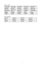
40 drum sounds (see Table 1)
•
4 touch pads
•
12 preset rhythms (see Table 2)
•
4 user rhythms (non-volatile)
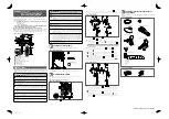
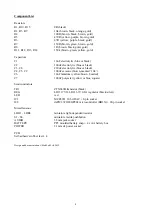
Construction
First fit and solder the resistors (R1 to R15) and trim their legs. Identify the resistors by the coloured stripes
on the body.
Next fit the chip sockets (IC1 and IC2) matching the notch in the socket against the notch in the symbol on
the board. Care should be taken when soldering these components to avoid solder bridges between the pins.
It is not recommended that the chips are soldered directly to the board.
Fit and solder the capacitors, paying attention to the polarity of the electrolytics (C1, C2, C3 and C8)
(negative is marked by a stripe on the side of the body). The tantalum capacitor (C6) should be fitted such
that the shorter leg is by the minus sign. The ceramic capacitors (C4, C5 and C9) and the polyester capacitor
(C7) can be fitted either way around.
Bend the legs of the regulator (REG) at right angles and solder it such that the metal heatsink is flat on the
board and the side with the writing is facing upwards. Solder the LED matching the shorter leg (also flat on
the rim) to the hole with the line.
Solder the pushbuttons (S1 to S6).
Solder the light-dependent resistors (LDR1 to LDR4). Be careful with these components as excessive heat
can melt the plastic.
Solder the transistor (TR1) matching the shape to the symbol on the board.
Solder the jack socket (AUDIO), first cutting off the five small plastic lugs on the underside so it fits flush on
the board.
Solder the power socket (POWER). Optionally also fit the PP3 battery snap (BATTERY). Support holes are
drilled on the board for the battery snap leads. Feed the leads up through the support holes from the track
side of the board and then down the solder holes. Red is positive and black is negative.
Don't fit the chips into their sockets until you have thoroughly checked your construction. Check that all the
components have been inserted correctly and that there are no dry joints and no solder bridges between pins.
Then match the small notch in each chip to the notch in its socket.
Attach rubber feet to the corners of the board.
Either connect a mains power supply (5-9V regulated dc, 300mA, ) to the power socket, or 4 AA
cells to the battery snap.
The software includes a power-on self-test. The LED should flash twice if the board is functioning correctly.
Connect headphones or powered speakers (with a 3.5mm jack plug) to the audio output socket.
Tap the touch pads (LDRs) and you should hear different drum sounds.
1