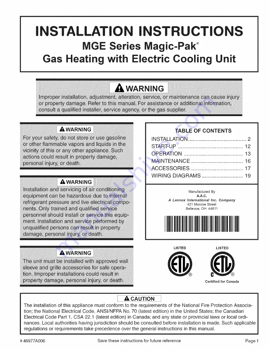
background image

Summary of Contents for MGE10-12

Page 1: ...tallation of this appliance must conform to the requirements of the National Fire Protection Associa tion the National Electrical Code ANSl NFPA No 70 latest edition in the United States the Canadian...

Page 2: ...all national and local safety codes Limitations of the unit and appro priate accessories must also be observed The outdoor fan is designed to operate against no more than 10 W C static pressure Minimu...

Page 3: ...unit Top View Side View Mir Min Front of Unit Minimum clearance to combustibles for the front of the unit is 1 Added clear ance must be provided for the gas supply line and drain trap installation Wa...

Page 4: ...rees landscape materials or building structure Unit can be installed recessed with appropriate wall sleeve accesso ries There is no minimum clearance required on locating the unit to an interior corne...

Page 5: ...operation could result in carbon monox ide poisoning or death The following steps shall be followed for each appli ance connected to the venting system being placed into operation while all other app...

Page 6: ...tall the 5 16 screw that was removed in Step 3 Thread the screw first through the clearance hole in the mounting bracket the proper clearance hole in the vent extension and into the engagement hole in...

Page 7: ...dge of the wall sleeve side Position the bracket so it can be bent around the front corner of the unit Remove one of the two screws in that position on the unit Line up one of the holes in the install...

Page 8: ...containing the unit Blower Performance 1i Low Medium Low MGE10 12 Medium High High MGE10 24 MGE12 18 Low Medium Low Medium High High 52O 685 755 815 65O 945 1010 1090 495 655 715 77O 630 900 960 1030...

Page 9: ...in line should pitch gradually downward at least 1 per 10 of horizontal run to open drain Condensate Drain Installation Figure 7 Electrical Connections All wiring must be done in accordance with the N...

Page 10: ...ontrols as is possible to facilitate removal of controls and manifold Provide a drip leg on the outside of the furnace A manual shutoff valve shall be installed in the gas line outside the unit 5 abov...

Page 11: ...rleakdetection arecorrosive tocertainmetals Carefully rinsepiping thoroughly afterleakdetection has been completed Thermostat The room thermostat should be located on an inside wall where it will not...

Page 12: ...lectrical power to unit 2 Turn the thermostat to lowest setting 3 Turn the gas valve knob to the ON position see Figure 9 4 Turn on electrical power to the unit 5 Set the room thermostat to the desire...

Page 13: ...l power supply and the gas supply to the unit Adjustments Heating Section Temperature Rise At time of installation the temperature rise must be adjusted to be within the range specified on the unit ra...

Page 14: ...set to AUTO the air handling blower will cycle corresponding with the thermostat cycling Suction Superheat MGE10 12 18 20 F MGE10_18 MGE10 24 18 20 F MGE10 30 16_ _180F MGE12 18 10 12 F i MGE12_24 12...

Page 15: ...owing precautions are designed to prevent possible vent system ice blockage that could result in safety shutdown of the burners Adjust to the highest achievable temperature rise within the rise and st...

Page 16: ...nscrewing When replacing the burner tray assembly take care in installing the sense and spark rods back into the burner plate Reconnect the spark and sense wires Heat Exchanger The heat exchanger shou...

Page 17: ...xtruded Aluminum Louver Kit 50 Height MGE10 12 18 24 30 MGE12 18 24 ALVRAL_6 ExtrUded Aluminum Louver Kit 50 Height ASLEEVE2 1 2 Wall Sleeve Kit MGE10 12 18 24 30 MGE12 18 24 Ii I ASLEEVE2 2 2 Wa S ee...

Page 18: ...LEEVE8 3 ASLEEVE8 4 45 45 1 8 29 1 8 ASLEEVEi 0 1 10 I 29 I 29 1 8 29 1 8 ASLEEVE10_2 10 32 W4 32 7 8 29 1 8 ASLEEVE10 3 ASLEEVE10 4 I ASLEEVE12 1 12 29 29 1 8 29 1 8 ASLEEVE12 2 12 32 3 4 32 7 8 29 1...

Page 19: ...AIN FLAME 3 FLASH PRESSURE SWITCH OPEN OR CLOSED BLK BLK RED RED RED GREEN WHITE I I I BLUE I I CMB BLK RGWCY UNUSED ELECTRODE _ BLU ORANG E ORANGE BLK BLK 4 4 RED SEE CHART FOR WIRING 4 FLASH HIGH LI...

Page 20: ...UNUSED _COMPRESSOR CONTACTOR oo_o_s_o_o_ _ 240 208 COM TRANSFORMER Is RKI FLAME 24VAC O_v_f_ _ II 24V PROBE GRD BLOWER IGNITION CONTROL C Y W G R _G AUTO RESET MANUAL RESET LIMIT SWITCH LIMIT SWITCH...

Reviews: