
Check that equipment complies with all applicable building codes, laws, and regulations for its intended use prior to installation.
508196-01
Issue 2120
Page 1 of 18
Manufactured By
Allied Air Enterprises LLC
A Lennox International Inc. Company
215 Metropolitan Drive
West Columbia, SC 29170
Table of Contents
Installation ...................................................................1
Operation ...................................................................11
Maintenance ..............................................................12
Accessories ...............................................................13
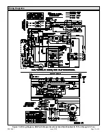
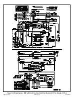
Wiring Diagrams ........................................................15
The installation of this appliance must conform to the requirements of the National Fire Protection Association; the National
Electrical Code, ANSI/NFPA No. 70 (latest edition) in the United States; the Canadian Electrical Code Part 1, CSA 22.2
(latest edition) in Canada; and any state or provincial laws or local ordinances. Local authorities having jurisdiction should
be consulted before installation is made. Such applicable regulations or requirements take precedence over the general
instructions in this manual.
CAUTION
(P) 508196-01
*P508196-01*
Installation
These units are not approved for mobile home
applications. Such use could result in property damage,
personal injury, or death.
WARNING
General
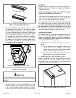
These instructions explain the recommended method of
installation of the MagicPak All-In-One™ HVAC system
model MHP4 electric cooling unit and associated electrical
wiring.
These instructions, and any instructions packaged with
mating components and/or accessories, should be carefully
read prior to beginning installation. Note particularly any
CAUTIONS
or
WARNINGS
in these instructions and all
labels on the units.
Save these instructions for future reference
INSTALLATION AND MAINTENANCE INSTRUCTIONS
MHP4-12/14 Series
Heat Pump / Electric Heat Packaged Unit
This is a safety alert symbol and should never be ignored. When you see this symbol on labels or in manuals, be alert to
the potential for personal injury or death.
Improper installation, adjustment, alteration, service
or maintenance can cause property damage, personal
injury or loss of life. Installation and service must be
performed by a licensed professional installer (or
equivalent), service agency or the gas supplier.
WARNING


