background image


EB3600-P 

User Manual 

PCIe to PCIe Expansion 


MODEL                     

EB3600-P 


Summary of Contents for ExpressBox EB3600-P

Page 1: ...EB3600 P User Manual PCIe to PCIe Expansion MODEL EB3600 P...

Page 2: ...ew 15 Open Enclosure 16 Expansion Interface card Installation 16 Host Interface Card Installation 19 Host Card installation in a Slot Carrier housing 21 Cable Installation 22 Connect cables to expansi...

Page 3: ...tion 42 Windows 42 Linux 43 Chapter 3 Advanced Technical Information 49 EB3600 P Chassis Layout 49 Backplane and LEDs 50 Card Slot Link LEDs 51 Interface Card and LEDs 52 Reset Power Status LEDs 53 Di...

Page 4: ...to configure your network setting in Linux Ubuntu 73 Launch Internet Browser 74 Authentication Log in 74 Default Home Webpage 75 Management Console Web page 75 HOME 75 ADMINISTRATOR 76 SNMP SETTINGS 7...

Page 5: ...ck STEP 5 93 Attach Chassis to Slide Rail Rack STEP 6 94 Secure the Chassis to the Rack STEP 7 96 Earth Leakage Current 96 Grounding the EB3600 P Expansion Chassis 96 Regulatory Safety Requirements 97...

Page 6: ...help you CAUTION Used to indicate and prevent the following procedure or step from causing damage to the equipment WARNING Used to indicate and prevent the following step from causing injury DANGER o...

Page 7: ...Before taking covers off a computer perform the following steps 2 Turn off the computer and any peripheral devices 3 Disconnect the computer and peripheral power cords from their AC outlets or inlets...

Page 8: ...can include wrist straps and smocks when servicing equipment You can also take the following steps to prevent damage from electrostatic discharge ESD When unpacking a static sensitive component from...

Page 9: ...configurations FEATURES Dedicated connectivity for up to four independent hosts Passive host interface no PCIe switch on host link cards provides lowest latency possible Two 1200W 1500W hot swappable...

Page 10: ...all peripherals and host link ENCLOSURE Material Steel Chassis Dimension 16 8 Wide by 7 High 4U by 22 125 Deep 50lbs 2 7kg HOST CONNECTION Host side Any PCIe based host equipped computer preferably G...

Page 11: ...cessary tools required for installation Read this manual Parts List Item Description EB3600 P P Quantity 1 Host Interface card 4 2 1 meter High Speed HD IO cable 16 3 U S Standard 115V Power Cord 2 4...

Page 12: ...b Speed Toggle switches c Two Cable ports one for x8 and the other is x16 3 Power Supply redundant and replaceable a Power cord socket b LED status indicator c Locking Thumb screw d 18 6 2 pin PCIe co...

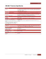
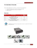
Page 13: ...Magma EB3600 P Chapter 1 Introduction 13...

Page 14: ...Inventory the shipping carton contents for all of the required parts b Gather all of the necessary tools required for installation c Read this manual Tools Required for Installation To complete the in...

Page 15: ...ure cover Turning the system power off at the power on off switch does not remove power to components High voltage is still present CAUTION Before touching anything inside the enclosure move to an ESD...

Page 16: ...m more easily and efficiently If everything works well and there are no configuration issues you can proceed with the installation of the remaining 3rd party PCIe cards Always refer to or read 3rd par...

Page 17: ...fault the Expansion Interface card is set to ON EXP and configured as x16 User should not alter or change the settings of SW3 If you encounter problems for troubleshooting purposes only check SW3 veri...

Page 18: ...Magma EB3600 P Chapter 2 Hardware Installation 18 Backplane with Expansion Interface cards installed see picture below...

Page 19: ...from the AC outlet remove the cover and prepare your host card for insertion into a PCIe slot When the Magma interface card is used as Host interface i e installed in the host computer the RED switch...

Page 20: ...st computer dictates what link width and speed the expansion system will operate in IMPORTANT There is no need to change the dip switch setting when plugging in the Host Interface card into x4 or x8 P...

Page 21: ...allation 21 Host Card installation in a Slot Carrier housing You have to remove the slot carrier housing from the host server in order to install the interface card Remove slot carrier housing Install...

Page 22: ...st modularity between systems and subsystem The cable is available in 1 meter length Connect Cables to Expansion Interface cards and connect the other end to Host Interface cards Be attentive which po...

Page 23: ...ct the second set of cable to the expansion card installed in SLOT 5 of the expansion unit Connect the 1st cable to port X8 A Connect the 2nd cable to port X16 B Connect the third set of cable to expa...

Page 24: ...o port X8 A of the host interface card 2 Take the other end of the 2nd cable and connect that to port X16 B of the host interface card For the 2nd 3rd and 4th set of cables 1 Follow the above methods...

Page 25: ...00 P Chapter 2 Hardware Installation 25 Cable Configurations The picture below shows the correct wrong ways to connect the cables to interface cards host and expansion Correct A to A B to B Wrong A to...

Page 26: ...Magma EB3600 P Chapter 2 Hardware Installation 26 Configuration for EB3600 P Two Host computers attached Four Host computers attached...

Page 27: ...hem in the enclosure with their retaining screws Connect Auxiliary power to PCIe card if required A high power PCIe card such as a GPU requires additional power Aside from the power being supplied by...

Page 28: ...or and sees a mismatch on PCI address space and host system memory capacity Check with GPU manufacturers for details on memory and systems requirements NOTE Increasing the size of the memory may not b...

Page 29: ...can be used as 6 pin or 8 pin connector depending on what the PCI E card or GPU required K80 Installation 1 Connect breakout auxiliary power adapter to K80 power connector 2 Remove slot fillers 3 Alig...

Page 30: ...2 Hardware Installation 30 Remove slot fillers Align K80 on top of the PCIe slot and slowly push it down until firmly seated and secure it Connect the auxiliary power connector to the K80 breakout au...

Page 31: ...oublewide GPUs across the two backplane or how to populate all PCIE slots with series of doublewide GPUs see pictures below When installing a doublewide GPU start with the PCIe slot from the far end l...

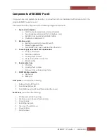
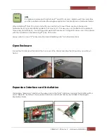
Page 32: ...Magma EB3600 P Chapter 2 Hardware Installation 32...

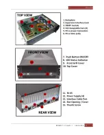
Page 33: ...Magma EB3600 P Chapter 2 Hardware Installation 33...

Page 34: ...our Power Cords for EB3600 P P A single expansion backplane has two power supply modules that require 2 power cords Connecting to Electrical Outlets Connect power cords to electrical outlets When usin...

Page 35: ...nything that uses the same amount of watts that your circuit can handle for example if you have a 120 volt outlet on a 15 amp circuit the max for that outlet is 1800 thus you need to stay WELL UNDER t...

Page 36: ...to 110v 120V and 220V 230V The image below is just an example Electrical outlets vary from country to country Do not use multiple electrical outlets on one circuit line This applies to 110v 120V and...

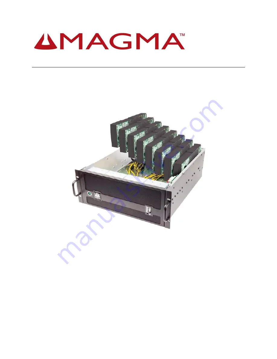
Page 37: ...Magma EB3600 P Chapter 2 Hardware Installation 37...

Page 38: ...ed on both backplanes when the power cable is connected see picture below This signifies the unit is on standby mode Power on EB3600 P Press the Power Button on the front switch to power up the EB3600...

Page 39: ...turn AMBER when the power cord is connected to the device from the outlet When the front button On Off switch is activated or pressed the AC POWER LED should turn green see picture below Power on Comp...

Page 40: ...face cards LED STATUS COLOR D4 D3 D8 and D8 ON Solid Green D5 OFF None Check Expansion and Host Cards LEDs The picture below shows the number of Solid Green LEDS that are illuminated on the Expansion...

Page 41: ...lane LEDs 15 Solid Green LEDs on each backplane are illuminated when the system is turned on LED STATUS COLOR D14 D12 D10 D8 D6 D4 D2 D42 ON Solid Green D1 D3 D5 D7 D9 D11 D13 ON Solid Green D33 D39 D...

Page 42: ...y click on the View Menu and select View Devices by Connection PCI Express Root Port with a PCI Standard PCI to PCI Bridge beneath it The Device Manager will display the available slots within the cha...

Page 43: ...system Typical output from lspci vvv is verbose but you can dig through the information to find very important information There are so many registers and settings associated with PCI Express Switches...

Page 44: ...f 00 Normal decode Flags bus master fast devsel latency 0 Bus primary 02 secondary 03 subordinate 03 sec latency 0 Capabilities 40 Power Management version 3 Capabilities 48 MSI Enable Count 1 8 Maska...

Page 45: ...ilities 138 Power Budgeting Capabilities 10c 19 Capabilities 148 Virtual Channel Capabilities e00 12 Capabilities f24 Access Control Services Capabilities b70 Vendor Specific Information ID 0001 Rev 0...

Page 46: ...ffffff Capabilities 40 Power Management version 3 Capabilities 48 MSI Enable Count 1 8 Maskable 64bit Capabilities 68 Express Upstream Port MSI 00 Capabilities a4 Subsystem PLX Technology Inc Device 8...

Page 47: ...10 Kernel driver in use pcieport Kernel modules shpchp 0b 10 0 PCI bridge PLX Technology Inc Device 8796 rev a prog if 00 Normal decode Flags bus master fast devsel latency 0 Bus primary 0b secondary...

Page 48: ...isabled size 512K Capabilities 60 Power Management version 3 Capabilities 68 MSI Enable Count 1 1 Maskable 64bit Capabilities 78 Express Endpoint MSI 00 Capabilities b4 Vendor Specific Information Len...

Page 49: ...Magma EB3600 P Chapter 3 Advanced Technical Information 49 Chapter 3 Advanced Technical Information EB3600 P Chassis Layout...

Page 50: ...Debug N A N A PORT4 D10 Slot 5 Link Solid Gen 3 Link Fast Blinking Gen 2 Link Slow Blinking Gen 1 Link OFF not Linked PORT 12 D12 Slot 4 Link Solid Gen 3 Link Fast Blinking Gen 2 Link Slow Blinking G...

Page 51: ...g Power Solid power rail OK OFF power rail out of range Card Slot Link LEDs SLOT LED Description When Lit Solid Green or blinking When Off Slot 0 PORT 0 D9 Slot 0 Link Solid Gen 3 Link Fast Blinking G...

Page 52: ...t Power Status LEDs 4 Rx Hint and Tx presets 5 Cable ports x8 A and x16 B 6 SW4 toggle switch for interface mode setting host or expansion 7 Heatsink During normal operation LEDs D7 D8 and D3 should b...

Page 53: ...Ie clock present Lights up if a PCIe clock has been detected No clock present Clock is present D3 3 3V good When on means that the locally generated 3 3V is good and within specification When off mean...

Page 54: ...ternate display will be activated 2 Phase equalization mode D400 will not be lit D401 Phase equalization complete D402 Phase 3 successful D403 Phase 2 successful D404 Phase 1 successful For any link b...

Page 55: ...h the chassis we included below explanations as to what all these items are and how they should be treated Under normal operating conditions the status indicator LED s should be green at all times An...

Page 56: ...ponent you have to reset the SNMP to factory default settings Hold the Alarm Reset button see picture below until the LEDs blink The color of the entire LEDs will turn orange and the device will reboo...

Page 57: ...t below for their corresponding combination of dip switch settings SW3 Link width can be changed by using the following dip switch settings By default the card is set to x16 SW4 Toggle switch for inte...

Page 58: ...CFM RPM and replaceable fans The picture below is the top view of the EB3600 Punit viewing from the back end showing the order of fans starting from left to right Each fan is labeled with a number th...

Page 59: ...nning and restore the chassis lid Fan Specs 92mm X 92mm X 38mm FAN 175 CFM ITEM DESCRIPTION Rated Voltage 12 VDC Operation Voltage 7 0 13 2 VDC Input Current 3 10 3 72 max A Input Power 37 20 44 64 ma...

Page 60: ...as the fan power supply and temperature and PCIe slots via the SNMP Web Management The netburner is programmed with custom SNMP Web GUI for managing and monitoring devices NetBurner Module Replacing...

Page 61: ...acing both index fingers underneath the side of the card and both thumbs on the topside of the card see pictures below 4 Use firm upward pressure underneath the card and a gentle rocking motion until...

Page 62: ...of the NetBurner module and slowly press it down until the board is firmly seated 3 Reconnect the Ethernet cable to the RJ45 port Replacing the Interface Board 1 Disconnect all the wires including the...

Page 63: ...e board NetBurner Interface Board Installation To install the new Interface board just follow the previous steps in reverse order 1 Place the board in the chassis and align it on top of the 4 mounting...

Page 64: ...perations Should one module fail for any reason the power load will be shifted to the other module An indicator for the failure would be the LEDs on the back panel of the power supply behind the chass...

Page 65: ...to its default settings You can only do this once the chassis is turned off but is still operating in standby power So ensure the power cable is connected between the chassis and the AC outlet Each p...

Page 66: ...hapter 3 Advanced Technical Information 66 How to Add Power Module to EB3600 Steps on how to add two additional power supply modules to EB3600 10 unit This applies to EB3600 10 unit that has two power...

Page 67: ...38mm high reliable Sanyo Denki fan is installed to the power supply module for cooling the power supply module power devices on the distribution backplane and part of the system AC Input Table 1 list...

Page 68: ...a The remote sensing is provided to 12V 5V and 3 3V outputs to compensate for excessive cable drops b 5V 3 3V and 12V outputs are located on the power distribution backplane DC Output Load Distributio...

Page 69: ...to the unit No load Operation No damage or hazardous condition will occur with all the DC output connectors disconnected from the load The power supply may latch into the shutdown state Isolation Pri...

Page 70: ...ions to which a power supply may be subjected during operation or shipment Temperature Operating 10oC to 50oC Non operating 40oC to 85oC Humidity Operating 10 to 90 relative humidity non condensing No...

Page 71: ...er supply 2 status Power supply 3 status Power supply 4 status Traps are defined to alert the SNMP server in case of overheating or failure in any of the subsystems mentioned above Remote chassis turn...

Page 72: ...sure to use a Hub with a regular network cable or a crossover cable without a Hub Configure Network Setting Configure your computer s network setting to correlate to the default IP address of the Mag...

Page 73: ...ager by typing service NetworkManager stop command in the terminal 3 Type sudo ifconfig eth0 192 168 1 40 netmask 255 255 255 0 see screenshot below 4 Type route add default gw 192 168 1 1 5 Then pres...

Page 74: ...u type xdg open http 192 168 1 10 on the terminal window see screenshot below If you are getting an error or unable to start the Express IO Manager check your Ethernet cable connection Make sure the E...

Page 75: ...for the expansion device See screenshot below as the default home webpage Management Console Web page HOME The HOME page provides an overview for the status of the chassis It allows you to view the nu...

Page 76: ...d users click on the check box and then enter their name under Enable Disable Users You would then configure their setting based on login information and remote monitoring The configuration is display...

Page 77: ...larm whenever there is a malfunction with the equipment pertaining to the interior of the chassis This feature is shown on Alarm Settings These settings are recommended to stay at its default conditio...

Page 78: ...ure the conditions of the internal fans power supplies or electrical components on the PCIe backplane are functional by following Chapter 3 Advanced Technical Information To verify what is causing the...

Page 79: ...t the expansion unit from the Host computer D Turn ON the expansion unit E Press the front Button a k a Power On Button Front LED ten times continuously F The expansion unit will shut down and reboot...

Page 80: ...ion of that page After you click on the MIB file link save the file as type All Files to your preferred location You may then open the file using Notepad or equivalent text editor and all the informat...

Page 81: ...valent front end SNMP software will display the Magma chassis MIB contents in an explorer like Tree interface A snapshot from the MIB Browser by iReasoning is shown below Under the MIB Tree the Magma...

Page 82: ...version a Right click on the network icon from the system tray b Select Open Network and Sharing Center c Select Local Area Connection d Select Properties e Select Internet Protocol Version 4 TCP IPv4...

Page 83: ...t Button to turn on Audible Alarm C Perform the same methods with the three remaining FANs All Four Fans should be tested Power Supply Test A Disconnect power cord or pull out the power supply from ho...

Page 84: ...Click Sound Audible Alarm alarm should sound off b Click Silence Audible Alarm Express IO Manager Administration Test A Under Enable Disable Users a Enter test in the provided space b Check the box c...

Page 85: ...gh to accommodate the system s depth while providing the proper clearances for air flow and cabling A cabinet with a standard depth of 31 5 inches 800mm should be sufficient however a rack with a non...

Page 86: ...h A 28 00 in Intermediate Length B 25 25 in Forward Extension D min 27 00 in Forward Extension D max 29 00 in Weight Capacity 80 lbs Standard hardware packages include all hardware necessary to mount...

Page 87: ...nit in a rack where the internal rack ambient temperatures will exceed the manufacturer s recommended ambient temperature for all your rack mounted devices 7 Connect all devices installed in a rack ca...

Page 88: ...sed CAUTION Circuit Overloading Consideration should be given to the connection of the equipment to the supply circuit so that overloading of the circuits does not compromise the supply wiring or over...

Page 89: ...portion of the rail completely out until you hear an audible click On the inside of the rail you will see a rail stop hook push the hook up to release and detach the inside portion of the slide comple...

Page 90: ...n 90 Attach Rail to Chassis STEP 2 Attach Slide piece A to the side of the chassis Position the spring end toward the rear of chassis Place as far forward as the whole alignment allows Attach rail sec...

Page 91: ...can be used on any rack slides They do not protrude deep into the chassis but they give enough support Assemble Slide Rails STEP 3 Measure the rack from front to back so you can confirm how long the...

Page 92: ...Magma EB3600 P Chapter 6 Rack Slide Installation 92...

Page 93: ...ers Step 5 between the screws as shown If your rack has holes too large for the screws you can use the Bar Nut to secure your mounting by inserting the Panhead screw through the rack hole and screwing...

Page 94: ...end bracket D Attach Chassis to Slide Rail Rack STEP 6 CAUTION Install the system as low as possible into the rack enclosure For best stability do not install the system above equipment that weighs le...

Page 95: ...es Do this for both sides Next insert the slide rail A inside the grooves on slice part C as shown below Push in until it stops Next press on the safety catch on slide piece A and continue to push unt...

Page 96: ...dard CAUTION The system chassis must be securely grounded to the rack cabinet frame Do not attempt to connect power to the system until grounding cables are connected Completed power and safety ground...

Page 97: ...A r m s is permitted only for PERMANENTLY CONNECTED EQUIPMENT and PLUGGABLE EQUIPMENT TYPE B In also to sell to Denmark the equipment shall be re designed to meet the requirements RESTRICTED ACCESS LO...

Page 98: ...If you are not certain about the power consumption of your peripherals it is best to remove them one by one starting with those you suspect of being most power hungry until the system powers up 3 If...

Page 99: ...elevant to the speed and the amount of data lanes available on the cards Also verify the Magma host interface card is properly inserted into the host computer slot In case any other LED is off ensure...

Page 100: ...tatic wipes 5 Warm water for filter 6 Dish soap for filter Do not use a vacuum because vacuums create ESD First remove the thumbscrews and the top chassis cover Next use a can of compressed air from y...

Page 101: ...ere your Magma Expansion chassis is located To clean this filter follow these simple steps First power down the chassis and then remove the screws on the front panel with a Phillips screwdriver Next o...

Page 102: ...may be used The ExpressBox 3600 supports NVIDIA Tesla GeForce and Quadro GPUs and full access to all GPUs is provided at the rear of the chassis AMD FirePro and Intel Phi co processors are supported 7...

Page 103: ...Power Supply 2 Status Power Supply 3 Status when installed Power Supply 4 Status when installed Traps are defined to alert the SNMP server in case of overheat or failure in any of the subsystems ment...

Page 104: ...possible damage Note Expansion board and PCIe PCI cards that arrive damaged in shipment will not be covered under warranty Returning Merchandise to MAGMA If factory service is required a Service Repre...

Page 105: ...of the FCC Rules Operation is subject to the following two conditions 1 this device may not cause harmful interference and 2 this device must accept any interference received including interference th...

Page 106: ...Manual P N 09 09957 01 Rev A2...

Reviews: