background image

MG10-P1 / MG10-P2

取扱説明書

 / Instruction Manual / Bedienungsanleitung

お買い上げいただき、ありがとうございます。
ご使用の前に、この取扱説明書を必ずお読みください。
ご使用に際しては、この取扱説明書どおりお使いください。
お読みになった後は、後日お役に立つこともございますので、必ず保管してください。

Read all the instructions in the manual carefully before use and strictly follow them.
Keep the manual for future references.

Lesen Sie die ganze Anleitung  vor dem Betrieb aufmerksam durch und folgen Sie beim
Betrieb des Geräts den Anweisungen. Bewahren Sie diese Bedienungsanleitung zum
späteren Nachlesen griffbereit auf.

マルチインターフェースユニット・メインモジュール /

Multi Interface Unit/Main Module / Multi-Schnittstellengerät/Hauptmodul

Summary of Contents for MG10-P1

Page 1: ...rictly follow them Keep the manual for future references Lesen Sie die ganze Anleitung vor dem Betrieb aufmerksam durch und folgen Sie beim Betrieb des Ger ts den Anweisungen Bewahren Sie diese Bedien...

Page 2: ...patibility EMC Part 6 2 Generic standards Immunity for industrial environments For DC power driven products to meet EN 61000 6 2 99 the following operational conditions must be satisfied 1 Input and o...

Page 3: ...J 1 MG10 P1 MG10 P2...

Page 4: ...2 J MG10 P1 MG10 P2 DC AC...

Page 5: ...4 1 23 5 4 2 23 6 26 6 1 RS 232C 27 6 1 1 RS 232C 27 6 1 2 27 6 1 3 28 6 1 4 29 6 1 5 30 6 2 I O 32 6 2 1 I O 32 6 2 2 33 6 2 3 34 1 1 1 1 1 1 2 2 1 3 3 2 4 3 6 3 1 6 3 2 I F 7 3 3 DIN 9 3 4 10 3 5 1...

Page 6: ...MG10 P1 MG10 P2 ii J Microsoft Windows Windows 7 35 8 36 8 1 36 8 2 37 8 3 37 9 38...

Page 7: ...10 P1 MG10 P2 J 1 1 MG10 I F RS 232C I O 1 1 16 I F 1 16 64 1 RS 232C DK DG B DL B BR DT 1 1 DIN 35 mm DIN 1 16 64 DK DG B DL B BR DT 0 1 m 0 5 m 1 m 5 m 10 m P P 4 q w P P 2 RS 232C BCD BCD DC 12 24...

Page 8: ...MG10 P1 MG10 P2 2 J 1 2 MG10 P1 MG10 P2 MG20 DK DK MG20 DG DG B DL B BR MG20 DT DT I F BCD MG30 B1 MG30 B2 RS 232C DZ252 MG10 RS 232C LZ61 CE08 I F...

Page 9: ...MG10 P1 MG10 P2 J 3 1 3 BCD DG DT DL DK PLC 16 RS 232C...

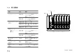
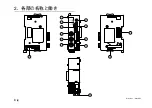
Page 10: ...MG10 P1 MG10 P2 4 J 2 6 7 4 5 8 2 9 10 11 12 13 14 1 3...

Page 11: ...MG10 P1 MG10 P2 J 5 i RS 232C PLC RS 232C DZ252 o LZ61 0 LZ61 1 2 I F I F 3 4 DIN DIN q w e r 0 F t RS 232C RS 232C y I O PLC I O u DC 12 V 24 V...

Page 12: ...MG10 P1 MG10 P2 6 J 3 3 1 16 1 2...

Page 13: ...MG10 P1 MG10 P2 J 7 3 4 2 3 1 1 4 3 2 I F I F 1 1...

Page 14: ...MG10 P1 MG10 P2 8 J 2 I F I F 3 1 3...

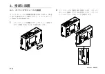
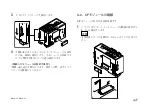
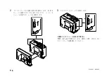
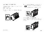
Page 15: ...MG10 P1 MG10 P2 J 9 2 DIN DIN DIN 3 3 DIN DIN DIN 35 mm 1 DIN...

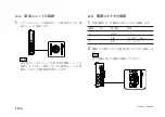
Page 16: ...MG10 P1 MG10 P2 10 J 3 5 1 3 I O 3 GND 2 Vin DC 12 V 24 V 1 FG 2 3 3 4 1...

Page 17: ...MG10 P1 MG10 P2 J 11 3 6 1 LZ61 CE08 RS 232C I F 3 7 1 RS 232C DZ252 RS 232C...

Page 18: ...MG10 P1 MG10 P2 12 J 4 2 5 6 4 2 1 MG10 4 2 2 2 2 4 RS 232C 5 6 4 1 MAX MIN P P Peak to Peak MAX MIN P P P P P P...

Page 19: ...MG10 P1 MG10 P2 J 13 4 2 3 DK 1 1 mm 2 1 mm 3...

Page 20: ...MG10 P1 MG10 P2 14 J 4 2 5 P P 4 RS 232C SETUP P CLOSE 1 mm RS 232C 1 4 2 4 0...

Page 21: ...MG10 P1 MG10 P2 J 15 4 2 6 RS 232C MG30 B BCD 4 RS 232 NG U GO G GO G GO G NG L...

Page 22: ...MG10 P1 MG10 P2 16 J ON P P OFF 4 2 7...

Page 23: ...MG10 P1 MG10 P2 J 17 5 OFF 5 1 RS 232C 5 4 0 1 0 1 4 0 1 4 RS 232C RS 232C 3 6 1 3 RS 232C RS 232C 5 2 9600 bps 8 bit 1 bit CR LF RTS CTS...

Page 24: ...MG10 P1 MG10 P2 18 J 5 2 5 2 1 1 0 F...

Page 25: ...OFF 7 bit ON bit SW 5 1 bit OFF 2 bit ON SW 3 SW 4 OFF OFF OFF ON Even ON OFF ON Odd ON ON SW 2 CR LF OFF CR ON SW 1 OFF ON 5 2 2 RS 232C RS 232C SW1 RS TRG SW 7 SW 8 2400 bps OFF OFF 9600 bps ON OFF...

Page 26: ...J 5 3 2 SW 1 ON OFF SW 2 SW 3 SW 4 OFF OFF OFF DK 0 1 m ON OFF OFF 0 1 m DK 0 5 m OFF ON OFF 0 5 m DG B DT512 ON ON OFF 1 m DT12 DT32 OFF OFF ON 5 m DL BR DL310B DL330B ON OFF ON 10 m OFF ON ON ON ON...

Page 27: ...MG10 P1 MG10 P2 J 21 2 Windows 3 Hypertrm exe 4 MG10 OK 5 Com1 6 Com1 MG10 RTS CTS 5 4 RS 232C RS 232C OFF 6 1 RS 232C 3 Windows 1 MG10 Windows RS 232C DZ252 Com1 Com2 Com1 Com2...

Page 28: ...MG10 P1 MG10 P2 22 J 7 ASCII ASCII ASCII OK 8 R...

Page 29: ...G10 P2 J 23 5 4 2 1 CR CR LF CR Carriage Return LF Line Feed 2 OFF CR LF ON CR e r 0 F q 0 F w 0 F 16 10 0 15 5 4 1 SETUP MODE P CH CL SCN REF LCLR STTERM START RSSEP RS 232C RSFORM RS 232C RSTRG RS 2...

Page 30: ...m 99 9995 99 9995 5 0 3 3 1 m 999 999 999 999 5 m 999 995 999 995 5 0 4 2 10 m 9999 99 9999 99 SETUP SETUP MODE MODE qwMODE e e 0 REAL 1 MAX 2 MIN 3 P P P P P P qwP e e 2 4 0 1 m 99 9999 99 9999 0 5 m...

Page 31: ...S TRG 5 0 s 6 RS TRG 10 s 7 RS TRG 30 s 8 RS TRG 60 s 9 RS TRG 300 s RS TRG CLOSE CLOSE SCN SCN qwSCN e e 1 1 2 2 3 3 4 4 REF REF qwREF e e 0 1 LCLR qwLCLR STTERM STTERM START qSTTERM e e 0 START 1 HO...

Page 32: ...MG10 P1 MG10 P2 26 J 6 RS 232C I O I F I F I F 4 2 3 OFF RS 232C I O...

Page 33: ...1 RS 232C EIA RS 232C 2400 9600 19200 38400 bps 7 bit 8 bit odd even 1 bit 2 bit 15 m RTS CTS RS 232C DZ252 I O 1 N C 2 SG GND 3 I RXD 4 O TXD 5 I CTS 6 O RTS 7 10 V 8 N C SG TXD RXD RTS CTS DSR No 1...

Page 34: ...J 8 1 0 1 m 99 9999 99 9999 2 10 m 9999 99 9999 99 3 F 99 9999 F0 0000 F0 0001 4 Error E r r o r 1 2 CR LF RS 232C 2 CR LF 1 CR 2 OFF CR LF ON CR 0 1 n 6 1 3 5 1 0 F 2 2 0 F 3 3 N A I P P P 4 4 M mm...

Page 35: ...MG10 P1 MG10 P2 J 29 6 1 4 6 1 3 PC PLC LZ61 10 m RS 232C SW1 RS TRG 3 1 2 00 09 9999 2 4 00NM 09 9999 3 5 00NMG 09 9999...

Page 36: ...10 P1 MG10 P2 30 J 1 CR CR LF CR Carriage Return LF Line Feed 2 OFF CR LF ON CR e r 0 F q 0 F w 0 F 16 10 0 15 6 1 5 R r P P P P MAX MIN REAL MODE 5 4 RCL RES START P 5 4 CH 5 4 CL 5 4 SCN 5 4 PAU LCH...

Page 37: ...MG10 P2 J 31 LCH qwLCHe e ON OFF L qwL LO qwLO qwLO e e 99 9999 99 9999 VER qVER qVER e e No 0VER 10 5 4 P P P P qwP P MAX qwMAX MIN qwMIN REAL qwREAL RCL qwRCL RES qwRES START qwSTART P P PAU qwPAUe...

Page 38: ...MG10 P1 MG10 P2 32 J I O 7 P1 COM P2 COM 6 O 5 P1 COM P2 COM 4 I 3 I 2 I RS RS 232C RS 232C 1 I 6 2 I O RS 232C I O 7 6 2 1 I O...

Page 39: ...MG10 P1 MG10 P2 J 33 MG10 P1 COM COM COM OUT COM OUT IN IN 1 2 k 5 V 24 V 5 V 24 V MG10 P1 1 2 W 6 2 2 MG10 P1 MG10 P2 MG10 P2 COM COM COM OUT COM OUT IN IN 5 V 24 V MG10 P2 5 V 24 V 1 2 k 1 2 W...

Page 40: ...MG10 P1 MG10 P2 34 J 6 2 3 RS 232C MIN 25 ms MIN 1 ms RS RS MIN 2 ms MAX 2 ms MIN 2 ms...

Page 41: ...MG10 P1 MG10 P2 J 35 Error 3 5 E 1 00 Error 2 00NM Error 3 00NME Error 2 F 1 00 F0 0000 7 I O RS 232C 6 6...

Page 42: ...W 1 I F RS 232C EIA 232C 2400 9600 19200 38400 bps 7 8 bit 1 2 bit ODD EVEN CR CR LF RTS CTS 16 64 10 m I O P1 COM P2 COM DC5 24 V P1 COM P2 COM DC5 24 V RS MG20 DK MG20 DG MG20 DT 16 1 I F MG30 B1 MG...

Page 43: ...P2 J 37 8 2 I O 7 MC1 5 7 ST 3 5 1 3 MC1 5 3 ST 3 5 1 2 1 1 3 8 3 mm BCD I O 64 5 64 64 5 64 108 5 108 5 33 1 35 65 4 35 23 4 35 20 5 20 5 64 99 105 99 105 99 105 5 64 5 24 5 MG10 P1 MG20 DK MG30 B1...

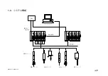
Page 44: ...MG10 P1 MG10 P2 38 J q 12 V 24 V w RS 232C MG10 MG10 e MG10 9 r MG10 t...

Page 45: ...read these Safety Precautions before operating installing maintaining inspecting repairing or otherwise working on this unit Warning Indication Meanings The following indications are used throughout t...

Page 46: ...e actions may also damage the internal circuitry This device operates with DC power supply Absolutely do not connect an AC power supply to the terminals as this may result in fire or electrical shock...

Page 47: ...at 28 6 1 4 Link Connection 29 6 1 5 Operation Commands 30 6 2 I O Connector 32 6 2 1 I O Connector Pin Assignment 32 6 2 2 Input Output Circuits 33 6 2 3 Signal Timing 34 1 Overview 1 1 1 Features 1...

Page 48: ...n the manual Other system names product and service names described in the instruction manual are trademarks or registered trademarks of their corresponding manufacturers 7 Alarm Display Output 35 8 S...

Page 49: ...an electrical parts panel Construction that allows for installation on DIN rails 35 mm DIN rail Expansion from 1 to 16 channels enabled by module configuration Connection of up to 64 channels possibl...

Page 50: ...DK series sold separately MG20 DG For DG B DL B BR series MG20 DT For DT series I F module BCD module MG30 B1 Photocoupler insulated open sold separately collector output current sink type MG30 B2 Pho...

Page 51: ...E 3 MG10 P1 MG10 P2 1 3 System Configuration Computer Measuring unit BCD DG Series DT Series DL Series DK Series PLC Link Max 16 units RS 232C judgment Go No Go...

Page 52: ...4 E MG10 P1 MG10 P2 6 7 4 5 8 2 9 10 11 12 13 14 1 3 2 Name and Function of Each Part...

Page 53: ...This is connected to the I F module 3 Slide locks Secures a module which has been connected 4 DIN rail anchoring lever Secures the main unit to the DIN rails q POWER lamp Lights green when the power i...

Page 54: ...e mixed and used in accordance with the application Up to 16 counter modules can be connected 1 Remove the rubber cover installed over the counter module connector on the right side panel of the main...

Page 55: ...onnector which was installed last When removing the connected counter modules Follow steps 1 to 4 above in reverse Before removing the modules do not forget to release the slide locks 3 2 Connecting t...

Page 56: ...into the main module so that the I F module connectors are aligned properly 3 Secure the I F module using the top and bottom slide locks When removing the connected I F module Follow steps 1 to 3 abov...

Page 57: ...ar panel with the top of the DIN rails 2 Install the unit by pushing it into position until a clicking sound is heard so that the bottom side of the groove in the unit s rear panel fits snugly on the...

Page 58: ...the counter module Connecting the wrong measuring unit can cause a breakdown of the connector 3 5 Connecting the Power Connector 1 Wire the accessory 3 pin connector to the external power supply No I...

Page 59: ...INK IN connector on the main module of the unit to be connected by link connection using the link cable LZ61 If the link cable is not long enough use the CE08 extension cable sold separately to extend...

Page 60: ...ured value value Minimum MIN The minimum measured value value Peak to peak P P The value obtained by subtracting the value minimum value from the maximum value Measuring modes Current value mode maxim...

Page 61: ...ce from the master value preset value to the reference point is calculated and the reference point offset value is generated internally and stored After the reference point has been loaded for the sec...

Page 62: ...ce this value is set the reference point will be set automatically after the power is next turned on when the spindle of the measuring unit is pushed upward by 1 mm or more To set the reference point...

Page 63: ...ent output Measured value upper limit Upper limit NG U Measured value upper limit GO G Lower limit measured value upper limit GO G Measured value lower limit GO G Measured value lower limit Lower limi...

Page 64: ...constantly updated If the maximum value mode minimum value mode or peak to peak value mode is set as the measuring mode the Go No GO judgment output and the output data are not updated even when the...

Page 65: ...mparator set number 1 Comparator upper limit 0 For all set numbers 1 to 4 Comparator lower limit 0 For all set numbers 1 to 4 Start Hold function Start function RS 232C trigger input setting Low speed...

Page 66: ...of the units Unit numbers are used in the commands which are input for the settings and operations Do not set the same unit number among linked units 1 Use a screwdriver or other tool to align the di...

Page 67: ...se parameters are used to set the RS 232C communication specifications Bold print is used to indicate the factory settings When using a link connection be sure to use all the same communication settin...

Page 68: ...tions Do not use the same number for more than one module in the same unit Setting the same number for more than one module will prevent the system from operating properly 5 3 2 Measuring Unit Setting...

Page 69: ...s for RS 232C communication are used when the factory settings are to be changed The new settings will take effect when the setup is ended by the close command The settings established here are stored...

Page 70: ...roperties window and click the ASCII Setup button The ASCII Setup window will appear Check Send line ends with line feeds and Echo typed characters locally and then click the OK button The Properties...

Page 71: ...ameter setup 5 4 2 Details of Command Settings ASCII code is used for all the commands A command is terminated by CR or CR LF CR carriage return LF line feed Select using communication setting switch...

Page 72: ...per limit value or if the upper value is actually smaller than the lower value When changing the setting values be certain after changes have been made that the upper limit value is greater than or eq...

Page 73: ...3 see section 6 1 3 Command Description Write Read RSTRG RSTRG Select the RS 232C trigger or internal timer Command q q q q qRSTRG e e e e e Return format e e e e e 0 RS 232C trigger low speed mode in...

Page 74: ...Reference point function as well All contents other than those set by the setup commands are deleted when the power is turned off Type of operation RS 232C I O connector Measuring mode changes Preset...

Page 75: ...ven selectable Stop bit 1 or 2 bits Cable length Max 15 meters Flow control Hardware flow control RTS CTS Use a DZ252 RS 232C cable sold separately Pin description Pin no I O Description 1 N C 2 SG Si...

Page 76: ...ce Delimiter 2 bytes CR LF or 1 byte CR Select using communication setting switch No 2 on main unit OFF CR LF factory setting ON CR Channel 0 Output data Channel 1 Output data Channel n Output data De...

Page 77: ...e data is output in the specified communication format see section 6 1 3 beginning from the highest order unit regardless of the unit numbers which have been set The highest order unit is the unit con...

Page 78: ...to be set for all units or all modules 6 1 5 Operation Commands List of operation commands Command Setting item Remarks R Load the data of all the channels r Load the data of specific channels P P Sw...

Page 79: ...VER e e e e e e e e e e Version No Starting from the leading byte major version minor version Example 0VER 10 Operation commands For the same commands as the setting commands see the list of operation...

Page 80: ...Pause input While the input signal is supplied the updating of the peak value is temporarily stopped 2 I RS trigger input The data of all the channels at the time when the input signal is supplied is...

Page 81: ...r insulated open collector output current sink type 5 V to 24 V 5 V to 24 V 1 2 W Input circuit Photocoupler insulated input source output supported MG10 P2 COM COM COM OUT COM OUT IN IN External powe...

Page 82: ...f the counter modules used or the RS 232C transmission speed Be sure to input signals after data acquisition is finished MIN 25 ms MIN 1 ms RS trigger input low speed mode RS trigger input high speed...

Page 83: ...al value of the communication data output changes to F Example Mode 1 00 F0 0000 ON OFF Measuring unit is not connected Connection has been cut Measuring unit speed over Count response speed over Over...

Page 84: ...10 to 60 C 20 to 90 RH and humidity range 1 The system cannot be configured in such a way that the total power of the modules connected to the MG10 will exceed 54 W when the supply voltage is 12 V or...

Page 85: ...ne Drawing Units mm 8 2 Accessories 7 pin connector for I O made by Phoenix Contact MC1 5 7 ST 3 5 1 pc installed on main unit 3 pin connector for power supply made by Phoenix Contact MC1 5 3 ST 3 5 1...

Page 86: ...le In the case of link connections are all the MG10 communication settings the same e Problem in the count reading Has the count value overflowed Is the alarm lamp on the MG10 lighted Is the same main...

Page 87: ...n Sicherheitsma nahmen vor der Inbetriebnahme Installation Wartung Inspektion oder Reparatur dieses Ger tes oder der Durchf hrung anderer Arbeiten durch Bedeutung der Warnhinweise Bei der Durchsicht d...

Page 88: ...en auch die internen Stromkreise besch digt werden Dieses Ger t arbeitet mit Gleichstrom Schlie en Sie auf keinen Fall eine Wechselstromquelle an die Klemmen an weil dies zu einem Brand oder elektrisc...

Page 89: ...ikationsformat 29 6 1 4 Link Verbindung 30 6 1 5 Operationsbefehle 31 6 2 E A Anschluss 33 6 2 1 E A Anschlussstiftbelegung 33 6 2 2 Ein Ausgangsschaltungen 34 6 2 3 Signaltaktgebung 35 1 berblick 1 1...

Page 90: ...igen in der Bedienungsanleitung genannten System Produkt und Dienstnamen handelt es sich um Warenzeichen oder eingetragene Warenzeichen ihrer jeweiligen Hersteller 7 Anzeige Ausgabe von Alarm 36 8 Tec...

Page 91: ...eignet sich ideal f r den Einbau in eine Elektroteiletafel Konstruktion gestattet Installation auf DIN Schienen 35 mm DIN Schienen Erweiterung von 1 bis 16 Kan len durch Modulkonfiguration m glich Ans...

Page 92: ...ltlich MG20 DG F r Serien DG B DL B BR MG20 DT F r Serie DT Schnittstellenmodul BCD Modul MG30 B1 Fotokoppler isolierter Open getrennt erh ltlich Collector Ausgang Stromsenkentyp MG30 B2 Fotokoppler...

Page 93: ...G 3 MG10 P1 MG10 P2 1 3 Systemkonfiguration Computer Messtaster BCD Serie DG Serie DT Serie DL Serie DK PLC Link Max 16 Ger te RS 232C Schlecht Beurteilung Gut...

Page 94: ...4 G MG10 P1 MG10 P2 6 7 4 5 8 2 9 10 11 12 13 14 1 3 2 Teilebezeichnungen und Funktionen...

Page 95: ...ihn es u Stromeingang Hier wird die externe Stromversorgung DC 12 V bis 24 V angeschlossen i RS 232C Anschluss Verbindet das Ger t mit einem Computer oder einem PLC Hostger t Der Steckverbinder am End...

Page 96: ...bereinstimmung mit der Anwendung verwendet werden Bis zu 16 Z hlermodule k nnen angeschlossen werden 1 Entfernen Sie die Gummikappe vom Z hlermodul Steckverbinder an der rechten Seitenwand des Hauptmo...

Page 97: ...Zum Entfernen der angeschlossenen Z hlermodule F hren Sie die obigen Schritte 1 bis 4 umgekehrt aus Vergessen Sie nicht die Schiebesperren auszurasten bevor Sie die Module entfernen 3 2 Anschlie en de...

Page 98: ...ittstellenmodul Steckverbinder korrekt ausgerichtet sind 3 Sichern Sie das Schnittstellenmodul mit den Schiebesperren an der Ober und Unterseite Zum Entfernen des angeschlossenen Schnittstellenmoduls...

Page 99: ...die Oberkante der DIN Schiene aus 2 Installieren Sie das Ger t indem Sie es auf die Schiene dr cken bis ein Klicken zu h ren ist so dass die Unterseite der Nut an der R ckwand des Ger tes fest auf der...

Page 100: ...schluss des falschen Messtasters kann ein Ausfall des Anschlusses verursacht werden 3 5 Anschlie en der Stromversorgung 1 Verdrahten Sie den mitgelieferten 3 poligen Stecker mit der externen Stromquel...

Page 101: ...dungskabel LZ61 mit der Buchse LINK IN am Hauptmodul des mittels Link Verbindung anzuschlie enden Ger tes Falls das Verbindungskabel nicht lang genug ist verl ngern Sie es mit dem getrennt erh ltliche...

Page 102: ...genw rtig gemessene Wert Maximalwert MAX Der gemessene Maximalwert Minimalwert MIN Der gemessene Minimalwert Spitze Spitze Wert Der durch Subtrahieren des Minimalwertes vom Maximalwert erhaltene Wert...

Page 103: ...rd die Entfernung vom Hauptwert Voreinstellungswert bis zum Bezugspunkt berechnet und der Bezugspunkt Versatzwert wird intern erzeugt und gespeichert Nach dem zweiten und jedem weiteren Laden des Bezu...

Page 104: ...wird der Bezugspunkt automatisch eingestellt nachdem die Stromversorgung das n chste Mal eingeschaltet oder die Spindel des Messtasters um 1 mm oder mehr hochgedr ckt worden ist Um den Bezugspunkt er...

Page 105: ...swert Beurteilung RS 232C Beurteilungsausgabe Messwert Obergrenze Obergrenze NG U Messwert Obergrenze Gut G Untergrenze Messwert Obergrenze Gut G Messwert Untergrenze Gut G Messwert Untergrenze Unterg...

Page 106: ...ximalwertmodus der Minimalwertmodus oder der Spitze Spitze Wert Modus als Messmodus eingestellt ist erfolgt keineAktualisierung der Gut Schlecht Beurteilungsausgabe und der Ausgabedaten selbst wenn de...

Page 107: ...atznummern von 1 bis 4 Komparator Untergrenze 0 F r alle Satznummern von 1 bis 4 Start Halte Einstellung Startfunktion RS 232C Ausl sereingabe Niedergeschwindigkeitsmodus Einstellung Einstellung Einhe...

Page 108: ...ew nschte Nummer auszurichten Einstellbereich 0 bis F 5 2 2 Kommunikationsparameter Einstellungen Diese Parameter werden zur Einstellung der RS 232C Kommunikationsspezifikationen verwendet Die Werksei...

Page 109: ...FF 19200 bps OFF ON 38400 bps ON ON Datenl ngen Einstellung SW 6 8 bit OFF 7 bit ON Stoppbit Einstellung SW 5 1 bit OFF 2 bit ON Parit tseinstellung SW 3 SW 4 OFF OFF OFF ON Even ON OFF ON Odd ON ON B...

Page 110: ...rden Verwenden Sie nicht dieselbe Nummber f r mehr als ein Modul in einer Einheit Wird dieselbe Nummer f r mehr als ein Modul eingestellt arbeitet das System nicht einwandfrei 5 3 2 Messtaster Einstel...

Page 111: ...en werden Eine Abk rzung wird mit diesem Namen erzeugt 5 Das Fenster Verbindungseinrichtung erscheint W hlen Sie Direkt an Com1 f r Verbindungsmethode in diesem Fenster 5 4 ndern der Werkseinstellunge...

Page 112: ...Fenster Eigenschaften zun chst auf das Register Einstellungen und dann auf die Schaltfl che ASCII Konfiguration Das Fenster ASCII Konfiguration erscheint Aktivieren Sie die Kontrollk stchen Gesendete...

Page 113: ...oder q q q q q Modulnummer 0 bis F oder w w w w w 0 bis F sind Hexadezimalzahlen die im Dezimalsystem 0 bis 15 entsprechen wird verwendet wenn die Einstellungen f r alle Ger te oder Module gelten soll...

Page 114: ...9 bis 9999 99 Befehl Beschreibung Schreiben Lesen CH CH Zum Einstellen der Komparator Obergrenze CL CL Zum Einstellen der Komparator Untergrenze Befehls qw qw qw qw qwCHe e e e e r r r r r Antwortform...

Page 115: ...det Z hlermodus aktiviert LCLR Zum L schen der Bezugspunkt Einstellung Befehlsformat Bezugspunkt Versatzwert qw qw qw qw qwLCLR STTERM STTERM Zur Wahl der externen Starteingabefunktion Befehls q q q q...

Page 116: ...32C Ausl ser nicht benutzt interner Timer 0 5 s 4 RS 232C Ausl ser nicht benutzt interner Timer 1 0 s 5 RS 232C Ausl ser nicht benutzt interner Timer 5 0 s 6 RS 232C Ausl ser nicht benutzt interner Ti...

Page 117: ...zugspunkt Bezug nehmen Beim Ausschalten der Stromversorgung werden alle Inhalte au er den mit den Einrichtungsbefehlen eingestellten Parameter gel scht Operationstyp RS 232C E A Anschluss Messmodus nd...

Page 118: ...Signale Asynchron Start Stopp System Halbduplex System bertragungsrate 2400 9600 19200 38400 bps Daten 7 oder 8 Bit Parit t Keine ungerade oder gerade w hlbar Stoppbit 1 oder 2 Bit Kabell nge Max 15...

Page 119: ...r o r Datenseparateichen 1 Byte Leerstelle oder 2 Byte CR LF Wahl mittels RS 232C Befehl Werkseinstellung Leerstelle Begrenzer 2 Byte CR LF oder 1 Byte CR Wahl mittels Kommunikations Einstellschalter...

Page 120: ...h chstrangigen Ger t ungeachtet der eingestellten Ger tenummern ausgegeben Das h chstrangige Ger t ist das an das Hostger t PC oder PLC angeschlossene Ger t und die untergeordneten Ger te werden ents...

Page 121: ...Einstellen Komparator Satznummer dieser Nummer in Abschnitt 5 4 PAU Zum Aktivieren des Spitzenwert Datenaktualisierungsstopps LCH Zum Aktivieren der Istwert Ausgabedatenspeicherung L Zum Laden des Be...

Page 122: ...Istwert als Maximal und Minimalwert ein Null f r Spitze Spitze Wert und starten Sie die Spitzenwertmessung Befehl Beschreibung PAU Zum Aktivieren des Spitzenwert Befehlsformat Datenaktualisierungsstop...

Page 123: ...gew hlt wird Die Spitzenwertaktualisierung beginnt sobald das Eingangssignal zugef hrt wird Wenn die Speicherfunktion gew hlt wird W hrend das Eingangssignal zugef hrt wird wird der Wert mit dem Istw...

Page 124: ...tokoppler isolierter Open Collector Ausgang Stromsenkentyp 5 V zu 24 V Ger t Eingangsschaltung MG10 P2 COM COM COM OUT COM OUT IN IN Externe Stromversorgung MG10 P2 Angeschlossenes Angeschlossenes Aus...

Page 125: ...RS 232C Kommunikationsgeschwindigkeit verschieden Stellen Sie die Signale nur ein wenn der Erwerb der Daten fertig ist MIN 25 ms MIN 1 ms RS Ausl sereingabe Niedergeschwindigkeitsmodus RS Ausl sereing...

Page 126: ...staster ist nicht angeschlossen Die Verbindung ist unterbrochen worden Messtaster Geschwindigkeits berschreitung berschreitung der Z hlungs Ansprechgeschwindigkeit berlauf Alarmausgabe Alarmausgabe De...

Page 127: ...rtemperatur 10 bis 60 C 20 bis 90 RH und luftfeuchtigkeitsbereich 1 Das System kann nicht so konfiguriert werden dass die Gesamtleistung der an das MG10 angeschlossenen Module 54 W oder 108 W berschre...

Page 128: ...t mm 8 2 Zubeh r 7 poliger Steckverbinder f r E A von Phoenix Contact MC1 5 7 ST 3 5 1 St ck am Hauptger t installiert 3 poliger Steckverbinder f r Stromversorgung von Phoenix Contact MC1 5 3 ST 3 5 1...

Page 129: ...der N he des Kommunikationskabels Sind im Falle von Link Verbindungen alle Kommunikationseinstellungen am MG10 gleich e Falscher Z hlerwert Ist ein Z hlerwert berlauf aufgetreten Leuchtet die Alarmlam...

Page 130: ...ent l usage des acqu reurs de l quipement d crit dans ce manuel Magnescale Co Ltd interdit formellement la copie de quelque partie que ce soit de ce manuel ou son emploi pour tout autre but que des op...

Page 131: ...1 z q w x q w e r t c v b MG10 P1 MG10 P2...

Page 132: ...Suzukawa Isehara shi Kanagawa 259 1146 Japan 1 16 16 For foreign customers Note This product or technology may be restricted by the government in your country Please make sure that end use end user a...

Reviews: