background image

ME-ARC

Advanced Remote Control


Owner’s Manual

(Version


4.0 or higher: with AGS, BMK, ACLD, and PT info)

Summary of Contents for ME-ARC50

Page 1: ...ME ARC Advanced Remote Control Owner s Manual Version 4 0 or higher with AGS BMK ACLD and PT info...

Page 2: ...ealth of the user or other persons may be endangered Copyright Notice Copyright 2010 2014 by Magnum Energy Inc All rights reserved Permission to copy distrib ute and or modify this document is prohibi...

Page 3: ...sible solutions for related issues Product Safety Alerts All electrical work must be performed in accordance with local state and federal electrical codes WARNINGS All electrical work must be performe...

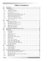
Page 4: ...TECH Button and Menus 36 4 0 Menu Maps ME ARC Remote Control 40 5 0 Operation 45 5 1 Front Panel 45 5 1 1 LED Indicators 45 5 1 2 LCD Display 45 5 1 3 ON OFF Pushbuttons 45 5 1 4 Menu Buttons 46 5 1 5...

Page 5: ...RC 94 9 0 Using an ACLD 95 9 1 Setting Up the ACLD using the ME ARC 95 9 2 Monitoring the ACLD using the ME ARC 95 9 2 1 ME ARC Remote s ACLD METER Button Menus 95 9 2 2 ME ARC Remote s ACLD specific...

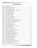
Page 6: ...Figure 3 14 Final Charge Stage Silent 34 Figure 3 15 TECH Button and Menus 36 Figure 3 16 Inverter Fault History Screens 37 Figure 4 1 FAVS CTRL METER Button Menu Maps 40 Figure 4 2 SETUP Button Menu...

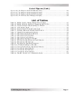
Page 7: ...mote Fault Statuses 83 Table 7 6 AGS Default Settings on ME ARC 84 Table 8 1 BMK Remote Operational and Fault Statuses 93 Table 8 2 BMK Remote SOC Statuses 93 Table 9 1 ACLD Remote Operational Statuse...

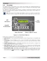
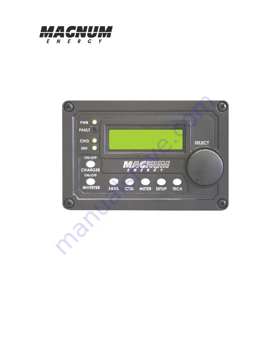
Page 8: ...th the following features LED Indicators The at a glance LEDs provide the inverter charger status in a straightforward way LCD Display The LCD display is a 16 x 2 line 32 characters total alphanumeric...

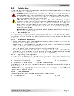
Page 9: ...ARC remote The more thorough you plan in the beginning the better your inverter needs will be met 2 1 1 Installation Guidelines Before connecting any wires determine the remote s cable route throughou...

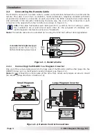
Page 10: ...d around each other for the purposes of canceling out electromagnetic interference known as crosstalk Note The remote cable can be extended up to a length of 200 feet without data degradation 1 2 3 4...

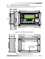
Page 11: ...nd the bezel if applicable Directions for mounting both follow in Section 2 4 5 13 3 cm 3 8 3 cm 5 14 9 cm 3 9 8 cm 9 2 3 cm 1 2 9 cm 1 3 8 cm 1 2 5 cm 2 7 0 cm 1 4 1 cm Figure 2 4 Remote Bezel Dimens...

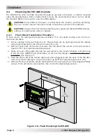
Page 12: ...the re mote and the cable 1 Cut an opening in the wall Figure 2 5 Ensure there are no openings around the display and enough material for the screws to secure the unit 2 Drill four pilot holes for th...

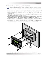
Page 13: ...lace the bezel side with the removed tab over the cable against the wall 4 Position the bezel over the drilled mounting holes and then screw the bezel to the wall using four of the supplied Phillips s...

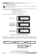
Page 14: ...ENERGY Self Test FAULT PWR CHG INV C 2010 2013 Connecting to FAULT PWR CHG INV ME ARC V 4 0 INV CHG V No LEDs light PWR lights green FAULT lights red CHG lights green INV lights green CHG lights gree...

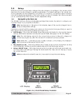
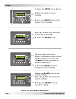
Page 15: ...to find adjust and save the desired settings see Figure 3 1 LCD Display The 2 line LCD display shows status and information for the inverter charger and any attached accessories All setup menus and f...

Page 16: ...SELECT knob to save this setting 3 Press the SELECT knob When the bottom line shows the desired menu heading 1 Press the SETUP menu button Bottom line shows a menu heading 2 Turn the SELECT knob to t...

Page 17: ...n Once you decide which five items you would like to make as your favorites determine the order in which those menus are to appear under the FAVS button This is important since you will assign a FAVS...

Page 18: ...on how to set the battery type FAVS F5 Gen Control This is the F5 default FAVS 5 Refer to the CTRL 03 Gen Control menu on page 72 for information on how to use the Gen Control function Info F5 Gen Con...

Page 19: ...e been programmed in the SETUP menus the features can then be enabled using the CTRL button Example The SETUP 02C AC In Time setting is used to set what time of day e g 12AM to 8AM you want the invert...

Page 20: ...urce is a generator There is no benefit from using the AC In Control feature if the AC source is from a generator the generator power may not be available if an AC In feature is activated Also when th...

Page 21: ...y type CC CV is selected Info When the battery type is CC CV the charger enters Silent mode if Start Float is selected or the charger enters Constant Current charge mode if Hold CV Chg VDC is selected...

Page 22: ...Hz If inverting this meter measures the inverter s output voltage When in Standby mode this meter measures the AC voltage that is passing through the inverter from the source e g grid or generator an...

Page 23: ...Calculated AC1 to Neutral 5A 120V AC2 to Neutral 15A 120V AC1 to AC2 2A 240V 2A 120V 2A 120V Load Amps value add all 120V currents 5A 15A 2A 2A 24A then multiply sum by 120V load 24A x 120V 2880W Whe...

Page 24: ...Inv Chg Amps 10 Amps AC MSH SERIES INVERTER AC Input 10 Amps AC A AC Load 20 Amps AC Inv Chg Amps 10 Amps AC A Inverter Amp meters A A AC CURRENT GRID GEN DC CURRENT BATTERY INVERTER AC LOADS 120ADC...

Page 25: ...starting of another charge mode such as enabling a Start Float charge using CTRL 02 CHG Control Start Float 03C Since EQ Start This meter displays the number of days since the EQ charge mode has been...

Page 26: ...M setting and then press SELECT 01B Screen Setup This setting enables you to adjust the contrast and brightness of the LCD screen and to turn off the Power Save feature or to select the time that dete...

Page 27: ...I use the Link feature By linking you can avoid setting charge parameters that con flict and cause the separate chargers to work against each other Linking allows access to char ger settings in one l...

Page 28: ...12 volt models 23 0 24 4 VDC 24 volt models or 46 0 48 8 VDC 48 volt models In some applications such as those in stalled in an off grid home or when doing a lot of RV dry camping you may want to cycl...

Page 29: ...verter charger automatically con nects and disconnects the incoming utility power based on the inverter s battery voltage Connect Volts This setting determines at what DC voltage the inverter charger...

Page 30: ...voltage Info The transfer to from incoming AC occurs immediately when the Connect SOC or Disconnect SOC setting is reached Info A ME BMK is required in order to use the 02E AC In SOC setting If this...

Page 31: ...e inverter has connected to DC power and is automatically turned on the power button on the inverter or remote can be used to turn the inverter on or off Why use the Power Up Always feature Uninterrup...

Page 32: ...two AC sources and have two inputs AC1 AC2 with the current monitored on each input separately AC1 is set to the size of the utility breaker feeding the AC1 input and the AC2 is set to the size of the...

Page 33: ...e Use the UPS Mode setting when the AC source is well regulated above 105 VAC 200 VAC for export models and the inverter loads are sensitive to voltage fluctua tions This setting is intolerant of volt...

Page 34: ...rge cycles The range of settings are provided to limit the charge current to the battery bank which helps prevent battery overheating caused by charging at too high a charge rate Default 200 ADC Range...

Page 35: ...Time setting The larger the battery bank the longer the time needed to ensure a full charge to the batteries If the setting is from 0 1 to 25 5 hrs the charger transitions to the Silent charge mode a...

Page 36: ...batteries and to run the DC loads This scenario could result in overcharging the batteries since the return amps reading will be skewed by the DC loads Set Max CC CV Time This setting is a safety feat...

Page 37: ...v 24 0 32 0V 24v 48 0 64 0V 48v Float Volts Sets the level at which the charging voltage is held constant during a Float cycle Default 13 2V 12v 26 4V 24v 52 8V 48v Range 12 0 16 0V 12v 24 0 32 0V 24v...

Page 38: ...to revert to the default setting of 2 0 hours Set Absorb Done Amps This setting is used when the DC amperage supplied to the batteries also known as return amps is used to determine when the batterie...

Page 39: ...cted 03E Max Charge Rate This setting is the maximum charge rate allowed to charge the batteries during Bulk Absorption Float and Equalize charging and is provided to limit the charge rate to the batt...

Page 40: ...time accumulated under the METER 03A Charge Time display to determine how long the charger has been in the Bulk Absorption or EQ charge modes Where should I set my Max Charge Time To ensure a complet...

Page 41: ...one Time Amps or SOC CURRENT VOLTAGE TIME Final Charge Stage Float Absorb Volts Float Volts Bulk Charging Absorb Charging Full Charge Float Charging Voltage Current Max Charge Amps ReFloat Volts resta...

Page 42: ...it transitions to Silent Normally the charger enters Silent mode after the Absorption charge mode has finished Once the charger enters the Silent mode the battery voltage is continuously moni tored If...

Page 43: ...etected and 151 C 304 F if a shorted BTS is detected in either situation open or shorted BTS there is no temperature compensation applied to the battery charging voltage PT FETs Displays the temperatu...

Page 44: ...temp at time of fault FETs temp at time of fault Low Battery H1 Charger Stand Low Battery H1 Tfmer 77F Low Battery H1 BTS 78F Low Battery H1 D 0 12 23P Figure 3 16 Inverter Fault History Screens The t...

Page 45: ...If the incorrect PIN number is entered Invalid PIN displays There is no limit on how many attempts can be made to enter the correct PIN number To enter an existing PIN from the Enter SETUP PIN 0 menu...

Page 46: ...play all available screens YES or to just display those screens that pertain to the devices and accessories currently active NO TECH 08 Load Defaults This menu restores factory defaults to all setting...

Page 47: ...n Section 8 2 3 Refer to AGS METER menu maps in Section 7 2 5 02F Input AC2 120 Volts AC P R R R R R R Status Fault 02 AC Meters 02A AC Output 120 VAC 60 0Hz 02C Input Amps 30 Amps AC 02B Load Amps 20...

Page 48: ...nk PT CHG settings YES Set Disconnect Hour 6 00P SETUP button menu map continues on next page Set Search Watts 5 Watts P P P P P P R R R R P P P P P R R R P P P R Range 0 100 R Range 0 100 R Celsius P...

Page 49: ...Amps 30A Set AC2 Input Amps 20A P R R Set AC Input Amps 30A 5A 60A R R R 03A AC Input Amps 30A 03A AC Input Amps 30A 20A P P P 03B VAC Dropout 80 VAC 70 VAC P P P R 60 100 VAC UPS Mode 60 100VAC 60 1...

Page 50: ...2 0 Hrs 03G Final Charge Stage Multi Set Final Charge Stage Multi Set Rebulk Volts 12 0 03E Max Charge Rate 100 Set Absorb Done SOC 100 Refer to AGS SETUP menu maps in Section 7 2 5 Refer to BMK SETUP...

Page 51: ...ections Menu Button Default Current Setting Change Settings Menu Heading Set Search Watts 5 Watts SETUP Press SELECT Rotate SELECT 02A Search Watts 5 Watts Specific fault listed if no fault No Fault H...

Page 52: ...en using the SETUP menu This display automatically powers up with the current system status on the top line and the home screen detailing the inverter s DC voltage and current as shown in Figure 5 1 o...

Page 53: ...rightness and contrast settings under SETUP 01B Screen Setup the CTRL 03 GEN Control setting and the TECH 07 Show All Menus setting which revert back to default The adjustable settings are preserved u...

Page 54: ...duce the overall capacity of the battery To enable the Equalization charge see page 49 WARNING Do not perform an Equalization charge without reading and following all safety precautions pertaining to...

Page 55: ...tatus code that the ARC remote does not identify Remedy Call Technical Support at Magnum Energy 425 353 8833 for assistance in identifying and understanding the actual fault status 5 3 2 Charger Mode...

Page 56: ...hydrogen and oxygen gas To avoid explosions ensure the battery compartment has adequate ventilation in order to dissipate this gas CAUTION Ensure your batteries can be equalized Only do so if permitt...

Page 57: ...external DC source solar wind etc is providing more current than needed which causes the battery voltage to rise The inverter charger reduces the incoming AC current in an effort to keep the battery...

Page 58: ...ge displays when the AC load on the inverter charger s output has exceeded the inverter s AC current protection limits If the overload condition lasts for 10 seconds the fault automatically clears and...

Page 59: ...starts and continues operation As a precaution check the area where the BTS is located if placed on a battery ensure they are not overheated or that the BTS hasn t been placed in a hot area or near a...

Page 60: ...that should be open while inverting is closed Remedy The AC pass thru relay is most likely stuck A relay usually sticks because of damage to the contacts from trying to handle higher currents than th...

Page 61: ...6 2 5 3 4 2 Internal Fault Messages The inverter continually monitors several internal components If a condition inside the inverter occurs that does not allow proper operation one of the following in...

Page 62: ...splay says Full Charge or Silent The charger is in Battery Saver mode This mode monitors the battery voltage level and only charges if the battery voltage decreases to a low level Silent mode will aut...

Page 63: ...made Remote not getting sufficient power from inverter Ensure inverter batteries are connected and the inverter is operating correctly the inverter should be able to invert and power AC loads from th...

Page 64: ...occur only after this mode changes to Bulk charging Absorb charging or Float charging modes Charger not charging even though Charge LED is on steady and the unit says Bulk Charging or Absorb Charging...

Page 65: ...ng based on the ver sion of your ME AGS N this selection or setting may not be available Use Table 7 1 to determine if your ME AGS N is compatible with the selection or setting you want to use Refer t...

Page 66: ...Setting Up the AGS using the ME ARC Press the SETUP button on the ME ARC remote and then rotate the SELECT knob to the 04 AGS Setup display The menus available from this screen allow the generator to...

Page 67: ...oltage is a battery at rest meaning it has no load connected and has been at rest for a minimum of 30 min While this voltage is accurate under these at rest conditions this same voltage with a load ap...

Page 68: ...bsorb charge voltage will decrease In that case the Stop Gen Volts setting should be set well below the Absorb Volts setting 5V below for 12 volt systems A simpler way to charge the batteries to 80 85...

Page 69: ...you are at work each day to have charged batteries when you get home and to avoid having to hear it running SETUP 04C Gen Run Amps Menu This menu autostarts the generator based on the amount of AC am...

Page 70: ...Amps Delay menu Set the Stop Gen AC Amps menu to 20A with a 60 second delay using the Stop Amps Delay menu After 60 seconds of detecting a larger than 25A load on the inverter the generator autostarts...

Page 71: ...Gen Run Temp Menu This menu allows you to automatically start the generator either from an external temperature sensor or by receiving an external input command from an A C thermostat typically to pow...

Page 72: ...ME PT1 requires a 12 volt to common ground input and the ME PT2 requires a two terminal dry contact input Without any connection to an external control circuit the remote temperature sensor cable mus...

Page 73: ...AGS Status menu to identify which condition autostarted the generator This way you will know which auto condition is running longer than the Max Gen Run Time setting Info The Max Gen Run Time menu us...

Page 74: ...ed the Quiet Time Topoff feature will also autostart the generator if the battery s SOC is within 4 or less of reaching the 04D Gen Run SOC start parameter during the topoff time period Where should I...

Page 75: ...long periods of time elapse without using your generator remains connected to external AC power or if you only use your generator a few days out of the year enabling the Gen Exercise feature is recomm...

Page 76: ...Hrs SETUP 04I Gen Warm up Time Menu This menu allows the generator to run i e warm up before it connects to the inverter charger or powers the battery charger and any pass thru loads Most generators n...

Page 77: ...recommend that the batteries be fully charged each time to ensure maximize battery life With this in mind select the amount of days that provides a good balance between reducing fuel consumption and...

Page 78: ...er form the following tests to verify that the AGS system is functioning correctly and there is com munication between the remote inverter and the ME AGS N 7 1 1 1 Remote to Generator Communication Te...

Page 79: ...grid and the other for generator as provided in the MSH4024RE If you are using a MSH4024RE then you can select any AC In selection that is appropriate for your application because the AC In Control fe...

Page 80: ...ring for an autostart condition using active AGS au tostart autostop settings in your ME ARC it must be enabled To enable the AGS 1 Press the remote s CTRL button and then rotate the SELECT knob to th...

Page 81: ...ng read the appropriate related meter for each device Use this menu for AGS verification and testing METER 04C Gen Run Time Menu This read only menu displays the length of time the generator has been...

Page 82: ...E ARC Info When the DIP switch inside the AGS is set to 2 Wire Standby Mode which does not require the gen run sense signal to be present on Terminal 2 of the AGS the Since Gen Run Days timer will not...

Page 83: ...T knob until AGS displays AGS Displays the software version of the AGS connected to the Magnum network displays 0 0 if the remote does not sense an AGS TECH 04 Fault History Press the SELECT knob rota...

Page 84: ...enerator should start Once the generator is running rotate the SELECT knob to AUTO under the 03 Gen Control menu and then press the SELECT knob to select this setting If the generator does not start o...

Page 85: ...No AGS present Start Time Fault Temp Off Start Topoff Quiet Time Start VDC Ready Start 100 SOC Available Statuses P R R P R R R R 04G Hour Meter 00013 Hrs 04F Since 100 13 Days R R Press and hold the...

Page 86: ...Volts OFF Set Start Volts Delay 0 Sec Set Stop Volts Delay 0 Sec Set Start Gen Volts 11 5 Set Start Gen Volts 15 9 Set Start Volts Delay 120 Sec Set Start Volts Delay 127 Min Set Stop Volts Delay 120...

Page 87: ...ax Gen Run Time 25 5 Hrs 04G Quiet Time OFF Set Quiet Time OFF Set Stop Quiet Hour 1 00A Set Quiet Time ON Set Stop Quiet Hour 12 00A Set Stop Quiet Minute 0 45A SETUP Menu continues on next page Set...

Page 88: ...ont Read Only displays TECH 01 Temperatures Press SELECT 01 Temperatures AGS Sensor 82F 02 Versions Press SELECT 02 Versions AGS 0 0 04 Fault History Press SELECT AGS Fault H1 00F Each AGS fault has 3...

Page 89: ...arm up the inverter charger s AC input ignores any incoming AC power This prevents the inverter charger from loading the generator during warm up Once the AGS has determined that the generator is run...

Page 90: ...n the SETUP 04K Gen 100 SOC Start Days setting Table 7 4 AGS Remote Start Statuses 7 2 6 3 AGS Remote Fault Statuses The following Fault statuses indicate that the generator wasn t able to start based...

Page 91: ...tor starts or until all its start attempts are reached which causes the AGS to go into a fault condition indicated by a blink ing FAULT indication on the remote and a solid red STATUS indicator on the...

Page 92: ...age Example 7 3 2 Resolving AGS Operational Statuses The following operational statuses can display on your ME ARC and some may indicate an ab normal condition This section provides additional informa...

Page 93: ...ailed to autostart and run per the SETUP 04D Gen Run SOC menu s start parameters Fault Temp The generator failed to autostart and run per the SETUP 04E Gen Run Temp menu s start parameters Fault Test...

Page 94: ...time when added to your autostop condition does not exceed the SETUP 04F Max Gen Run Time setting Info Beginning with Version 5 2 of the ME AGS N the Max Gen Run Time setting can be defeated In some...

Page 95: ...Out display reads 000 and you begin powering a 25 amp load for two hours the display will show 050 This indicates that you have discharged 50 AH 2 x 25 from the battery If the charge efficiency setti...

Page 96: ...ry bank information It also covers the various LCD displays that are related to the battery monitor and the status of the sense module s LED indicator 8 2 1 How does the BMK Battery Monitor Operate Th...

Page 97: ...dicate that the SOC reference point is being calculated After the batteries are fully charged the display changes from Think n to 100 and begins to provide accurate SOC values Note If the sense module...

Page 98: ...lay press and hold the rotary SELECT knob for three seconds while the Minimum VDC display is shown After this value has been reset the display will begin monitoring and showing new minimum DC input va...

Page 99: ...ory Fault Power up Fault Unknown Fault 05H Minimum VDC 10 6 VDC 05F Reset AH Out 200 0 AH P Read Only displays METER 05A BMK Status BMK Status 05B Battery SOC Think n 05C DC Volts BMK 14 14 VDC 05G To...

Page 100: ...tion cable ensure it is connected correctly If the ME BMK commu nication cable is missing a standard 2 conductor telephone cable may be temporarily substituted Factory Fault The BMK has lost its facto...

Page 101: ...onitor by removing all power from the BMK If the fault remains or returns after resetting the BMK will require repair at a Magnum Energy factory service facility Power up Fault The BMK s power up sequ...

Page 102: ...toring the ACLD using the ME ARC This section covers the menus under the ME ARC s METER button that enable you to monitor the ACLD controller s operation 9 2 1 ME ARC Remote s ACLD METER Button Menus...

Page 103: ...arger Status METER Press button Press SELECT R rotate SELECT knob 06A ACLD Status Status Fault Status Fault 06 ACLD Meters P 9 2 2 ME ARC Remote s ACLD specific TECH Menus Press the ME ARC s TECH butt...

Page 104: ...s in the Absorb stage until the SETUP 03D Absorb Done Time setting has been satisfied then goes into the Standby Float stage Standby Bulk The ACLD is not actively diverting current but the battery vol...

Page 105: ...bove rated current This may be the result of a load that is not sized correctly or may be a bad power board Remedy Ensure that the load is connected Press the ON OFF switch on the side of the ACLD con...

Page 106: ...s but can be adjusted if using the CC CV or Custom selections Default setting Flooded Range AGM1 AGM2 Flooded GEL CC CV Custom Set Battery Type GEL Flooded AGM1 or AGM2 When the battery type selection...

Page 107: ...ps Hold CV Chg VDC Set CV Chg Done Time This setting determines how long the charger holds the bat tery voltage at the CV Charge Volts setting based on a set time period When using time the battery ba...

Page 108: ...a high voltage for an extended time Monitor the batteries to ensure they are not overcharged Info The internal timer for the Set Max CC CV Time feature increments when the battery voltage is above th...

Page 109: ...uring the Equalization charge Note The EQ Volts setting cannot be set lower than the Absorb Volts setting or more than 2 volts 12v systems 4 volts 24v systems or 8 volts 48v systems above the Absorb V...

Page 110: ...bsorb time may be needed in order to obtain the appropriate absorb time for your battery type and battery bank capacity See Table 3 2 to help select the Absorb Done Time setting based on the amp hour...

Page 111: ...tting uses the maximum charging capability of the PT controller to charge the batteries if needed while a 0 setting minimizes the charging current The Max Charge Rate setting is provided as a percenta...

Page 112: ...rovides the option to set the PT controller to start the Bulk charge cycle each new day at sun up Note A new day is defined as for a networked PT after midnight for a standalone PT two hours of no sun...

Page 113: ...g two sides means either side can be open or closed at any time so using the terms open or close doesn t appropriately describe the relay status When describing this relay s contact status or operatio...

Page 114: ...int at which the Alarm OFF Delay time begins Once the battery voltage has reached this setting continuously for the duration of the Alarm OFF Delay setting the alarm will turn off This setting can be...

Page 115: ...stant Voltage modes if battery type CC CV is selected Note When the charge mode begins if the 06A Battery Type selection is CC CV the char ger enters Constant Current mode Charger Off The Charger Off...

Page 116: ...Aux Relay contacts to stay disengaged When the Aux Relay is disengaged the COM to N O contact is open and the COM to N C contact is closed This setting can be used to manually control the device conn...

Page 117: ...ult Mode Messages for a list of PT controller faults Note The Aux Relay automatically disengages when the PT fault is cleared CTRL 04D PT MPPT Ctrl To maximize energy harvest under partially shaded co...

Page 118: ...rging Equalizing Float Charging Sleeping UnknownStatus PT Faults ARC Fault PT BTS Open PT BTS Shorted PT FET Overtemp PT Ground Fault PT HiBatt Temp PT High Bat VDC PT High PV VDC PT Ind Overtemp PT I...

Page 119: ...ut of the PT controller occurring now in Watts Life This display shows the total power out of the controller since it was installed shown in Megawatt hours or MWh To reset this display access the Rese...

Page 120: ...ax Pwr Displays the maximum power output from the PV array in kilowatts shown as KW and the time of day it occurred to nearest 6 minute increment The max range is 25 5 KW 1 KW or 100W resolution METER...

Page 121: ...ault Fourth screen Displays the PT s relay status at the time of this fault Fifth screen Displays the battery s voltage and the battery s amperage at the time of this fault Sixth screen Displays the v...

Page 122: ...et Volts 14 0 VDC 100F 07E Bat Amps PT 100 0 ADC Absorb Charging Float Charging Int Overload PT ARC Fault PT Ground Fault PT Int Phase PT BTS Open PT HiBatt Temp PT Int Power PT BTS Shorted PT High Ba...

Page 123: ...y 002 Max PV 151 VDC 4 38P Day 002 AH to Batt 16400 AH Day 001 Harvest Total 011 3 KWH Day 001 On Work Time 11 6 Hrs Day 001 Max Bat 13 5 VDC 11 22A Day 001 Max PV 136 VDC 10 11A Day 001 AH to Batt 14...

Page 124: ...5 6 P P R R R 12 0 16 6 VDC 12 0 16 6 VDC 12 0 16 6 VDC 0 1 25 5 Hrs R P P Set CV Charge Volts 13 8 P Set CV Chg Done Time P R OFF 20 990 ADC R R Hold CV Chg VDC Amps Set Recharge Volts 12 0 Set CV Ch...

Page 125: ...unUp YES NO P P Set Bulk Start SOC 80 R R OFF 9 0 16 0 OFF 50 99 P 06F PT Aux Relay 10 0 to 14 0 06G PT Alarm 10 0 to 14 0 06H PowerSave PT Display 15 Min P Relay Engage Volts 10 0 R 8 0 16 6 Relay En...

Page 126: ...sun is based on low PV voltage and no effective power i e nighttime UnknownStatus This status message displays when the inverter charger has sent a fault code that cannot be determined by the ME ARC r...

Page 127: ...t Tran sistors have exceeded their safe operating temperature 85 C 185 F HiBatt Temp PT F07 The PT controller turned off because the BTS has reached a very high temperature 55 C 131 F Int Overload PT...

Page 128: ...t Temp P03 Power Limited Internal High Temperature The temperature in side the PT controller is getting high so the output current is being lim ited in an attempt to prevent the controller from shutti...

Page 129: ...e PT owner s manual for more information on the ARC fault test button Info The ARC fault circuit is normally enabled However if an external system ARC fault detection indicator is installed the ARC fa...

Page 130: ...he BTS port for cleanliness and or have the controller serviced Note This fault automatically clears and the unit resumes operation when the BTS temperature has cooled down to 50 C 122 F or below Manu...

Page 131: ...e not in sync with each other Remedy When this fault condition occurs the controller shuts down to help protect itself Press the PT s RESET pushbutton for one second to turn the controller on and to v...

Page 132: ...me or greater than the level required your in verter can support the device setting feature you want 4 If your inverter does not have the required compatibility level for a feature setting you want co...

Page 133: ...Volts AGS 04C Gen Run Time 04D AGS Temp 04E Since GenRun 04F Since 100 Level 1 6 04G Hour Meter Level 1 05 BMK Meters 05A BMK Status Read Only Level 1 6 Read Only 05B Battery SOC 05C DC Volts BMK 05D...

Page 134: ...t Celsius Level 1 Fahren heit 01D Max Charge Amps OFF 20 990 ADC Level 1 200 ADC 01E Link PT CHG settings YES NO Level 1 YES 02 Invert Setup 02A Search Watts OFF 5 50 Watts Level 1 5 Watts 02B LBCO Se...

Page 135: ...5 5 Hrs 12 Hrs Recharge Volts 12 0 16 0 VDC 12 0 V Hold CV Chg VDC 03D Absorb Done Time 0 1 25 5 Hrs Level 4 4 2 0 Hrs Amps 0 250 ADC Level 4 5 20 ADC SOC 50 100 Level 4 5 100 03E Max Charge Rate 10 1...

Page 136: ...s Level 1 OFF Run Hour Min AM PM 12 00A 11 45P Run Time 0 1 25 5 Hrs 1 0 Hrs 04I Gen Warm up Time 0 127 sec 1 127 min Level 1 60 Sec 04J Gen Cooldown Time 0 127 sec 1 127 min Level 1 60 Sec 04K Gen 10...

Page 137: ...2 0 hours 5 Requires Level 4 to display 6 SOC features require the ME BMK Battery Monitor Kit to be installed 7 To manually turn the generator on with the remote a ME AGS N Version 5 0 or higher is r...

Page 138: ...ginal date of purchase by a dated bill of sale itemized receipt 5 The original purchaser shall return the product prepaid to Magnum Energy in Everett WA After the completion of service under this limi...

Page 139: ...Magnum Energy Inc 2211 West Casino Rd Everett WA 98204 Phone 425 353 8833 Fax 425 353 8390 Web http magnumenergy com ME ARC Owner s Manual PN 64 0030 Rev C...

Reviews: