background image

OPERATING MANUAL


MODEL NO.:


MI-16300

 & MI-16303

Summary of Contents for MI-16300

Page 1: ...OPERATING MANUAL MODEL NO MI 16300 MI 16303 ...

Page 2: ... clutter from the machine and the table surface before using the machine Keep hands well away from the belt disc and all moving parts Use a brush not your hands to clear away chips and dust Make sure the sanding belt and disc are correctly and securely installed on the machine Do not operate the sander if the sanding belt or disc is worn or damaged Do not force material against the sander The mach...

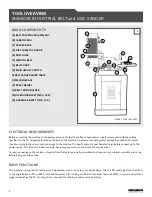
Page 3: ...e with greater voltage than needed can result in serious injury to the user as well as damage to the machine If in doubt contact a qualified electrician before connecting to the power source This tool is for indoor use only Do not expose to rain or use in wet or damp locations For your convenience this sander is shipped from the factory partially assembled and requires only minimal assembly and se...

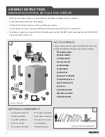
Page 4: ... 17 mm open end wrench 10 mm open end wrench 8 mm open end wrench 2 5 mm Allen key Combination square ASSEMBLY INSTRUCTIONS MAGNUM INDUSTRIAL BELT and DISC SANDER Before you assemble your band saw review the parts breakdown and keep it ready for reference Start by removing the parts from the packaging Carefully check the packaging for small pieces before you continue Lay out the parts on a large c...

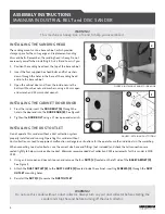
Page 5: ...alled and running Operating this sander without dust collection can lead to equipment malfunction or dangerous situations for the operator or other individuals in the workshop When connecting to a dust collector use the correct size hose and fittings not included and check that all connections are sealed tightly to help minimize airborne dust Minimum recommended dust collection CFM requirements fo...

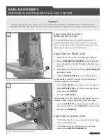
Page 6: ... the table is not at 90 loosen the table LOCK LEVER B and adjust the table 4 Tighten LOCK LEVER B to secure the table in position Once the table is set to 90 check the 90 positive stop To adjust the stop follow these steps 5 Loosen LOCK NUT C using a 8 mm wrench See Figure 7 6 Adjust SET SCREW D using a 2 5 mm Allen key until the screw sits on the STOP E 7 Re tighten LOCK NUT C After the table set...

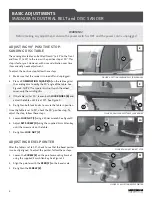
Page 7: ...re 9 4 Re tighten both lock knobs to secure the table in position Once the table is set to 90 check the 90 positive stop To adjust the stop follow these steps 5 Loosen LOCK NUT C using a 10 mm wrench See Figure 10 6 Adjust SET SCREW D using the supplied 3 mm Allen key until the screw rests on the table 7 Re tighten LOCK NUT C ADJUSTING BEVEL POINTER After the table is set to 90 check to see that t...

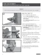
Page 8: ...ND into the sanding head See Figure 13 Note When reinstalling the table thread the SHORT END of the stud into the sanding head 6 Reinstall the TOOTHED NUT D onto the STUD E 7 Slide the BACKSTOP HOLDER J onto the STUD E and secure it by reinstalling and tightening the LOCK LEVER C SPRING B and PAN HEAD SCREW A See Figure 14 8 Loosen and remove the BOLT K and WASHER L from the BACKSTOP M 9 Place the...

Page 9: ...t from vertical to horizontal position follow these steps 1 Make sure the sander is turned off and unplugged 2 Using a 10 mm wrench and the supplied 3 mm Allen key loosen LOCK NUT E and then SET SCREW F 3 Move the sanding head to the horizontal position 4 Retighten SET SCREW F and LOCK NUT E to secure the sanding head in position Note You may need to adjust the sanding belt tracking after changing...

Page 10: ...t this process until the belt tracks evenly REPLACING SANDING BELT To replace the sanding belt first ensure the sander is turned off and unplugged Then follow these steps 1 Loosen and remove the BOLTS C from the UPPER GUARD D Then remove the UPPER GUARD D See Figure 21 2 Loosen and remove the SCREWS E and remove the LOWER GUARD F 3 Push the BELT TENSION LEVER G up to release tension 4 Remove the o...

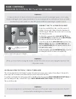
Page 11: ...r to protect the motor from power surges or spikes in line voltage In the event of a power surge the circuit breaker will automatically trip and cut off power to the motor To reset the circuit breaker first set the power switch to the OFF position Then press the CIRCUIT BREAKER RESET BUTTON D If you have wired your sander s motor to 110 V press CIRCUIT BREAKER RESET BUTTON E to reset the breaker T...

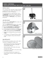
Page 12: ...that matches the radius of the workpiece 2 Using the supplied 3 mm Allen key secure the CENTRE POINT in position by tightening the SET SCREW E 3 Place the centre of the workpiece on the centre point s PIN F 4 Turn the sander on and manually rotate the workpiece against the sanding disc until you achieve the desired results MAINTENANCE Before performing any maintenance make sure the sander is turne...

Page 13: ...ortation costs are not covered by the warranty As determined on a case by case basis parts may need to be inspected by an authorized Magnum Industrial representative before parts are eligible for warranty In these cases the original purchaser is responsible for transporting the parts to a representative or an authorized Magnum Industrial service centre LABOUR AND TRANSPORTATION COSTS The original ...

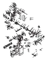
Page 14: ...1 55 125 130 8 58 11 12 78 75 126 100 5 85 3 13 73 46 17 134 14 50 70 76 133 77 22 21 18 79 132 71 80 15 45 43 72 44 20 19 68 16 104 102 7 143 139 156 157 158 31 142 141 174 128 127 161 27 165 118 73 35 80 155 167 154 119 166 138 65 101 66 29 103 63 135 63 30 153 116 28 105 33 151 4 1 152 122 2 60 6 62 59 32 180 179 181 178 175 176 170 73 178 172 73 182 183 184 185 186 115 116 163 162 116 168 169 ...

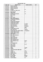
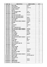
Page 15: ... SHAFT BRACKET 70x26x8 1 MI 16300 22 UPPER WHEEL ADJUSTING SPRING ψ4 5xψ30x60 1 MI 16300 23 LOWER WHEEL GUARD 1 MI 16300 24 LOWER WHEEL ALUM 5 1 MI 16300 25 BELT TABLE 1 MI 16300 26 BELT TABLE BRACKET 1 MI 16300 27 DISC TABLE 1 MI 16300 28 ANGLE SLIDE RH 1 MI 16300 29 ANGLE SLIDE LH 1 MI 16300 30 ANGLE BRACKET RH 1 MI 16300 31 ANGLE BRACKET LH HOLE 1 MI 16300 32 KNOB 7 16 2 MI 16300 33 12 SANDING ...

Page 16: ...3 8 7 MI 16300 74 PHILLIPS HEAD SCREW W WASHER 3 16x3 8 3 MI 16300 75 BEARING 6206 2 MI 16300 76 HEX SCREW 1 4x3 4 2 MI 16300 77 FLAT WASHER 1 4x16x2 2 MI 16300 78 STOP SCREW M5x10 2 MI 16300 79 ADJUSTING PLATE 1 MI 16300 80 PHILLIPS HEAD SCREW W WASHER 3 16x1 4 1 MI 16300 81 HEX NUT M5 2 MI 16300 82 STOP SCREW M5x30 2 MI 16300 83 SPRING PIN 4x12 2 MI 16300 84 HALF CIRCLE KEY 2 MI 16300 85 DOUBLE ...

Page 17: ...2x30 1 MI 16300 132 ADJUSTING SPRING SMALL ψ1xψ8x17L 1 MI 16300 133 WAVE WASHER ψ12 5Xψ17 1 MI 16300 134 BRACKET OF UPPER SHAFT 35x23x10 1 MI 16300 135 STOP SCREW M6x10L 2 MI 16300 137 ARROW LABEL 100x15 1 MI 16300 138 TERMINAL A3 1 1 MI 16300 139 TERMINAL CE 2 4 MI 16300 140 SPRING PIN 6x14 2 MI 16300 141 HEX SCREW 5 16x4 4 MI 16300 142 FLAT WASHER 5 16x15x2T 8 MI 16300 143 HEX NUT 5 16 4 MI 1630...

Page 18: ...00 174 CLOSED STAND 1 MI 16300 175 HEX NUT 3 16 6 MI 16300 176 PHILLIPS HEAD SCREW W WASHER 3 16 x1 4 10 MI 16300 177 SWITCH ASS Y 1 MI 16300 178 DUST CHUTE YW1075 3 MI 16300 179 DUST HOSE 4 x300 MM 1 MI 16300 180 DUST HOSE CLAMP 4 x1 4 2 MI 16300 181 HEX NUT 3 16 4 MI 16300 182 PHILLIPS HEAD SCREW 2 MI 16300 183 HEX NUT 2 MI 16300 184 STOP PLATE 1 MI 16300 185 SWITCH COVER 1 MI 16300 186 ON OFF S...

Reviews: