background image

Mahindra USA, Inc. 

5203  Aeropark Drive   

Houston, TX 77032

(281) 449-7771  

www.mahindrausa.com

Summary of Contents for 10 Series

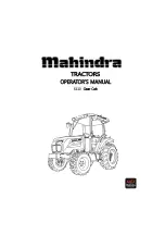
Page 1: ...Mahindra USA Inc 5203 Aeropark Drive Houston TX 77032 281 449 7771 www mahindrausa com...

Page 2: ......

Page 3: ......

Page 4: ......

Page 5: ...tion for a period of five years or 3000 hours of operation whichever occurs first for all engines rated at 19 kW or greater However In the absence of a device to measure hours of use the engine shall...

Page 6: ...red to make the warranty repair This includes diagnosis and labor to remove and install the engine if necessary Owner s Warranty Responsibilities As the Daedong USA INC off road compression ignition e...

Page 7: ...of a lack of performance of required emission control maintenance as outlined in your Owner Manual Parts or accessories used in applications for which they were not designed or not approved for use o...

Page 8: ...for constant speed engines rated under 37 kW with rated speeds greater than or equal to 3 000 rpm the warranty period is 1 500 hours or 2 years of use whichever occurs first after the date of delivery...

Page 9: ...peration and Efficiency of emission control and engine performance depends on adherence to proper operation and maintenance recommendations as well as the use of recommended fuels and lubricating oils...

Page 10: ...ne at any repair facility Such non warranty work need not be performed at a designated warranty station in order for the warranty to remain in force CUSTOMER ASSISTANCE EMISSION CONTROL SYSTEM WARRANT...

Page 11: ...RNIA Proposition 65 Warning The Engine Exhaust from this product contains chemicals known to the state of California to cause cancer birth defects or other reproductive harm WARNING SIGNS IN THIS MANU...

Page 12: ...7 Section B 10 Lubrication maintenance 58 80 Section C 11 CABIN 81 92 Section D 12 Specifications 93 97 13 Fuel Saving Tips 98 99 14 F lt T i 100 103 14 Fault Tracing 100 103 15 Wiring Diagram 104 109...

Page 13: ...NTY OF THE PRODUCT The manufacturer warrants this product and full details of the warranty are provided on a separate Carved position of the chassis number warranty schedule SERVICE Service is availab...

Page 14: ...this manual are carried out at the recommended intervals Read this Manual carefully and keep it in a convenient place for future reference If at any time you require advice concerning your Tractor do...

Page 15: ...latest methods of servicing Tractors They stock genuine spare parts and are backed by the Company s full support Throughout this manual the use of the terms LEFT RIGHT FRONT and REAR must be understoo...

Page 16: ...o charged engines with 4 cylinders of 6110 designed by Daedong Clutch and Transmission A single plate dry clutch 10 83 diameter is used on these tractors Tractors with IPTO Independent Power Take Off...

Page 17: ...Electrical system comprising Horn and Head Lamp The side indicator Lamps Plough Lamp Brake Light Gauge lamp Hazard Lamp Generator or Alternator and Fuse box also from part of the Electrical system Whe...

Page 18: ...r of the Dealership explain the problem and request assistance When additional assistance is needed your Dealer Distributor has direct access to your office If you cannot obtain satisfaction by doing...

Page 19: ...used to enter low buildings etc Take care when lowering the upper section of the ROPS frame and take extreme care while driving the tractor with the ROPS frame lowered Do not wear the seat belt with...

Page 20: ...PS for pulling purposes this will cause the Tractor to tip backwards Always pull from the Tractor drawbar Be careful when driving through door openings or under low overhead objects Make sure there is...

Page 21: ...tion Figure 1 identifies the seat fitted to your Tractor FOR SLIDING SEAT To select Seat position move Adjusting lever and slide Seat closer to or away from Dash panel and g controls Check whether the...

Page 22: ...READ SAFETY INSTRUCTION Carefully read all safety instructions given in this manual for Carefully read all safety instructions given in this manual for your safety Tempering with any of the safety de...

Page 23: ...n during machine operation when the machine is equipped with a certified ROPS Failure to do so will reduce or eliminate protection for the operator in th t f ll the event of a roll over PRECAUTION TO...

Page 24: ...ic roads unless prohibited by state or local regulations Use the slow moving vehicle SMV sign when driving on public roads during both day night time unless prohibited by law PRACTICE SAFE MAINTENANCE...

Page 25: ...oisonous It is strong enough to burn skin cause holes in clothing and cause blindness if it comes in contact with your eyes For adequate safety always q y y 1 Fill batteries in a well ventilated area...

Page 26: ...sion in neutral position foot brake engaged and the PTO lever in disengaged position while attending to the Safety Starter Switch or any other work on Tractor SAFETY STARTER SWITCH 1 A clutch operated...

Page 27: ...thing which will not get entangled in the moving parts of the tractor or machine and protect him or her from the elements When spraying or using chemicals please ensure that clothing and protective eq...

Page 28: ...Where a tractor is started in a confined area ensure that the area is well ventilated as exhaust gases are very harmful and can cause death 6 Do not work under raised implements 7 When changing wheels...

Page 29: ...uring dusty operations which will reduce visibility substantially 9 Never start the tractor unless the transmission is out of gear the operator is in the seat and all round safety has been checked 10...

Page 30: ...ing illegible or damaged safety signs 8 Keep safety signs clean of dirt and grease Servicing the Tractor 1 Keep the tractor in good operating condition for your safety An improperly maintained Tractor...

Page 31: ...e ventilation Exhaust fumes can cause death 8 Do not park the tractor on a steep slope p p p 9 If power steering or Engine ceases to operate stop the tractor immediately 10 Pull only from the swinging...

Page 32: ...ck the rear wheels from the front and rear side 4 To avoid injury always move down the flip part of PTO Do not clean adjust or service PTO driven equipment when the tractor engine is running 5 Make su...

Page 33: ...er when filling the tank DO Attend to minor adjustments and repairs as soon as necessity is apparent DO All h i l b f i h di fill d ddi h DO Allow the engine to cool before removing the radiator fille...

Page 34: ...T Mount or dismount from the right side of the tractor DON T Tamper the hydraulic control levers upper limit stops DON T U th d ft t l l f lifti f i l t DON T Use the draft control lever for lifting...

Page 35: ...as reference data This symbol means ATTENTION YOUR SAFETY IS INVOLVED The message that follows the symbol contains important information about safety Follow recommended precautions and safe operating...

Page 36: ...DECALS ON THE CABIN Part No 1200 910 023 0 Part No 1200 910 003 0 Part No 1200 910 011 0 Part No 1769 910 009 0 Part No 1200 910 019 0 Part No 1200 910 006 0 Part No 1200 910 004 0 32...

Page 37: ...o 1200 910 015 0 Part No 1220 904 122 1 Part No 1200 910 012 0 Part No 1200 910 016 0 Part No 1200 910 016 0 Part No 1200 910 005 0 Part No 1200 910 024 0 Part No 1769 910 009 0 Part No 1200 910 011 0...

Page 38: ...or minimum Setting Engine Hare fast or g coolant temperature Warning maximum setting Fuel level Hazard warning Transmission oil pressure Engine S N l T i l Stop control Neutral Turn signal Lights Fan...

Page 39: ...eatures of your New Tractor Do not start the engine or attempt to drive or operate the Tractor until you are fully accustomed to all the controls It is too late to learn once the Tractor is moving If...

Page 40: ...hen the key is released it will return to the ON position GLOW Glow plugs preheat the combustion chamber HEAD LAMP TURN SIGNAL SWITCH AND HORN HEAD LAMP SWITCH High and low beam are operated on the ma...

Page 41: ...is ON WATER TEMPERATURE GAUGE WATER TEMPERATURE GAUGE Shows the water temperature with the ignition switch ON C is low to normal temperature H is high temperature If the pointer is in the red H segmen...

Page 42: ...go off as soon as the engine starts to run to indicate that the alternator is changing Oil pressure lamp Will go out as soon as the engine starts if the oil pressure is correct If it comes on while th...

Page 43: ...ut will instantly start rotating if the clutch pedal is released or the implements lowered Two switches operate the independent PTO 1 PTO ON OFF SWITCH PTO ON OFF switch is located on the RHS on the s...

Page 44: ...owards the driver increase revolutions Pushing it away from the driver decreases revolutions CLUTCH PEDAL When the clutch pedal is pressed on models with mechanical transmissions drive is disengaged a...

Page 45: ...ys use it on the road or at high speed as using one side only can cause rollovers When servicing the tractor ensure that the adjustment on both sides is the same Right and left brake pedals are provid...

Page 46: ...ling uphill use the clutch instead Always stop the tractor before getting off Caution Main gear lever This lever can be shifted by using the clutch both when the tractor is stationary or mobile It is...

Page 47: ...ying the brakes The torque of wheel axle is extremely high while creep speed is being used Be sure to step down on the clutch pedal completely before applying the brakes or they will not work When sta...

Page 48: ...mportant Use of front wheel drive improves traction performance Do not use front wheel drive at high speed or on the road as premature wear of components will result Important Always use the clutch wh...

Page 49: ...op the engine and remove the key Set the parking brake Caution When leaving the tractor stop the engine and remove the key Set the parking brake OPERATING THE HYDRAULICS The hydraulics are powered wit...

Page 50: ...KNOB FOR THE 3 POINT HITCH This knob controls the downward speed of the Hydraulic s three point linkage and is positioned at the front of the driver s seat To slow the downward speed Turn the knob cl...

Page 51: ...e implement coupler to the tractor hydraulic coupler 4 Pull the implement coupler slightly to make sure couplers are firmly connected Disconnecting 1 Lower the implement first to the ground to release...

Page 52: ...aping under pressure can have enough force to penetrate the skin Hydraulic fluid may also infect a minor cut or opening in the skin If injured by escaping fluid see a doctor at once Serious infection...

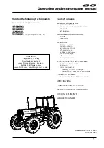
Page 53: ...OPERATING THE 3 POINT LINKAGE TPL 49...

Page 54: ...terconnected ADJUSTMENT OF THE TOP LINK Lengthening or shortening the top link will change the angle of the implement The locating hole of the top link varies with the type of implement used The most...

Page 55: ...EMENT If the PTO is used remove the safety cover off the PTO shaft Adjust the yoke rod on the lower links to suit the implement in use Attach the left lower link then attach the right lower link using...

Page 56: ...nd engine flywheel Only engage the starter for a period of not more than 10 seconds Operators need to wait for glow light to turn off As the lamp goes off turn the key to the start position to start t...

Page 57: ...Important Ensure the handbrake Foot brake is on during the warming period Failure to warm up correctly can result in problems When the engine is warm push down the clutch and engage the main and auxil...

Page 58: ...ght turn use both the steering wheel and the brake pedal at the same time For a left turn use the left pedal and a right turn the right pedal For a left turn use the left pedal and a right turn the ri...

Page 59: ...lock is a very useful feature care should be taken in its use as misuse can lead to dangerous situations The diff lock should only be used in situations where traction is lost on one of the rear wheel...

Page 60: ...warning lamp etc Danger Also check to ensure that the fins in the radiator core are not clogged or that the tractor has a broken or stretched fan belt Allow the engine to cool down before opening the...

Page 61: ...the front track can be set in The rear track can be set in as illustrated TYPE DIVISION TYRE TREAD AG FRONT 9 5 20 Hi Trac Lug 1546 60 9 REAR 14 9 28 Hi Trac Lug 1403 55 2 IND FRONT 10 5 80 18 Contrac...

Page 62: ...Maintenance This section gives full details of the service procedures necessary to maintain your Tractor at peak efficiency while the lubrication and maintenance chart provides a ready reference to t...

Page 63: ...ystem l t l d fill ith th t i t completely and refill with the correct mixture of water and anti freeze or corrosion inhibitor ENGINE OIL Pull out the stick wipe it and dip in the oil sump Ensure that...

Page 64: ...bearing on the life of the tire and its performance in the field Ensure that the tire pressures are correct and in accordance with the table on page 65 It is strongly recommended that tire pressures a...

Page 65: ...essive wear and reduced tractor j performance Caution ELECTRICAL Check the operation of all gauge switches horn lights and indicators INSTALLING LOADER 1 Connect P port of loader control valve to the...

Page 66: ...tick Clean after every Eng Air cleaner 100hrs Replace Element that has Been washed more Than 5 times Radiator coolant Replace every year Check daily top off if required See page 72 R di Check daily fo...

Page 67: ...oth brake pedals Check daily Adjust so that both operate simultaneously and brake at the same time Operatio n of each lever Check daily Smooth operation Free play of steering wheel Check daily About 5...

Page 68: ...dusty conditions Loose bolts and Check daily Tighten to proper t Chassis nuts y torque Check the leakage of oil at the clutch chamber Check once a year with the lower plug pulled out Hydraulic oil fil...

Page 69: ...F SAE20 or 10W30 7 7 2 03 gal Below 0 C 32 F SAE 10W or 10W 30 MAHINDRA HEAVY DUTY SAE 15W 40 3 TRANSMISSION CASE See next page 43 11 36 US gal 4 FRONT AXLE API GL 4 Grades Gear oil 80 or 90 MAHINDRA...

Page 70: ...e Side cover To open grasp the side cover Pull the forward panel upward to separate from guide support pin 1 And pull the side panel forward again FUEL Use clean diesel fuel only As diesel fuel equipm...

Page 71: ...se the fuel injection pump cock 6 The bleeding of the system is now finished e e o e b e o p ge d o e c ge eque cy Changing engine oil Park tractor on level surface shut off engine Remove sump plug dr...

Page 72: ...CHANGING THE TRANSMISSION OIL CHANGING THE TRANSMISSION OIL Remove the drain plug from bottom of the transmission and drain the oil Replace and check the drain plug Refill the transmission to the cor...

Page 73: ...ves and tighten Level gauge Oil Filler Some operators have found that when they fill with the correct amount of oil and check it the oil level on the dipstick is too high due to the fact that it takes...

Page 74: ...in order to remove the fuel filter Attempting to remove the fuel filter with a filter wrench or a filter strap could damage the locking ring 3 Hold fuel filter and rotate quick release collar counter...

Page 75: ...ntacts bare then turn it 2 3rd turn further to tighten it and check for leaks CHANGING THE COOLANT 1 Open the tap in front of the gear pump to drain the coolant 2 Open the radiator cap at the same tim...

Page 76: ...nce with the instructions applicable to the brand of anti freeze and the local climate Replace the solution in the radiator In case of loss of solution due to evaporation or overflow replace with the...

Page 77: ...according to the service schedule page 63 64 and 65 Ensure that grease nipples are cleaned well before any attempt is made to grease them BRAKE AREA CLUTCH AREA PIVOT METAL Grease Nipple Grease Nippl...

Page 78: ...ct ADJUSTING THE BRAKES As is the case with the clutch use of the brakes will change the pedal free play and the balance between the right and left pedal The correct pedal free play is 1 18 1 57 in Th...

Page 79: ...ng wheel and the entire If the toe in adjustment is incorrect it can cause severe shaking of both the steering wheel and the entire tractor The correct toe in is 0 08 0 24in We recommend that this adj...

Page 80: ...emergencies It will partially charge the battery at a high rate and in a short time When using a boost charged battery it is necessary to recharge the battery as early as possible Failure to do this...

Page 81: ...periods Th b tt t f ll h d Fit the gauge 1 at the center of the longest free length and check the tension The correct tension is 535N 120 lb If the tension of the belt is below 250N 56 lb adjust the b...

Page 82: ...sed air Check the element to ensure that it is not damaged Reassemble the element evacuator Never beat the element on a stone or concrete floor wall to clean it Check all connections and hoses especia...

Page 83: ...rs and replace as required Important REPLACING FUSES The circuit has 8 blade type fuses in its wiring circuit See diagram on page 104 105 and 107 When a fuse has blown replace it with one of the same...

Page 84: ...rm storage Drain the oil and replace with new oil R th i f 5 i t th t it h il th h t th i Important Run the engine for approx 5 min to ensure that it has new oil throughout the engine Drain the coolan...

Page 85: ...and air conditioning system It is available in the following version Cab with ventilation and heating systems Cab with ventilation heating and air conditioning systems The cab is in full conformity w...

Page 86: ...ul during implement hitching and unhitching operations When using implement supports be sure they are suitable and sufficiently strong Doors h d id d i h k l k INSTRUMENT AND RELATED PARTS The doors a...

Page 87: ...ic arm to allow positioning for maximum convenience by the user Remember that mirrors must always be positioned in compliance with road traffic regulations when driving on a public highway Cab ceiling...

Page 88: ...hat the air diffusers never be completely closed so as to allow for a steady N B it is very important that the air diffusers never be completely closed so as to allow for a steady air flow To obtain a...

Page 89: ...perating the air conditioner system the moisture level is decreased NOTE 1 During cold weather with ambient temperatures above 0 C 32 F operate the air conditioner at least once per month for a period...

Page 90: ...off IMPORTANT Ventilation is provided by a single blower unit serving both the heating system and the air conditioning system After reaching the desired temperature adjust the system to suit your need...

Page 91: ...g of an auxiliary alternator located in front of the engine d d i b b l di l li k d h i ll and driven by a belt directly linked to the engine pulley If the air does not come out from the diffusers rig...

Page 92: ...ure AIR CONDITIONER SYSTEM The system is designed to ensure optimum temperature inside the cab and maximum comfort and safety for the operator However it is advisable to consult our specialized worksh...

Page 93: ...retainer clips Circulation diffuser With the circulation vent set in any position Outside air will still be pulled into the cab Radio CD player If equipped For operation refer to the Radio CD player...

Page 94: ...the refrigerant charge A Run the engine at 1500rpm B Set the air conditioning system on the coldest setting for 5 minutes C Check the sight glass clear or cloudy If the air con is operated without a...

Page 95: ...with high low some bubbles disappear slowly High low pressure is normal with below Low 1 5 2 0kg High 14 5 15 kg Abnormal 3 Diagnosing malfunctions 1 Tracing faults SYMPTOM CONDITION CAUSE REMEDY Abno...

Page 96: ...mes Wire defect Check wire 3 Clutch Disengage Engaged to push with hand Clutch gap large Adjust Low voltage Check battery No defect wire malfunction Replace Slip Slip during rotation Low voltage Check...

Page 97: ...ght to change prices specifications or Mahindra policy is one of continuous improvement and the right to change prices specifications or equipment at any time without notice is reserved All dates give...

Page 98: ...orizontal External type Firing order 1 3 4 2 Accelerator Hand Foot Accelerator ELECTRICAL STARTING AND LIGHTING Battery Capacity 12 Volt 80AH Starter Solenoid Engaged Key Start with interlock Neutral...

Page 99: ...InDirect Lubrication type Forced circulation Cooling system Water cooled Forced circulation Coolant capacity 9 5 2 5 US gel Air cleaner Dry Dual Element Muffler Horizontal side Fuel Diesel fuel Fuel...

Page 100: ...d Clearance mm 400 15 7 inch TYPE DIVISION TYRE TREAD Dimensions TYPE DIVISION TYRE TREAD AG FRONT 9 5 20 Hi Trac Lug 1546 60 9 REAR 14 9 28 Hi Trac Lug 1403 55 2 IND FRONT 10 5 80 18 Contractor 1605...

Page 101: ...rward Reverse 1 1 01 1 04 L 1 1 01 1 04 2 1 61 1 65 3 2 47 2 53 4 3 07 3 15 1 3 24 3 32 2 5 13 5 26 M 2 5 13 5 26 3 7 90 8 09 4 9 82 10 06 H 1 10 63 10 90 2 16 84 17 25 3 25 9 26 55 The specifications...

Page 102: ...essive black smoke is visible then the paper element of the air cleaner Fuel injection P mp or no les sho ld be checked Pump or nozzles should be checked 3 Do not run the engine without load for more...

Page 103: ...ne cap only if required 4 Do not remove the thermostat but replace it with a new one if required 5 Do not change the radiator water often Note 1 Always stop any fuel or oil leakages 2 Carry out the re...

Page 104: ...in the fuel system Faulty injector Bleed the system Contact dealer for repair g Faulty injector Fuel pipe leak Contact dealer for repair The engine stops at low revolution Poor fuel injection Faulty i...

Page 105: ...ner Contact dealer for repair Contact dealer for repair Contact dealer for repair Contact dealer for repair Fill the tank and check fuel quality gg q y Clean the element Oil warning light comes on wit...

Page 106: ...d lubricate with grease Hydraulic system Hydraulics are not lifting Engine revs too low Lack of transmission Oil Air leaking in from a pipe Clogged suction filter Faulty pump Increase engine revs Top...

Page 107: ...Contact dealer for repair Replace or adjust Electric instrume Before anything else check the electrolyte level of the battery and the connections Top Off if required and clean and retighten the termi...

Page 108: ...6110 5010 Gear Cab TYPE WIRING DIAGRAM A3 104...

Page 109: ...6110 5010 Gear Cab ELECTRIC SYSTEM DIAGRAM 105...

Page 110: ...6110 5010 Gear Cab WIRING DIAGRAM 1 106...

Page 111: ...6110 5010 Gear CABIN WIRING DIAGRAM 2 107...

Page 112: ...6110 5010 Gear CABIN WIRING DIAGRAM 3 108...

Page 113: ...7 ENGINE STOP 8 FUEL PUMP 9 COUPLER 10 AUTO ROLLING 11 QUICK TURN 1 FUSE BOX 2 SLOW BLOW FUSE 3 UNITS FOR DIRECTION SIGNAL RELAY FOR THE POWER 4 PTO MONITOR A HEAD LAMP 12V55W B DIRECTION SIGNAL LAMP...

Page 114: ...6110 Gear POWER TRAIN 110...

Page 115: ...DATE JOB CARD NO NATURE OF DEFECT PARTS REPLACEMENT W CLAIM NO AND DATE REMARK S TRACTOR HISTORY CARD 111...

Page 116: ...DATE TRACTOR HOURS NATURE TYPE OF REPAIR SERVICE CARRIED OUT SERVICE RECORD 112...

Page 117: ...DATE JOB DONE MACHINE HOURS FUEL CONSUMPTION ENGINE OIL TOPPED UP REMARK S START END DAILY OPERATION LOG 113...

Page 118: ...PART REPLACEMENT RECORD DATE PART DESCRIPTIO N Q TY COST DATE PART DESCRIPTION Q TY COST 114...

Page 119: ......

Page 120: ...6110 Gear Cab Operator s Manual For Tractors Code No 1261 940 001 0 Printed in June 2012 1st Edition...

Reviews: