
PLEASE READ THIS MANUAL
BEFORE INSTALLING AND USING
APPLIANCE
WARNING: If the information in this
manual is not followed exactly, a fire
or explosion may result causing prop-
erty damage, personal injury or loss of
life.
FOR YOUR SAFETY
Installation and service must be per-
formed by a qualified installer, service
agency, or the gas supplier.
Do not store or use gasoline or other
flammable vapors and liquids in the
vicinity of this or any other appliance.
FOR YOUR SAFETY
If you smell gas:
•
Do not try to light any appliance.
•
Do not touch any electric switch; do
not use any phone in your building.
•
Immediately call your gas supplier
from your neighbors phone. Follow
the gas supplier’s instructions.
•
If you cannot reach your gas supplier,
call the fire department.
•
Open windows / Extinguish all flames.
INSTALLER/CONSUMER
SAFETY INFORMATION
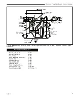
Power Venting System
Model: PVS-1
for use with
Decorative Gas Appliance Models:
NVC33VN/VP, NVC36VN/VP,
NVC39VN/VP, NVC43VN/VP
Homeowner’s Installation &
Operating Manual
CERTIFIED
DESIGN
CERTIFIED
PLEASE KEEP THIS MANUAL FOR FUTURE REFERENCE
51810 1/06 Rev. 2


