background image


15150 25th Avenue North, Minneapolis, MN  55447-1981 

Phone 763-476-8600     Fax 763-476-4092 

For Service:   MN 763-476-4191   IA 319-632-4288   NE 402-330-2323 

Visit us at:  

www.productivity.com

     Productivity is ISO 9001:2000 Certified 

Productivity Inc

®    

Makino EDGE-2 PRE-INSTALLATION CHECKLIST 

– Rev 01/2009 


Installation of your new Makino EDGE-2 can be smooth and rapid if preparations are made prior to the delivery of 
your machine.  Any questions regarding machine installation should be directed to our service department for 
clarification.  We hope this checklist will aid in a rapid installation of your new machine.  

NOTE:  The following 

must be completed prior to our service technician arriving to install your new machine.
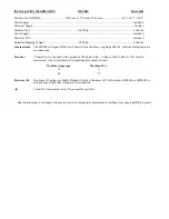


¾

  Power Requirements for your machine:    30 Amp/3 phase/9kVa 


*Voltage of 200 to 480 at +/- 10% must be maintained.  If not, an Automatic Voltage Regulator should be used. 
Proper voltage per machine specifications should be ready at machine site. 

Do NOT power up the machine.


See Makino Installation Manual for more information, or contact our Service Department with any 
questions.


¾

  Customer should furnish and have available the proper supply and types of lubricants required for machine 

operation. 
 

ITEM CAPACITY 

FLUID 

TYPE 

Dielectric Oil 

52.8 Gal 

IONO Plus+ 

You will need to have Dielectric Oil on hand for installation.  Contact our Service Department for more 
information. 
 

¾

  Air lines should be routed to the machine location and operational for proper air pressure.   


Clean, Dry Compressed Air of 70 psi. must be available; less than 40% relative humidity; In-line water trap 
recommended.  


¾

  Machine location should be planned to allow enough room for access panels to be opened and serviced with 

ease.  A minimum of 36” is required around the machine for operator and maintenance access. 
 

¾

  Weight requirements should be checked to insure that the surface below the machine will have sufficient 

strength for support and stability. The machine must be set on a solid, sound and stable, steel bar-reinforced 
concrete slab poured directly on the grade.  In general, the 6” concrete floor on industrial buildings is suitable 
for machine placement. 
 

¾


The EDGE-2 is best moved with a forklift.  See Makino Installation Manual for lifting instructions. 
**NOTE 1: LIFTING EQUIPMENT, ROPES, SCHACKLES, LIFTING BARS, LIFTING BEAMS, ETC. ARE 
OPTIONAL EQUIPMENT AND ARE NOT PROVIDED WITH THE MACHINE.  ITEMS MUST BE 
PURCHASED PRIOR TO MACHINE DELIVERY IF LIFTING WITH OVERHEAD/CRANE.  

Upon arrival of 

your machine, uncrate and immediately check for visible damage. 


SHIPPING WEIGHT 

SHIPPING DIMENSIONS OF MACHINE 

8,377 # (Skidded/wrapped) 

91" L x 91" W x 96" H (Skidded/wrapped) 

See Makino Installation Manual for floor space requirements/dimensions – will vary depending upon the 
options you purchase. 


¾


Remove as much preservative from the machine as possible without having to power up (tables – 
slides, pulleys, etc.).  We recommend mineral spirits to clean.  Apply oil when finished to prevent rust. 


PLEASE FORWARD THIS TO THE APPROPRIATE PERSON. THANK YOU. 

Summary of Contents for EDGE-2

Page 1: ...uted to the machine location and operational for proper air pressure Clean Dry Compressed Air of 70 psi must be available less than 40 relative humidity In line water trap recommended Machine location...

Page 2: ...portation is recommended Electrical 3 Phase Power is required with a ground of 100 ohms or less Voltage of 200 to 480 at 10 must be maintained If not an Automatic Voltage Regulator should be used Mach...

Page 3: ...ays Makino Customer Support 1st Release Date July 20 2000 Copyright 2000 Makino Inc All Rights Reserved No part of this manual may be reproduced or transmitted by any means or in any form to parties o...

Page 4: ...es an existing hazardous condition with a high probability of death or severe injury Precau tions must be taken immediately to prevent personal injury or death A WARNING icon proceeds each warning sta...

Page 5: ...tion of rotation CNC Computerized Numerical Control control unit for machine tool system cw clockwise direction of rotation DEC Deceleration axis slow down for reference operations DI Dielectric i e D...

Page 6: ...hine doit savoir comment l utiliser sans danger et correctement afin d eviter tout accident HINWEIS Alle Personen die nur Teile des Handbuches oder kein Englisch verstenen m ssen sich dieses Handbuch...

Page 7: ...XLGH 20ED3A1863 E v CONTENTS Chapter 1 Safety Precautions Chapter 2 Specifications Chapter 3 Installation Process Overview Chapter 4 Pre Delivery Preparations Chapter 5 Machine Delivery Appendix A Con...

Page 8: ...vi 3UH QVWDOODWLRQ XLGH...

Page 9: ...3UH QVWDOODWLRQ XLGH 01_20ed3a Safety fm Makino EDGE2 Ram Electrical Discharge Machine with MGF Control Chapter 1 Safety Precautions For a Safe Working Environment...

Page 10: ...fting Safety 1 11 1 6 1 Slings 1 11 1 6 2 Chains 1 11 1 6 3 Hooks 1 12 1 6 4 Eye Bolts 1 12 1 6 5 Rings 1 12 1 6 6 Lifting the Machine or Components 1 13 1 6 7 Lifting Workpieces and Fixtures 1 13 1 7...

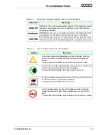
Page 11: ...01_20ed3aSafety fm 3UH QVWDOODWLRQ XLGH 1 11 Installation Safety Instructions 1 25...

Page 12: ...3UH QVWDOODWLRQ XLGH NOTES SKETCHES...

Page 13: ...their intended use 1 2 General Safety Safety precautions or requirements discussed in Makino guides or manu als do not supersede any safety requirements imposed by local state or federal governments...

Page 14: ...operate this machine contact your Makino service group for answers to any questions about safety and your Makino machine 1 2 1 Danger Warning Caution Statements and Symbols It is important that all em...

Page 15: ...E 1 2 SAFETY SYMBOL SHAPES AND THEIR MEANING Symbol Meaning A triangle or diamond shaped safety symbol indicates a hazard exists in the area or behind the enclosure where the symbol is placed The symb...

Page 16: ...tion should be safeguarded to the greatest extent possible for all machining operations In addition to panel locks interlocks and guarding certain areas of the machining center are color coded for saf...

Page 17: ...onto the lockout device All persons performing maintenance on the machine at the same time shall install their own padlock onto the lockout device 6 Disconnect the main power of all power sources i e...

Page 18: ...quids Improperly stored chemicals or flammable materials and any unusual fumes Loose worn or broken flooring Slippery broken or unstable platforms Missing broken or unstable handrails Avoid making sud...

Page 19: ...eglect your responsibility to ensure that all machining centers are operated maintained and equipped with complete regard for oper ator safety Only qualified personnel trained in safety and all machin...

Page 20: ...the machine and auxiliary components moving members and range of movement which may create pinch points Always be cautious of these areas Avoid pinch points entirely during machine operation Keep the...

Page 21: ...switches interlock circuitry etc Never operate the machine with any safety device disabled or removed or any cover open or removed Do not allow yourself to become trapped or caught in pinch points Alw...

Page 22: ...nd normal operations can safely be resumed Never step on machine covers as they can become slippery during normal operation and are not designed to support your weight Never perform grinding operation...

Page 23: ...dance with industry standards Any lifting device that cannot be repaired must be destroyed 1 6 1 Slings Use nylon slings when lifting irregularly shaped objects and Never exceed the lifting capacity o...

Page 24: ...xcess of 480 C 900 F Heat exposure can change the physical properties of the stock and create an unsafe eye bolt Never use an inch eye bolt in a metric thread or vice versa Use inch series thread eye...

Page 25: ...In addition Only qualified riggers should perform machine lifting operations Never place any portion of your body beneath a suspended object Lift the machining center only at the designated lifting po...

Page 26: ...fore disassembling any portion of their drive train Be familiar with and adhere to safe lifting practices described in section 1 6 before lifting the machine or components Never return the machining c...

Page 27: ...electrical control cabinet Electrical Maintenance Equipment Use only industry standard approved electrical testing equipment Volt Ohm Meters Oscilloscopes Static Ground Wrist Straps Machine Grounding...

Page 28: ...ve the workpiece 3 Abnormal Machining Detector stops the machining process if an arc occurs for an extended duration During an arc the head retracts to clear the problem If the head retracts beyond a...

Page 29: ...e mounting method of the electrode workpiece and fixture so that electrical discharge does not occur near the surface of the dielectric Monitor the machining process Never leave the machine totally un...

Page 30: ...el must be 50mm above the top of the work piece 3 Fire hazard from machine platen contacting a clamp Ensure moving machine members will clear clamps workpiece and fixturing 4 Fire hazard due to arcing...

Page 31: ...01_20ed3a Safety fm 1 19 3UH QVWDOODWLRQ XLGH FIGURE 1 1 EDM FIRE CONDITIONS Legend 1 Electrode 2 Jet Nozzle 3 Workpiece 4 Table 5 Dielectric 6 Clamp 7 Shank...

Page 32: ...ions Automatic Fire Extinguisher and other fire related equipment see sec tion 1 9 1 pg 1 16 Descriptions operational detail and precautions related to these safety features are described in the Opera...

Page 33: ...ety Labels Labels attached to the machine at specific areas identify safety risks and provide important instructions that must be read and followed Machine safety labels Figure 1 3 Oilmatic safety lab...

Page 34: ...1 22 3UH QVWDOODWLRQ XLGH FIGURE 1 4 OILMATIC SAFETY LABELS...

Page 35: ...stopped and the control is in the STOP or RESET status DRY RUN machining programs to verify that there is no chance of any interference between any machine parts fixturing and workpiece prior to unatt...

Page 36: ...evice will operate properly and safely under the proposed operating conditions Prior to unattended operation prove out part programs to ensure clear ance between machine parts fixturing and the workpi...

Page 37: ...o the installation instructions provided in the Pre Installa tion Guide Review the general lifting safety rules in section 1 6 and the specific procedures in the Pre Installation Guide prior to moving...

Page 38: ...1 26 3UH QVWDOODWLRQ XLGH NOTES SKETCHES...

Page 39: ...3UH QVWDOODWLRQ XLGH 02_20ed3a Specifications fm Makino EDGE2 Ram Electrical Discharge Machine with MGF Control Chapter 2 Specifications Machine Unit and Control Specifications...

Page 40: ...4 2 Table 2 11 2 4 3 Axis Components Spindle Ram Saddle 2 12 2 4 4 Accuracy 2 12 2 4 5 ATC 2 14 2 4 5 1 Maximum Electrode Size 2 14 2 4 6 Dielectric Fluid Supply 2 15 2 4 6 1 Dielectric Fluid 2 16 2...

Page 41: ...tool should be placed with sufficient clearance to Access the rear of the machine and all auxiliary components Completely open all cabinet doors and panels Prevent interference and potential pinch poi...

Page 42: ...2 2 3UH QVWDOODWLRQ XLGH 2 2 1 Layout Drawings FIGURE 2 1 EDGE2 FRONT VIEW Legend 1 Work Table 5 NC Unit 2 ATC 6 Flexible Pendent Panel 3 Ram 7 Work Tank 4 Main Operation Panel...

Page 43: ...Specifications fm 2 3 3UH QVWDOODWLRQ XLGH Legend 1 Dielectric Unit 5 Air Filter Regulator 2 Oilmatic 6 Automatic Fire Extinguisher 3 Ram 7 Work Tank 4 NC Unit 8 Work Table FIGURE 2 2 EDGE2 LEFT AND R...

Page 44: ...2 4 3UH QVWDOODWLRQ XLGH FIGURE 2 3 EDGE2 GENERAL ARRANGEMENT DRAWING Legend 1 Dielectric Unit 3 NC Unit 2 Oilmatic 4 Main Operation Panel...

Page 45: ...tions The machine should be placed on a continuous concrete pad The required floor space including standard accessories is 2225 2370mm for a standard machine The required floor space increases with AT...

Page 46: ...ystems or any source that may affect the machine temperature 2 3 2 Machine Size Machine dimensions are listed in Table 2 2 External dimensions and floor plans are presented in section 2 2 1 TABLE 2 1...

Page 47: ...cal service Use the machine kVa rating when calculating machine electrical consumption Ensure the electrical service voltages meet all requirements Install an additional automatic voltage regulator if...

Page 48: ...permanently piped A pressure switch detects if air pressure drops below 0 3MPa and stops machine operation TABLE 2 4 AIR SPECIFICATIONS Item Specification Standard machines Pressure 0 6MPa Consumptio...

Page 49: ...he electrode is bolted directly to the platen Figure 2 4 shows the platen bolt pattern Machines may also be pur chased with a C axis option which comes with a chuck adapter The C axis may be pur chase...

Page 50: ...efer to your sales order to confirm the head provided on your machine TABLE 2 6 SPECIFICATIONS FOR MA AND MR HEADS Specification Head Type MA MR Speed Rotary Function Selected 10 1000rpm 0 10rpm In Ro...

Page 51: ...ure 2 5 shows table detail and Table 2 7 lists table specifications TABLE 2 7 TABLE SPECIFICATIONS Item Specification Table Size 500x350mm Number of T Slots Size 10mm x 4 rows Maximum Workpiece Weight...

Page 52: ...aintenance to be maintained or guaran teed TABLE 2 8 AXIS COMPONENT SPECIFICATIONS Item Specification X Y Axis Travel 300 250mm Z Axis Travel 250mm Worktank Dimensions WxDxH 650 450 300mm Platen to Ta...

Page 53: ...02_20ed3a Specifications fm 2 13 3UH QVWDOODWLRQ XLGH FIGURE 2 6 AXIS CONFIGURATION AND WORK CUBE Legend 1 Machine Reference 2 Table...

Page 54: ...imum electrode diameter varies by ATC size Maximum electrode length varies with chuck type and work tank posi tion See Table 2 11 Maximum length is based on work tank in full up position TABLE 2 10 AT...

Page 55: ...02_20ed3a Specifications fm 2 15 3UH QVWDOODWLRQ XLGH The maximum electrode length shown in Figure 2 7 is for the work tank in full up position and is also affected by chuck type...

Page 56: ...mum machining For increased accuracy the cooler maintains fluid temperature within a set range of the machine temperature TABLE 2 12 DIELECTRIC SUPPLY Item Specification Fire Extinguisher Automatic Wo...

Page 57: ...mineral fluids and promote longer filter life 3 Intermediate Fluid Provides performance characteristics between those of mineral and synthetic fluids 2 4 7 Machining Power Source Table 2 13 lists the...

Page 58: ...inch Color display MDI Manual Data Input Function Operation Record Display Run Hour Dynamic Graphic Display Routine Functions Automatic Reference Return Measurement Return To Workpiece Zero Position...

Page 59: ...solute Automatic Return Workpiece Edge Positioning Hole Centering Corner Edge Positioning Groove Width Centering Plate Width Centering Cylinder Center Measurement Work Parallelism Measurement Automati...

Page 60: ...hining Condition Output G151 Machining Time Output G152 Machining Status Record Output G153 Data Backup G154 Feature Detail Controlled Axes 5 Simultaneous Control 4 Coordinate Systems Absolute or Incr...

Page 61: ...Linear Interpolation Manual G1 Circular Interpolation G2 CW G3 CCW Taper Interpolation G51 left G52 right G50 can cel Taper Corner Tangential Interpolation G24 Spiral Interpolation G25 Taper Top Bott...

Page 62: ...Common Variables Decimal Point Programming Diameter Compensation 10 precision inch Editing Part Program editing Background editing Program Number Search Program Number Copy Program Number Division Pr...

Page 63: ...02_20ed3a Specifications fm 2 23 3UH QVWDOODWLRQ XLGH NOTES SKETCHES...

Page 64: ...2 24 3UH QVWDOODWLRQ XLGH...

Page 65: ...3UH QVWDOODWLRQ XLGH 03_20ed3a Install Process fm Makino EDGE2 Ram Electrical Discharge Machine with MGF Control Chapter 3 Installation Process Overview...

Page 66: ...erview Contents 3UH QVWDOODWLRQ XLGH 3 1 Overview 3 1 3 2 The Installation Process 3 2 3 2 1 Customer Installation Duties 3 2 3 2 2 FSE Installation and Set up Duties 3 3 3 2 2 1 Machine Installation...

Page 67: ...he success and efficiency of your installation rests in large part on your participation and involvement in the installation process Sixty days before the delivery of your Makino machine take time to...

Page 68: ...ine installation Read the pre installation information in this Guide Follow the instructions in chapter 4 and chapter 5 Use the worksheets provided in chapter 4 to prepare for delivery and installatio...

Page 69: ...on 1 Initial Checks Check the foundation and placement Check the machine for damage or other unacceptable conditions Confirm cleanliness of machine components i e anti corrosive grease is removed Afte...

Page 70: ...Checks and Adjustments Install any required custom programs Check and confirm proper operation of all machine systems and functions i e overtravel switches spindle unclamp etc Verify operation of CNC...

Page 71: ...ts the following be considered regarding on site training We strongly recommend that both the operator s and maintenance personnel are available for this training The job of maintenance is to fix the...

Page 72: ...ol panels and display are explained demon strated and practiced Job Set up Finding program zero and assigning work coordinate offsets is practiced Finding and assigning tool offsets is practiced Tool...

Page 73: ...r experience shows that allowing the operator to become familiar with the basic machining center prior to learning the options is beneficial Due to the nature of available options training is provided...

Page 74: ...3 8 3UH QVWDOODWLRQ XLGH NOTES SKETCHES...

Page 75: ...3UH QVWDOODWLRQ XLGH 04_20ed3a Pre Delivery Prep fm Makino EDGE2 Ram Electrical Discharge Machine with MGF Control Chapter 4 Pre Delivery Preparations...

Page 76: ...n Checklist 4 4 4 2 1 Checklist Questions 4 4 4 2 2 Checklist Instructions 4 4 4 2 3 Completed Checklist Distribution 4 4 4 3 Selecting the Machine Location 4 7 4 3 1 Access 4 7 4 3 2 Manufacturing Pr...

Page 77: ...ne installation Use this Guide to accomplish these pre installation tasks Selecting machine location Access environment and foundation section 4 3 pg 4 7 Dimensional drawings for required floor space...

Page 78: ...blish installation duties MACHINING REQUIREMENTS Determine fixturing needs 3 Identify job and workpieces Identify inspection equipment PERSONNEL REQUIREMENTS Select Operator s Select Programmer s and...

Page 79: ...04_20ed3a Pre Delivery Prep fm 4 3 3UH QVWDOODWLRQ XLGH NOTES SKETCHES...

Page 80: ...any of the requirements on the Pre instal lation Checklist or to inform us of your current status or a delay Contact your distributor sales or service representative Contact Makino Customer Support Pl...

Page 81: ...le Phone 2nd Contact Title Phone 3nd Contact Title Phone Shipping Address Please complete to confirm the data in our records Street P O Box Suite City State Zip Code Billing Address Complete only if d...

Page 82: ...e clean solvent 5 Power cables are installed 3 phase 240 480 VAC source voltage has been routed and con nected to the main disconnect WARNING Do NOT apply power to the machine at this time the FSE wil...

Page 83: ...the machine site that pro vides sufficient width height and swing clearance to accommodate your machine rigging and moving equipment Failure to ensure sufficient mov ing room could result in delays a...

Page 84: ...for the following conditions Dust free well lighted and free of temperature changes Ambient temperature 10 to 35 C optimum 20 1 C Temperature fluctuation less than 1 C 30 minutes Relative humidity 35...

Page 85: ...a special foundation is needed to maintain machine level and alignment If you are considering a special foundation contact Makino When locating the machine on an upper floor of a building be sure to C...

Page 86: ...he operator or programmer has developed a familiarity with the machine This information is provided in the prerequisite area of each course description Course offerings designed to support our EDM cus...

Page 87: ...04_20ed3a Pre Delivery Prep fm 4 11 3UH QVWDOODWLRQ XLGH NOTES SKETCHES...

Page 88: ...4 12 3UH QVWDOODWLRQ XLGH NOTES SKETCHES...

Page 89: ...3UH QVWDOODWLRQ XLGH 05_20ed3a Machine Delivery fm Makino EDGE2 Ram Electrical Discharge Machine with MGF Control Chapter 5 Machine Delivery...

Page 90: ...he Machine 5 2 5 3 Unloading Lifting and Moving 5 3 5 3 1 Lifting and Moving the Machine 5 4 5 4 Leveling 5 7 5 4 1 Check the Precision Level 5 7 5 4 2 Leveling the Machine 5 8 5 5 Initial Cleaning 5...

Page 91: ...rtest installation time Provides maximum training time for operator and maintenance person nel The Installation Process Makino s Installation process includes Pre Installation duties to be performed b...

Page 92: ...r 1 Write on the shipper Received subject to hidden and concealed damage Though rarely a factor this precaution may protect your investment 2 Sign your name After Signing the Shipper 1 Inspect all ite...

Page 93: ...m truck or fork lift of sufficient capacity to lift the machine packing case and ancillary components off the truck 2 Move the machine and the ancillary components to their location Verify there is ad...

Page 94: ...with machine components Use heavy pads or wood blocks at interference points 5 Lift the machine and move to installation site 6 Set 300mm blocking under the machine near each leveling point Lifting an...

Page 95: ...he machine pallet 8 Lilft the machine and remove blocking 9 Set the machine on the leveling bases 10 Unhook the cables and move the crane away from the machine 11 Rough level the machine Setting and L...

Page 96: ...ght to allow the iron to normalize before final leveling 5 4 1 Check the Precision Level 1 Place the level on a clean flat surface that is level enough to give a bubble reading that is not bottomed in...

Page 97: ...the reading Move to the Y axis plane note the reading 3 Adjust the leveling screws to obtain level 4 Repeat the X and Y read ings and level adjustments until the machine is level within 0 03mm 5 Tigh...

Page 98: ...n toxic solvent to remove the corrosion preventative Clean only those areas of the machine you can reach without moving the axes Wipe the machine surfaces dry with a clean dry cloth Do NOT use an air...

Page 99: ...regulator to obtain an output pressure of 0 6MPa To set the pressure 1 Pull up on adjusting cap 1 2 Rotate adjusting cap 1 cw to increase or ccw to decrease until pressure gage 3 reads 0 6MPa 3 Push a...

Page 100: ...urn adjusting cab 4 until the outlet pressure gage 5 reads 0 7MPa Rotate adjusting cap cw to increase or ccw to decrease 3 Turn adjusting caps 2 until pressure gage 1 reads 0 6MPa 4 Push the adjusting...

Page 101: ...switch CB1 is Off 2 Ensure the facility power BUSS or discon nect is Off 3 Perform Lockout Tagout at the facility power BUSS or disconnect 4 Ensure proper cable size and type are used consult electric...

Page 102: ...me Leave the power dis connect turned Off Locked Out and Tagged until the FSE requests that power be turned On Do NOT Apply Power Leave the power BUSS or disconnect Off Locked Out and Tagged The FSE w...

Page 103: ...05_20ed3a Machine Delivery fm 5 13 3UH QVWDOODWLRQ XLGH NOTES SKETCHES...

Page 104: ...5 14 3UH QVWDOODWLRQ XLGH NOTES SKETCHES...

Page 105: ...SSHQGL A1_comb inch to metric conversion fm Appendix A Conversion Factors SI Metric System Basics and Inch Metric Conversion Factors...

Page 106: ...SSHQGL Appendix A Conversion Factors Contents A 1 Introduction A 1 A 2 Metric Basics A 2 A 3 Inch Metric Conversions A 6 A 4 Electrical Consumption A 11 A 5 Conversion Factors for CNC A 11...

Page 107: ...hich designs and produces its equipment in the metric system Currently the JIS Japanese Industrial Standard is used but the world market is driving toward the use of the SI Systeme International d Uni...

Page 108: ...hough most advanced industrial nations use a metric system Most countries are currently moving away from their system to the SI system All Metric systems are based on decimal arithmetic This means tha...

Page 109: ...p femto 10 15 femto 0 0000000000000001 base units f atto 10 18 atto 0 000000000000000001 base unit a More on Metrics For more information on metrics refer to the following publications MACHINERY HAND...

Page 110: ...mula and unit symbol are listed Table A 4 presents SI units with complex names The unit name physical quantity and unit symbol are listed TABLE A 2 BASIC SI METRIC UNITS Basic SI base Units Unit Name...

Page 111: ...cycle s Hz pascal Pressure N m2 Pa tesla Magnetic Flux Density Wb m2 T TABLE A 4 SI METRIC UNITS WITH COMPLEX NAMES SI Units with Complex Names Unit Name Physical Quantity Unit Symbol square meter Are...

Page 112: ...SSHQGL A 6 NOTES SKETCHES...

Page 113: ...be more precise than the original value Know the acceptable tolerances in your field and ensure that converted measurements are appropriate EXAMPLE When converting 50 square feet to square meters the...

Page 114: ...ONS Inch X This Metric X This Inch square inch in 2 sq in x 645 16 square millimeter mm2 sq mm x 0 00155 in 2 x 6 4516 square centimeter cm2 sq cm x 0 1550 x 0 00064516 square meter m2 sq m x 1550 0 s...

Page 115: ...sq yd x 0 76455 cubic meter m3 sq m x 1 307951 yd3 US gallon gal x 0 003785 cubic meter m3 sq m x 264 1720 US gal x 3 785412 liter L x 0 2641720 UK gallon imp gal x 0 004546 cubic meter m3 sq m x 219...

Page 116: ...liter minute liter min L m x 0 264172 UK gallon minute imp gal min x 0 00454609 cubic meter minute meter3 min m3 min x 219 9692 imp gal min cubic feet minute cfm ft3 min x 28 31685 liter minute liter...

Page 117: ...806650 newton meter TABLE A 13 PRESSURE CONVERSIONS Inch X This Metric X This Inch atmosphere atm 14 6959 lb in 2 x 101 325 0 pascal Pa x 0 000009869 atm bar x 100 000 0 pascal Pa x 0 00001 bar x 14...

Page 118: ...WER CONVERSIONS Inch X This Metric X This Inch horsepower hp 550 ft lb s x 745 6999 watt W x 0 001341022 hp x 0 7456999 kilowatt kW x 1 341022 horsepower electric hp x 746 0 watt W x 0 001340483 hp ho...

Page 119: ...ically given in terms of tape length meters or feet Table A 18 presents the number of characters per inch foot meter and page TABLE A 17 ELECTRICAL CONSUMPTION FORMULAE To Calculate Use Formula Ampera...

Page 120: ...SSHQGL A 14 NOTES SKETCHES...

Reviews: