background image

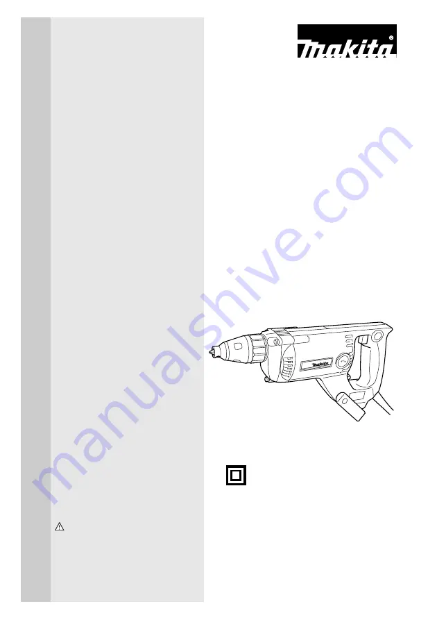
I N S T R U C T I O N   M A N U A L

WARNING:

For your personal safety, READ and UNDERSTAND before using.
SAVE THESE INSTRUCTIONS FOR FUTURE REFERENCE.

Drywall Screwdriver

MODEL 6812

002602

DOUBLE
INSULATION

Summary of Contents for 6812

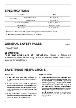
Page 1: ...I N S T R U C T I O N M A N U A L WARNING For your personal safety READ and UNDERSTAND before using SAVE THESE INSTRUCTIONS FOR FUTURE REFERENCE Drywall Screwdriver MODEL 6812 002602 DOUBLE INSULATION ...

Page 2: ... create sparks which may ignite the dust or fumes 3 Keep bystanders children and visitors away while operating a power tool Distrac tions can cause you to lose control Electrical Safety 4 Double insulated tools are equipped with a polarized plug one blade is wider than the other This plug will fit in a polarized outlet only one way If the plug does not fit fully in the outlet reverse the plug If i...

Page 3: ...Keep proper footing and balance at all times Proper footing and balance enables better control of the tool in unexpected situations 14 Use safety equipment Always wear eye protection Dust mask non skid safety shoes hard hat or hearing protection must be used for appropriate conditions Ordinary eye or sun glasses are NOT eye protection Tool Use and Care 15 Use clamps or other practical way to secur...

Page 4: ...The smaller the gage num ber the heavier the cord SPECIFIC SAFETY RULES USB004 2 DO NOT let comfort or familiarity with product gained from repeated use replace strict adherence to screwdriver safety rules If you use this tool unsafely or incorrectly you can suffer serious personal injury 1 Hold tool by insulated gripping surfaces when performing an operation where the cutting tool may contact hid...

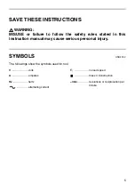
Page 5: ...fety rules stated in this instruction manual may cause serious personal injury SYMBOLS USD201 2 The followings show the symbols used for tool V volts A amperes Hz hertz alternating current no load speed Class II Construction min revolutions or reciprocation per minute n ...

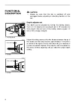
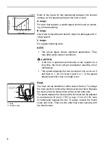
Page 6: ... One full turn of the locking sleeve equals 1 5 mm 1 16 change in depth Adjust the locking sleeve so that the distance between the tip of the locator and the screw head is approximately 1 mm 3 64 as shown in the figures Drive a trial screw into your material or a piece of duplicate material If the depth is still not suitable for the screw continue adjusting until you obtain the proper depth settin...

Page 7: ...g switch action This tool has a reversing switch to change the direction of rotation Move the reversing switch lever to the A side for clockwise rotation or the B side for counterclockwise rotation CAUTION Always check the direction of rotation before operation Use the reversing switch only after the tool comes to a complete stop Changing the direction of rotation before the tool stops may damage ...

Page 8: ... tool malfunction The speed adjusting dial can be turned only as far as 5 and back to 1 Do not force it past 5 or 1 or the speed adjusting function may no longer work Hook The hook can be installed on either side of the tool To change the hook position remove the thumb screw and hook Replace the hook so that its bent portion will be on the other side The space between the hook and the tool itself ...

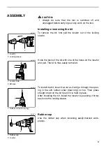
Page 9: ... easily removed To install the bit insert it as far as it will go through the open ing in the soft rubber collar dust ring on top Then press straight down on the bit tip until it is held in place After installing the bit install the locator by pushing it firmly back onto the locking sleeve Rubber cap Use the rubber cap when fastening easily marked work pieces 1 Locator 2 Locking sleeve 1 2 002651 ...

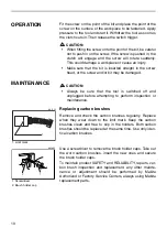
Page 10: ... sure that the tool is switched off and unplugged before attempting to perform inspection or maintenance Replacing carbon brushes Remove and check the carbon brushes regularly Replace when they wear down to the limit mark Keep the carbon brushes clean and free to slip in the holders Both carbon brushes should be replaced at the same time Use only iden tical carbon brushes Use a screwdriver to remo...

Page 11: ...ol specified in this manual The use of any other accessories or attachments might present a risk of injury to persons Only use accessory or attachment for its stated purpose If you need any assistance for more details regarding these accessories ask your local Makita service center Phillips bit 2 45 ...

Page 12: ...Memo 12 ...

Page 13: ...13 Fold Cut Stamp Timbre Makita Canada Inc 1950 Forbes Street Whitby Ontario L1N 7B7 ...

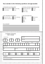
Page 14: ...e Paste Paste Paste Paste Paste 1 This product was purchased from Industrial Supply Other Tool Distributor Hardware lumber Store 2 Use of the product is intended for 5 Any comments Home maintenance Other Industrial maintenance Construction trade 3 How did you first learn of Makita Power Tools Catalog Other From dealer Magazine Newspaper Store display 4 Most favored points are Makita Brand Power Fe...

Page 15: ...e Bégin Ville St Laurent Quebec 514 745 5025 1 888 745 5025 H4R 1X1 Montreal Les Saules 1200 St Jean Baptiste Unit 106 Les Saules 418 871 5720 1 800 663 5757 Quebec G2E 5E8 Quebec Nepean 203 Colonnade Road Unit 6 Nepean 613 224 5022 1 888 560 2214 Ontario K2E 7K3 Ottawa London 317 Adelaide St S Unit 117 London 519 686 3115 1 800 571 0899 Ontario N5Z 3L3 Whitby 1950 Forbes St Whitby Ontario L1N 7B7...

Page 16: ...the Makita tools No dealer or his agent or employee is authorized to extend or enlarge upon this warranty by any verbal or written statement or advertisement MAKITA DISCLAIMS LIABILITY FOR ANY IMPLIED WARRANTIES INCLUDING IMPLIED WARRANTIES OF MERCHANTABILITY AND FITNESS FOR A SPECIFIC PURPOSE AFTER THE ONE YEAR TERM OF THIS WARRANTY This Warranty gives you specific rights The provisions contained...

Reviews: