


Models No.
Description
PRODUCT
C
ONCEPTION AND MAIN APPLICATIONS
S
pecification
S
tandard equipment
O
ptional accessories
< Note > The standard equipment for the tool shown may differ from country to country.
P 1 / 17
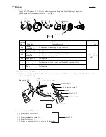
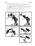
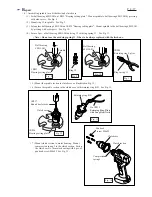
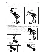
T
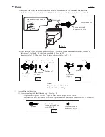
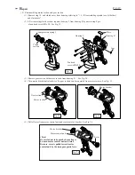
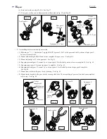
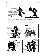
ECHNICAL INFORMATION
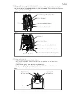
Dimensions (mm [inch])
Height (H)
Length (L)
190 [7-1/2]
266 [10-1/2]
With BH1220
With BH1233
289 [11-3/8]
Width (W)
71 [2-13/16]
BFH040, BFH040F, BFH090, BFH090F, BFH120F
12V Cordless Screwdrivers
The above cordless screwdriver series enable you to work
also in the hazardous location which is defined by
UL1604, Class I, Division 2.
The conformation to UL1604, Class I, Division 2 has been achieved by using
1. Brush-less DC motor for spark-free armature rotation.
2. Battery inter lock system
In addition to the above features, they have the following features.
* Soft start for suppressing starting shock
* Delayed restarter for avoiding unintentional over fastening
* Indication lamp, informing operator of the result of
fastening
* Battery BH1220 ...................................................... 2 pcs.
* Charger DC14SA .................................................... 1 pc.
* Torque adjust tool ................................................. 1 pc.
* Accessory case ........................................................ 1 pc.
* Steel carrying case .................................................... 1 pc.
* Battery BH1220
* Battery BH1233
* Charger DC14SA
* Charger DC24SA
* Adjust grip
* ADP 03 Automatic Refreshing Adapter
Model No.
No load speed : min
-1
= rpm
Fastening torque
: N.m
(in.lbs)
Battery
Electric brake
Driving shank
LED Job Light
Torque adjustment
Soft starter
Reverse switch
Over load protector
Net weight
: Kg (lbs)
Type of cell
Voltage : V
Capacity : Ah
Ni-MH
12
Hex 6.35mm (1/4")
2.0 Ah with battery BH1220
3.3 Ah with battery BH1233
400
1.5 (3.3)
1.8 (4.0)
Yes
Yes
Yes
Yes
Yes (Adjust grip is required.)
BFH040F
BFH040
BFH090
BFH090F
BFH120F
0.8 - 4.5
(7 - 40)
3.4 - 9.0
(30 - 80)
5 - 12
(44 - 106)
0.8 - 4.5
(7 - 40)
3.4 - 9.0
(30 - 80)
5 - 12
(44 - 106)
w/ 2.0Ah battery
w/ 3.3Ah battery
Hard joint
Soft joint
Yes
No
No
Yes
Yes
They come to market wit the following model name and the specification.
BFH040
BFH040SAE
BFH040F
BFH040FSAE
BFH090
BFH090SAE
BFH090F
BFH090FSAE
BFH120F
BFH120FSAE
* Battery 1220 x 2pcs.
* Charger DC14SA
* Torque adjsut grip
* Accessory case
* Steel carrying case
with
H
L
W


