background image

C

ONCEPT AND MAIN APPLICATIONS

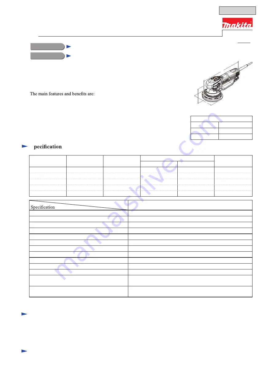
BO6050 is a 150mm (6”) Random orbit sander developed as the successor to 

the current model BO6040.

• Excellent operability thanks to the following:

  - Toolless pad change

  - Ergonomically designed soft palm grip

  - Slim skirt

• Change lever protection system

S

Model

BO6050

Orbits per minute: opm= min

-1

1,600 - 6,800

Sanding strokes: spm= min

-1

3,200 - 13,600

Pad speed in Roto-orbit mode: rpm= min

-1

140 - 600

Paper fastening system

Hook & loop

Pad diameter: mm (")

ø150 (6)

Abrasive disc diameter: mm (")

ø150 (6)

Orbit diameter: mm (")

ø5.5 (7/32)

Pad brake

Yes

Variable speed control

Yes

Soft start

Yes

Constant speed control

Yes

Power supply cord: m (ft)

European countries: 4.0 (13.1), Australia, Brazil: 2.0 (6.6)

Other countries: 2.5 (8.2)

Weight according to

EPTA-Procedure 01/2003

*

1

: kg (lbs)

2.6 (5.7)

*1

 With Dust nozzle

Dimensions: mm ( " )

Length (L)

330 (13)

Width (W)

155 (6-1/8)

Height (H)

145 (5-3/4)

L

W

H

Voltage (V)

Current (A)

Cycle (Hz)

Continuous Rating (W)

Max Output (W)

Input

Output

110

7.2

50/60

750

350

750

120

6.6

50/60

---

350

750

220

3.6

50/60

750

350

850

230

3.5

50/60

750

350

850

240

3.3

50/60

750

350

850

Abrasive disc 150-120

*

2

Dust nozzle

Side grip

Pad protector

Plastic carrying case

*2

 for some countries only

Abrasive discs 150-40/60/80/120/180/240/400

Pad 150 (Soft, hard, super soft)

Pad 130 (Polishing)

Wool pad

Felt pad

Front cuffs 24

Front cuffs 22

S

tandard equipment

O

ptional accessories

T

ECHNICAL INFORMATION

PRODUCT

P 1/ 28

Model No.
Description

150mm (6") Random Orbit Sander

BO6050

November 2015

OFFICIAL USE 

for ASC & Sales Shop

Summary of Contents for BO6050

Page 1: ...ntries 4 0 13 1 Australia Brazil 2 0 6 6 Other countries 2 5 8 2 Weight according to EPTA Procedure 01 2003 1 kg lbs 2 6 5 7 1 With Dust nozzle Dimensions mm Length L 330 13 Width W 155 6 1 8 Height H...

Page 2: ...E 20 12 2 press fitting Ball bearing 6001DDW press fitting Ball bearing 6804LLU removing Outer spindle complete removing Armature press fitting Ball bearing 6906DDW and Spur gear 31 removing Outer spi...

Page 3: ...the portions designated with black triangle Makita Grease FA No 2 to the portions designated with gray triangle 2 LUBRICANT AND ADHESIVE APPLICATION LUBRICANT Fig 1 15 15 44 44 O ring 26 Whole portion...

Page 4: ...stening Baffle plate 58 to Motor housing 71 fastening Brush holder 76 to Motor housing 71 fastening Rear cover 80 to Motor housing 71 fastening Nozzle complete 82 to Rear cover 80 screwing to Inner sp...

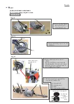
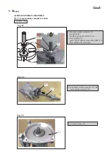
Page 5: ...er guard 23 3 Remove Head cover set R 19 by unscrewing four 4x18 Tapping screws 20 and one 4x65 Tapping screw 18 Remove Shaft lock complete 30 Note Compression spring 4 31 may remain in Head cover set...

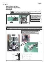
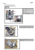
Page 6: ...ng four 4x30 Tapping screws 24 7 Remove Retaining ring S 10 41 with 1R291 The following parts are removed from Inner spindle complete 36 Cover 37 Flat washer 10 38 Thrust needle gauge 39 O ring 26 40...

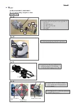
Page 7: ...gear 34 15 Plate 35 Inner spindle complete Note The legs of 1R269 have to be fixed with Water pump pliers because its claw cannot firmly fit to the groove of Internal gear 34 See the center photo in...

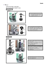
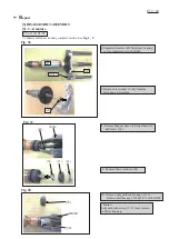
Page 8: ...DW 32 with 1R269 Note Do not reuse Ball bearing 6001DDW 32 13 Unscrew three M4x12 Pan head screws 28 32 Fig 14 Fig 15 1R269 28 29 Do not re use the parts items designated with this mark because it is...

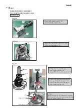
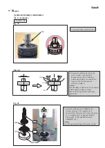
Page 9: ...e 29 by pressing with Arbor press Fig 16 Fig 17 Fig 18 ASSEMBLING 26 1R291 26 1R258 1R258 27 29 1R273 27 1R232 1R232 27 27 29 1R273 1 Set Outer spindle complete 29 on the Base of Arbor press Pass Ball...

Page 10: ...1R252 29 16 Note Spiral bevel gear 43 16 cannot rotate smoothly if it is mounted to the lower position than the edge of Outer spindle complete 29 29 25 25 29 1R252 16 7 Put Spiral bevel gear 43 16 to...

Page 11: ...Inner spindle complete 35 into Outer spindle complete 29 Fig 22 Fig 23 Fig 24 32 1R033 11 Assemble Plate 15 9 Pass Inner spindle complete 35 through 1R033 Put Ball bearing 6001DDW 32 to Inner spindle...

Page 12: ...t Ball bearing 6001DDW 32 with 1R034 Press Internal gear 34 12 with Arbor press Note Do not press Internal gear 34 12 too hard after seating 1R034 1R027 14 Fasten three M4x12 Pan head screws 34 to Bal...

Page 13: ...g it with four 4x30 Tapping screws 24 18 Adjust Plate 15 so that its notches cross with the line of Armature shaft by 90 degrees 19 Set Change knob 2 to Random orbit mode Assemble Top cover 7 2 25 lin...

Page 14: ...by unscrewing one 4x18 Tapping screw 81 3 Move Spiral spring from Carbon brush 78 to make the Carbon brush free from the Spring Remove Carbon brush 78 by pulling up 4 Remove Armature together with Ge...

Page 15: ...from Gear housing cover complete 43 with 1R045 7 Remove Flat washer 10 48 from the drive end of Armature 8 Remove Magnet sleeve 55 together with Self lock 6 56 9 Remove Wave washer 6 54 10 Remove Laby...

Page 16: ...ete 43 by passing through Flat washer 10 48 and Ball bearing 6000DDW 47 Note Do not forget assembling Flat washer 10 48 1R033 2 Press down Self lock 6 56 until Wave washer 6 54 gets flat Magnet sleeve...

Page 17: ...hange knob 2 to Roto orbit mode 1 Disassemble Gear housing complete section in the order of Fig 3 8 4 Remove O ring 65 17 from Top cover 7 5 Remove Spur gear 31 9 with 1R045 from Top cover 7 1R045 3 U...

Page 18: ...ng Top cover 7 with 1R232 press Spur gear 31 9 with Arbor press 1 Applying 1R031 to Ball bearing 6804LLU 8 press it with Arbor press 8 1R269 Descriptions 9 2 1 3 5 7 4 6 4 1 1 1 1 1 1 1 1 1 8 9 17 1 4...

Page 19: ...riangle mark to the direction shown in photo 5 Tighten Change knob with one 4x14 Tapping screw 1 while maintaining direction of Triangle mark to the same direction in step 4 7 Demonstrate if Change kn...

Page 20: ...ng 71 1 Disassemble Gear housing complete section in the order of Fig 3 8 2 Disassemble Armature from Motor housing See Fig 32 34 7 Lift up Rear switch lever 65 57 DISASSEMBLING 6 Separate Switch knob...

Page 21: ...ch knob 61 to the framed portion of Front switch lever 62 passing through the hole of Motor housing 71 5 Push Front switch lever 62 in a direction designated with yellow arrow while holding the Switch...

Page 22: ...P 22 28 Repair 3 DISASSEMBLY ASSEMBLY 3 5 Front switch lever Rear switch lever Fig 57 9 Assemble Baffle plate 58 by tightening with two 4x75 Tapping screws 57 ASSEMBLING 57 57 58...

Page 23: ...Switch knob Brush holder Switch knob side Brush holder Dust nozzle side Dust nozzle Terminal block Switch Insulated terminal Noise suppressor if used Grounding terminal if used This lead wire may be w...

Page 24: ...eld lead wires in Motor housing Field lead wire white Field Motor housing Route Field lead wires red white through the Motor housing s opening of top left side viewing from Switch knob assemble side R...

Page 25: ...k Field lead wire white Put Field lead wire white to this groove Fix the following Lead wires in these Lead wire holders two Lead wires black connected to Closed end terminal Field lead wire white Put...

Page 26: ...n Lead wire white Lead wire black Dial of Controller Dial of Controller Wiring on Motor housing Switch Knob side Pick up coil cover Mount Pick up coil to Pick up coil cover as drawn Put Field magnet l...

Page 27: ...erminal block in Lead wire holder A Tighten Lead wires connected to Terminal block between this Lead wire holder and Terminal block Put Lead wire red of Controller to this lead wire holder Make sure t...

Page 28: ...the lead wire clear to the same space in case that Noise suppressor with grounding lead wire is used Put Lead wires clear of Noise suppressor to this Lead wire holder if Noise suppressor with groundin...

Reviews: