


July 2015
OFFICIAL USE
for ASC & Sales Shop
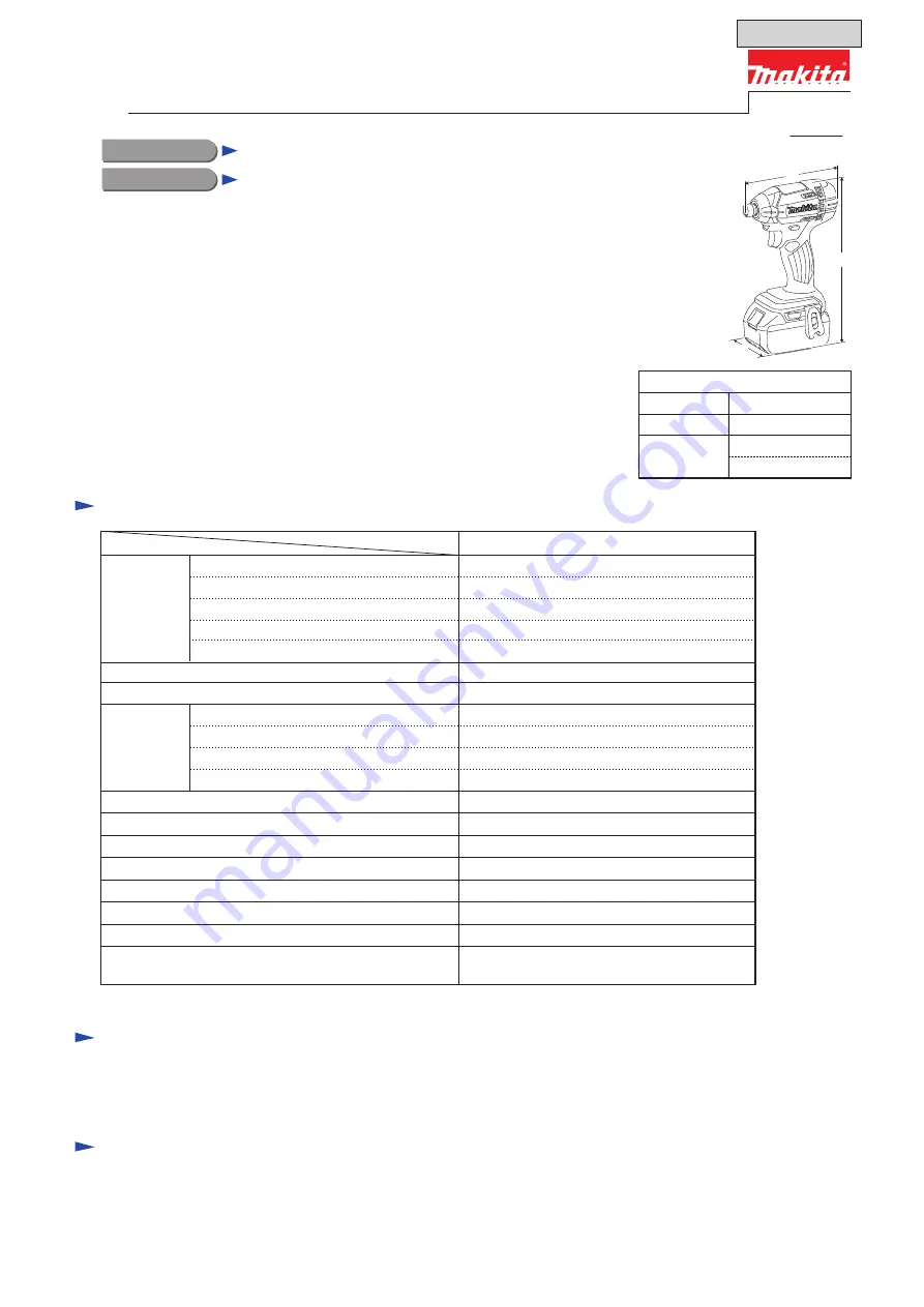
Cordless Impact Driver
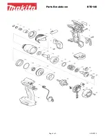
PRODUCT
P 1/ 27
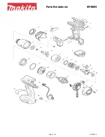
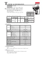
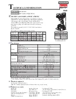
Model No.
DTD152
Description
T
ECHNICAL INFORMATION
S
pecification
S
tandard equipment
O
ptional accessories
Battery
No load speed: min-ı= rpm
Impacts per minute: min-ı= ipm
Max. tightening torque
*3
: N·m [kgf·cm] (in·lbs)
Charging time (approx): min
Capacities
Electric brake
Reverse switch
Weight according to
EPTA-Procedure 01/2003: kg (lbs)
Variable speed control by trigger
Capacity: Ah
Cell
Voltage: V
18
0 - 2,900
0 - 3,500
165 [1,680] (1,460)
Standard bolt
High strength bolt
Machine screw
Driving shank
M5 - M16 (3/16 - 5/8")
M5 - M12 (3/16 - 1/2")
Coarse-thread
22 - 125mm (7/8 - 4-7/8")
M4 - M8 (5/32 - 5/16")
Yes
Yes
Yes
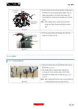
LED job light
Yes
1.3 (2.8)
*
1
or
1.5 (3.3)
*
2
1.3, 1.5, 2.0, 3.0, 4.0, 5.0
Energy capacity: Wh
24, 27, 36, 54, 72, 90
Li-ion
240
15, 15, 24, 22, 36, 45 with DC18RC
6.35mm (1/4") Hex
Max output (W)
Socket bits
Drill chucks
Drill bits with 6.35mm Hex shank
Hole saws for impact driver
Bit piece
Stopper for impact driver
Hook set (Belt clip)
Battery protectors
Li-ion Battery BL1815
Li-ion Battery BL1815N
Li-ion Battery BL1820
Li-ion Battery BL1830
Li-ion Battery BL1840
Li-ion Battery BL1850
Charger DC18SD
Charger DC24SC
Fast charger DC18RC
Automotive charger DC18SE
Four Port Charger DC18SF
Two Port Fast charger DC18RD
Belt clip
Battery
*
4
, Battery cover
*
5
Charger
*
4
, Plastic carrying case
*
4
,
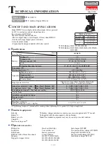
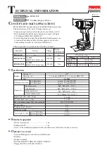
Dimensions: mm (")
Width (W)
Height (H)
Length (L)
79 (3-1/8)
137 (5-3/8)
238 (9-3/8)
*
2
C
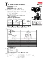
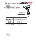
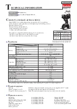
ONCEPT AND MAIN APPLICATIONS
Model DTD152 is a cordless impact driver powered by 18V Li-ion battery
and developed for main applications such as tightening of self-drilling screws or
light duty machine screws.
The main features and benefits are:
• High rotational speed: 2,900 rpm-ı
• Compact and lightweight design
This product is compatible with the following 18V Li-ion batteries:
BL1815 (1.3Ah)/ BL1815N (1.5Ah)/ BL1820 (2.0Ah)/
BL1830 (3.0Ah)/ BL1840 (4.0Ah)/ BL1850 (5.0Ah)
220 (8-5/8)
*
1
*3
Tightening torque at 3 seconds after seating, when tightening M14 (grade 10.9) high strength bolt.
*4
Battery, charger and plastic carrying case are not supplied with “Z” model.
*5
Supplied with the same quantity of extra Battery.
Note:
The standard equipment may vary by country or model variation.
*1
With Battery BL1815/ BL1815N/ BL1820
*2
With Battery BL1830/ BL1840/ BL1850
Specification
Model
DTD152
H
W
L