
P 1/ 1
2
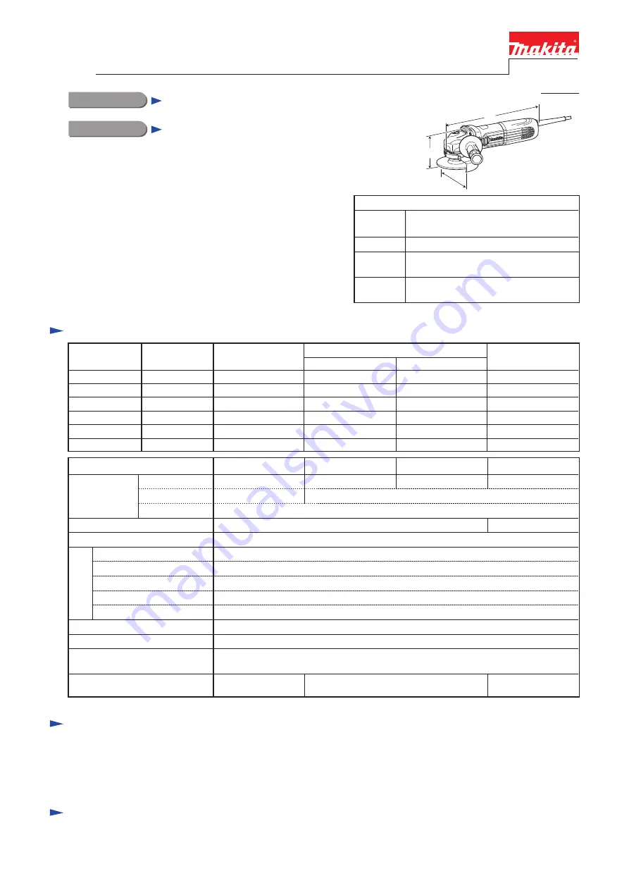
Model No.
GA4040C/GA4042C, GA4540C/GA4542C,
GA5040C/GA5042C, GA6040C/ GA6042C
Dimensions: mm (")
Width (W)
Height (H)
Length (L)
Model No.
303 (11-7/8)
GA4040C/GA4042C, GA4540C/GA4542C,
GA5040C/GA5042C, GA6040C/ GA6042C
117 (4-5/8), 130 (5-1/8),
140 (5-1/2), 171 (6-3/4)
111 (4-3/8), 116 (4-9/16),
116 (4-9/16), 116 (4-9/16)
*
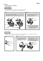
1
Anti-restart function is available for the following models only:
GA4040C, GA4540C, GA5040C, GA6040C
PRODUCT
Description
Angle Grinders 100mm (4"), 115mm (4-1/2"),
125mm (5"), 150mm (6")
L
H
W
C
ONCEPT AND MAIN APPLICATIONS
S
tandard equipment
Note:
The standard equipment for the tool shown above may vary by country.
1,400W Angle grinder series models; GA4040C/ GA4042C,
GA4540C/ GA4542C, GA5040C/ GA5042C and GA6040C/
GA6042C are successor models of 9560 series models, featuring:
•
"
Super Joint System II
"
developed for effective vibration
absorption
• Electronic current limiter, speed control and soft start
• Anti-restart function
*
1
• Re-designed durable gear housing
• Ergonomically best possible barrel grip
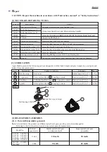
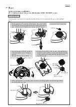
Side grip ............................................... 1 (normal type or anti-vibration type)
Lock nut wrench ................................... 1
Depressed center wheel ........................ 1 (100mm for GA4040C/ GA4042C, 115mm for GA4540C/ GA4542C,
125mm for GA5040C/ GA5042C, 150mm for GA6040C/ GA6042C)
O
ptional accessories
Depressed center wheels
Rubber pads
Dust collecting wheel guards
Abrasive discs
Wire brushes
Wheel covers for wire brushes
Diamond wheels
Abrasive cut off wheels
Wheel covers
Sanding lock nut
etc.
S
pecification
Continuous Rating (W)
Voltage (V)
Cycle (Hz)
Input
Output
840
Max. Output (W)
110
120
220
230
240
13
12
6.7
6.4
6.1
50/60
50/60
50/60
50/60
50/60
1,400
1,400
1,400
1,400
1,400
2,100
2,100
1,800
2,000
2,100
Current (A)
840
127
12
50/60
---
2,000
840
840
840
840
*2
with Side grip, Wheel cover, Inner flange, Lock nut
Model No.
No load speed: min.
ˉ
¹=rpm
Diameter
Hole diameter
Wheel size:
mm (")
Protection against electric shock
Power supply cord: m (ft)
Weight according to
EPTA-Procedure 01/2003
*
2
: kg (")
GA4040C/ GA4042C
GA6040C/ GA6042C
100 (4)
115 (4-1/2)
European countries except UK: 4.0 (13.2), Brazil, Australia: 2.0 (6.6)
Other countries including UK: 2.5 (8.2)
2,800 - 11,000
150 (6)
Double insulation
22.23 (7/8)
16 (5/8)
Max. thickness
6 (1/4)
Shock absorbing System
Mechanical brake
Super Joint System II
Yes
Yes
Yes
GA4040C, GA4540C, GA5040C, GA6040C: Yes/ GA4042C, GA4542C, GA5042C, GA6042C: No
Constant speed control
Variable speed control by dial
Soft start
Electronic current limiter
Anti-restart function
Electronic
control
Yes
No
GA4540C/ GA4542C
125 (5)
2.3 (5.2)
2.5 (5.4)
2.6 (5.6)
GA5040C/ GA5042C
4,000 - 9,000
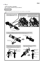
T
ECHNICAL INFORMATION


