
Model No.
Description
PRODUCT
C
ONCEPT AND MAIN APPLICATIONS
P 1 / 7
S
pecification
S
tandard equipment
O
ptional accessories
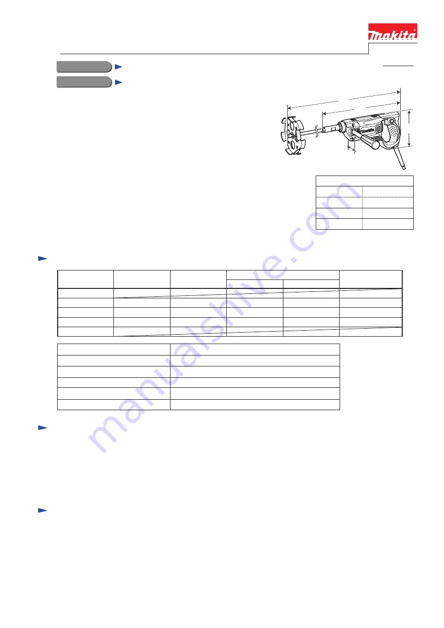
Dimensions: mm (")
Width (W)
Height (H)
Length 1 (L1)
356 (14)
Length 2 (L2)
Length 1: without mixing blade
Length 2: with mixing blade
942 (37)
87 (3-7/16)
152 (6)
Note: The standard equipment for the tool shown above may differ by country.
UT1305
Mixer
Model UT1305 has been developed as the double insulation
model to the current grounding type model UT1304.
The main advantages are;
*Rear handle with soft rubber grip, ergonomically designed
for comfortable operation
*Pilot lamp
Shank size of tool holder portion
Double insulation
Net weight: kg (lbs)
Power supply cord: m (ft)
No load speed: min-
1
=rpm.
Max blade diameter: mm (")
1,300
Yes
M12
165
Europe: 4.0 (13.1), Other countries: 2.5 (8.2)
3.2 (7.1)
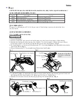
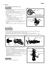
Wrench 13 ............ 1 pc
Wrench 19 ............ 2 pcs
Grip complete ....... 1 pc
Mixing blade 165 ........................ 1 pc
Shaft for Mixing blade 165 ......... 1 pc
Mixing blades 130, 150, 165
Shaft (for 130, 150, 165)
L2
L1
H
W
T
ECHNICAL INFORMATION
Continuous Rating (W)
Voltage (V)
Cycle (Hz)
Input
Output
Max. Output (W)
120
110
850
4.1
850
480
900
50/ 60
3.9
850
480
900
50/ 60
7.5
440
850
50/ 60
220
230
240
Current (A)