background image

Summary of Contents for D 2866 LE 401

Page 1: ......

Page 2: ...iesel engines was taken for granted when this publication was compiled Any repair of components such as injection pump alternator etc ought to be left to our or the manufactur er s service department...

Page 3: ...pump 42 Repairing water pump 41 Removing and attaching expansion tank 45 Removing and installing heat exchanger 46 Cleaning heat exchanger pipe set 48 Raw water pump 49 Lubrication Changing oil filte...

Page 4: ...alling timing case 98 Removing and installing camshaft exchanging camshaft bearing 99 Checking valve timing 101 Crankgear pistons Removing and installing crankshaft 102 Removing and installing piston...

Page 5: ...be ac cidentally started from the bridge by unauthorised persons D The engine must be started and operated by authorised personnel only D When the engine is running do not get too close to revolving c...

Page 6: ...working on the electrical system unplug earth cable from battery first and recon nect it last to avoid short circuits D Observe the manufacturer s instructions for handling batteries Caution Battery...

Page 7: ...ust be free of water D Do not fill up with engine oil above the max notch on the dipstick Do not exceed the engine s maximum permissible operating inclination Non compliance with these instructions ma...

Page 8: ...in contact with engine oil Wash yourself thoroughly with soap and water A nailbrush is an effective aid Special hand cleaning agents facilitate cleaning soiled hands Do not use petrol Diesel fuel gas...

Page 9: ...s good compression values and the following operating values measured and recorded and have not changed significantly since commissioning D Charge air pressure D Exhaust gas temperature D Coolant and...

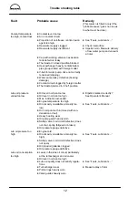
Page 10: ...obable causes by asking specific questions examining and eliminating these causes one by one with the aid of the table and your own experience This helps to reduce repairs to those necessary and count...

Page 11: ...art D Fuel tank empty D Fuel valve shut D Cut off solenoid in STOP position D Air in fuel system D Fuel lines leaky ruptured clogged D Fuel filter prefilter clogged D Suction height of fuel delivery p...

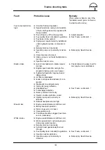
Page 12: ...t system and propeller with foreign matter D Propeller consumes too much power nominal speed is not reached D Propeller consumes too much power engine runs in the breakaway range D Flow of water on to...

Page 13: ...ube oil pressure varies too low D Oil level in oil pan too low D Oil level in oil pan too high D Max inclination exceeded D Engine temperature too high D Oil viscosity unsuitable viscosity too low D O...

Page 14: ...h power D Sudden full load after long low load or idling periods D Air filter contaminated D Leaks in air pipes downstream of com pressor D Diaphragm in wastegate leaky D Intercooler leaky defective D...

Page 15: ...clutch D Unsuitable engine gearbox mounts D Elastic mounts unequally loaded height adjustment D Propeller shaft unbalanced Engine knocks D Engine in cold running phase D Delivery start set incorrectly...

Page 16: ...or check lamp does not come on when engine is stationary and starter switch is switched on D Alternator check lamp brightly ilumi nated when engine is running D Alternator check lamp brightly ilumi na...

Page 17: ...Engine views D 2866 LE401 16...

Page 18: ...Engine views D 2866 LE401 17...

Page 19: ...Cross section of engine 18...

Page 20: ...Longitudinal section 19...

Page 21: ...gine lubrication system 20 1 2033 2 3 4 5 9 6 7 8 10 1 Oil suction pipe 6 Bypass valve 2 Distributor pipe 7 Oil filter 3 Oil spray nozzle 8 Turbocharger 4 Oil pump 9 Oil cooler 5 Oil pressure relief v...

Page 22: ...Schematic diagram of fuel system 21 1 Fuel tank 6 Fuel injection pump 2 Fuel prefilter 7 Overflow valve 3 Fuel delivery pump 8 Fuel injector 4 Fuel filter 9 Suction pipe 5 Bleed screw 10 Return pipe...

Page 23: ...er underpressure valve 2 Water pump impeller 11 Coolant filler neck 3 Engine oil cooler 12 Heating lead and return line 4 Crankcase 13 Measuring point for cooling water temperature 5 Exhaust manifold...

Page 24: ...ntral hexagon bolt is located on the front side of the crankshaft pulley Figs 3 and 4 There is another scale engraved on the flywheel which can be read through an inspection hole in the flywheel housi...

Page 25: ...the lug 3 fits in the groove 4 Tighten the knurled nut 5 by hand Connect up power supply of light signal transmitter red terminal Turn engine by hand so that piston in cylinder no 1 in the compression...

Page 26: ...vailable good measurement results can also be achieved with a plug in sleeve The sleeve is to be made of aluminium or steel Set engine to start of delivery as described above Insert the sleeve into th...

Page 27: ...angle for delivery start Remove cylinder head cover from cylinder no 6 flywheel end When the values of this cylinder are in crossover the piston in cylinder no 1 is at ignition TDC Remove screw plug...

Page 28: ...ove bracket from the injection pump 19 mm Fig 3 Remove the mounting bolts from the injection pump flange 17 mm Note For reasons of space the mounting bolt be tween the injection pump and the crankcase...

Page 29: ...t Take cylinder head cover off cylinder no 6 fly wheel end When the cylinders are in crossover the piston of cylinder no 1 is at TDC at the end of the compression stroke Fig 7 Check whether the inject...

Page 30: ...itial torque of 5 Nm to all mounting bolts on the gear through the inspection hole Two com plete engine turns are necessary for this operation Now tighten all mounting bolts to 30 Nm Check delivery st...

Page 31: ...emoving fuel injectors Fig 1 Remove leakage fuel return lines Fig 2 Remove injection lines Fig 3 Remove pressure screw from fuel injector using a pin spanner Fig 4 Bolt inertia puller on to fuel injec...

Page 32: ...k and repair injector Installing fuel injectors Fig 6 Apply Never Seeze to contact areas of injector Screw in injector with new seal Fig 7 Screw in injector with new seal Screw on union nut and tighte...

Page 33: ...nsert a differ ent shim If the pressure is too low insert thicker shims if it is too high insert thinner shims 7 The initial tension of the compression spring 6 de creases if a high number of operatin...

Page 34: ...erior of injection body 1 with a small wooden stick and petrol or Diesel fuel Clean nozzle needle 2 with a clean cloth Note To prevent corrosion do not touch lapped faces of nozzle needle with the fin...

Page 35: ...ightening it to the specified torque Check injector on the manual test stand Ensure that the edge type filter is correctly seated in the injector body Fig 9 A dislocated sieve bar filter throttles and...

Page 36: ...o catch fuel that may emerge Fig 2 Wash out filter housing and gauze filter in clean Diesel fuel and blow them out with compressed air Reassemble fuel prefilter using new seal Fig 3 Actuate plunger of...

Page 37: ...and re move cartridge by hand Fit a new seal Lightly coat seal on the filter cartridge with fuel Screw on filter cartridge and firmly tighten it by hand Bleeding fuel system Fig 3 Open bleed screws at...

Page 38: ...ner and dispose of it in accordance with local regulations Fig 1 Remove cap arrow from filler neck on the coolant expansion tank Open drain plugs Fig 2 Open drain plug in the oil cooler housing Use a...

Page 39: ...eration Ensure that the ratio of water to anti freeze is cor rect Figs 5 and 6 D Remove cap large cap D Set heating if fitted to full output open all shut off valves open bleeders if fitted D Unscrew...

Page 40: ...Check the function of the thermostat as follows D Hang thermostat in a pot filled with water D Heat water D Use suitable thermometer to ascertain the opening start and compare it with the set point v...

Page 41: ...e disassembly and pull off water pump hub with a stable three arm puller Fig 1 Remove the mounting bolts from the cooling water elbow 13 mm Fig 2 Remove mounting bolts from water pump 13 mm and take o...

Page 42: ...peller off the shaft using a suitable man drel For this purpose align water pump housing horizontally on a stable support The picture shows an assembly device for this If such a device is not availabl...

Page 43: ...bearing shaft For this purpose align water pump housing hori zontally on a stable support Fig 6 Refit circlip Fig 7 Press in new mechanical seal with press fitting sleeve special tool see page 127 ite...

Page 44: ...face of the impeller is flush with the front face of the bearing shaft Check the gap dimension with the feeler gauge The impeller must be easy to turn and must not contact the water pump housing Fig...

Page 45: ...er pump can be attributed to unsuit able coolants Only the antcorrosion and antifreeze agents expressly approved by MAN Nutzfahrzeuge AG as per MAN norm 324 see brochure Fuels Lubricants Coolants for...

Page 46: ...om bleeder line Remove coolant level sensor Figs 2 and 3 Remove the mounting bolts from the brackets of the expansion tank 13 mm and 19 mm Fig 4 Remove nut 13 mm from the front side of the ex pansion...

Page 47: ...ecting pipe from the intercooler is fastened to the heat exchanger by means of a plug connection To detach it remove pressure flange 10 mm Remove pipe clamps from the raw water pipe and pull out pipe...

Page 48: ...ve both covers 13 mm Fig 2 Take off cover At the flywheel end of the heat exchanger the col lar of the pipe cluster arrow is visible Fig 3 Carefully knock out pipe cluster from the opposite end using...

Page 49: ...t in a suitable container made of synthetic material such as PE PP PVC GRP etc D Fill container with undiluted genuine pickling liquid at room temperature engine pickling fluid RB 06 until the pipe se...

Page 50: ...mps have been in use for improved cooling However the assembly steps are the same in principle Fig 1 Remove the mounting bolts from the suction and compression necks 13 mm Fig 2 Remove the nuts from t...

Page 51: ...ion neck using a screwdriver Fig 3 Pull out impeller together with the cam using a pair of pliers Exchange worn or damaged impeller together with the wearing parts repair kit observe the direction of...

Page 52: ...lter bowl 17 mm Fig 3 Take off filter bowl and clean it internally Insert new filter element and fit filter bowl with new seals Observe tightening torque for mounting bolt see Engineering S Data S Set...

Page 53: ...emove the mounting bolts from the oil cooler housing 17 mm Note Do not remove the four 13 mm mounting bolts They keep the oil cooler in place Fig 2 Take off oil cooler housing together with oil cooler...

Page 54: ...Note Depending on the oil pan variants various versions are possible The pictures show a tandem oil pump with pipes The work is fundamentally the same for all versions Measure backlash between oil pum...

Page 55: ...tandem pumps first remove the 2nd pump with intermediate shaft connection sleeves and circlips Disassembling and assembling oil pump Fig 6 Clamp oil pump in a vice fitted with soft jaws Re move oil p...

Page 56: ...drive gear on the shaft and press it into place Thereby support opposite shaft end Pres sing force see Engineering S Data S Setting va lues Checking axial play of the pump gears Fig 9 Position dial ga...

Page 57: ...it the oil intake lines with seals and the oil re turn lines without seals so that they are free of tension 13 mm Screw on pressure relief valve without seal 13 mm Before mounting the oil pan turn ove...

Page 58: ...the event of repair work Checking oil spray nozzle valve Fig 3 Use a piece of wire to check whether the valve piston is easy to move For opening pressures see Engineering S Data S Setting values Inst...

Page 59: ...vice 13 mm and the deliv ery start pointer 17 mm Fig 3 Loosen mounting bolts on vibration damper 24 mm Note Owing to the high tightening torque a rein forced socket in conjunction with a 1 2 tool is r...

Page 60: ...aft seal Fig 6 To remove the race a puller special tool see page 127 item 13 is necessary Fig 7 Pull off race Fig 8 Special tools are required for installing the race see page 127 item 15 Clean inner...

Page 61: ...ace using collar nut and pressing plate and in Fig 8 until pressing sleeve stops on the adapter Fig 10 As spare parts the cover and shaft seal are deliv ered only as a complete assembly in order to en...

Page 62: ...ing bolts 24 mm to specified torque Note Owing to the high tightening torque a rein forced socket in conjunction with a 1 2 tool is required Fig 14 Screw on delivery start indicator and V belt pulleys...

Page 63: ...m by two guide pins special tool see page 127 item 16 Remove all bolts Fig 3 Pull off flywheel using a flat metal bar and two bolts M12 x 1 5 Do not tilt it so that it jams Caution The flywheel is hea...

Page 64: ...gear to specified torque see Engineering S Data S Setting values Changing starter gear ring Fig 6 Remove flywheel Drill a hole in starter gear ring and snap it using a chisel Caution Take care not to...

Page 65: ...3 Drive in seal with mandrel special tool see page 127 item 12 until flush The pressing mandrel consists of two parts Observe remarks and installation notes on page 66 Note The pictures show the inst...

Page 66: ...al fragments Caution Do not damage flywheel Do not use a chisel Fig 2 Insert the new bearing race into the pressing man drel special tool see page 127 item 14 so that for the subsequent assembly the i...

Page 67: ...eals Even the slightest damage to the seal would result in leaks The sealing lip and the race of the flywheel must not be coated with oil or any other lubricants When installing a new seal always repl...

Page 68: ...nt dirt and foreign matter from penetrating into the system Removing intake manifold Fig 1 Remove hose connection from LDA Fig 2 Remove the mounting bolts from the intake pipe 13 mm Fig 3 Take off int...

Page 69: ...anifold Fig 1 Remove the mounting bolts from the exhaust pipe 17 mm Fig 2 Caution The exhaust pipe is heavy Before removing all mounting bolts it is advisable to replace two bolts with self made threa...

Page 70: ...5 6 Removing and installing exhaust manifold 69 Fig 5 Fit exhaust pipe with new seals Fig 6 Tighten the mounting bolts to specified torque see Engineering S Data S Setting values 3498 3499...

Page 71: ...de of the com pressor Check outside of turbocharger for oil traces Oil consumption caused directly by turbocharger depends on the bearing wear and results in relatively early mechanical damage If engi...

Page 72: ...is installed The engine oil used is unsuitable see publication Fuels Lubricants Coolants for Industrial and Marine Diesel Engines The engine is being run on impermissibly steep inclines The crankcase...

Page 73: ...ow high must the charge air pressure be A general set point value for the charge air pressure cannot be given Values ascertained on the test bed ought not to be used for comparison as the respective i...

Page 74: ...rank case breather Remove the air intake funnel and the connection from the compressor to the charge air elbow Remove the hose from the wastegate Fig 2 Remove oil supply and return lines 17 mm Fig 3 R...

Page 75: ...ss when putting the turbocharger aside to prevent dirt and foreign matter from penetrating into the inte rior of the turbocharger Installing turbocharger Fig 7 The turbocharger is assembled in reverse...

Page 76: ...otor shaft against dial gauge Read and note down value Push rotor in opposite direction Read and note down value The difference between the two is the axial play Change turbocharger if axial play is e...

Page 77: ...es arrow Their task is to limit the charge air pressure to a precisely defined value Manipulation or modification of the setting is not permitted Fig 2 The waste gates are maintenance free Remove the...

Page 78: ...intercooler con necting elbow leading to the intake pipe 13 mm Note For reasons of space one bolt between the expansion tank and the elbow can be reached only with a 1 4 socket and an ex tension Take...

Page 79: ...stalling intercooler 78 Disassembling and cleaning intercooler Fig 5 Remove charge air elbow 13 mm Fig 6 Clean the fins on the intercooler of oil and resi dues using a steam jet cleaner Do not damage...

Page 80: ...ust pipes need not be detached for removing the cylinder head Fig 1 Remove the injection nozzles see page 30 Take off the cylinder head covers 13 mm Fig 2 Remove the coolant bleed pipe Fig 3 Back off...

Page 81: ...move those intake and exhaust pipe bolts which are adjacent to the respective cylinder head This will reduce the tension on the cylinder head and the head can be taken off more easily Fig 8 Take off c...

Page 82: ...before in serting them and apply Optimoly WhiteT assem bly paste to the contact face of the bolt head Fig 12 Tighten bolts by angle Observe order of tightening and specified tightening method and see...

Page 83: ...slightly Align rocker arms to valves Tighten the mounting bolts to the specified torque Note Use only M10x70 mounting bolts property class 10 9 Fig 14 Fit new seals between the cylinder head and the...

Page 84: ...changing the cylinder head gasket Tighten cylinder head bolts while the engine is cold i e the crankcase is warm to the touch or colder Before inserting the cylinder head bolts apply engine oil to the...

Page 85: ...es overlap Note As far as possible turn engine only in direc tion of rotation anti clockwise as seen when looking at the flywheel in order to prevent the direction of rotation of the raw water pump im...

Page 86: ...moved with slight resistance Tighten lock nut to the specified torque see Engineering S Data S Setting values using screw driver to prevent adjusting screw from turning Check clearance again Refit cyl...

Page 87: ...shaft Note If the rocker arm bearing bushes have to be exchanged ready to install new or recondi tioned rocker arms are to be used Fig 4 Before fitting the rocker arms 1 to the rocker arm shafts and...

Page 88: ...Note If a valve fixture is available in the workshop the procedure described may also be carried out on the said fixture Use valve assembly lever to press valve spring retainer and spring downwards an...

Page 89: ...ways be lapped until an even valve seat has been achieved Machine valve seat insert if necessary Turn cylinder head over and insert valve spring washers Screw off valve assembly lever Figs 6 and 7 Pla...

Page 90: ...n the inlet valve only 3 Washer 4 Outer valve spring 5 Washer 6 Inner valve spring 7 Spring retainer 8 Tapered element Measuring valve recess Figs 10 and 11 Place dial gauge holder and dial gauge on c...

Page 91: ...d using pressing mandrel and spacer sleeve special tool Fig 2 The valve guides vary only in length 1 Inlet long guide 2 Exhaust short guide 3 Press in depth see publication Engineering S Data S Settin...

Page 92: ...valve seat machining tool valve seat lathe to cut an approx 3 4 mm wide groove in the valve seat insert Insert internal puller into the groove and tighten it Fig 2 Note To avoid damage to the cylinde...

Page 93: ...When the valve seat inserts have been changed the valve seats must be reworked 3534 Notes D After temperature equalization machine valve seats D After machining clean cylinder head and check for leaks...

Page 94: ...ns connection 14 Magnetic flange with coil 15 Guide pipe 16 Slewing arm Fig 2 Select suitable guide mandrel screw it in with a spanner 12 mm and tighten it Note For extreme precision work the guide ma...

Page 95: ...carbide cutting edge may break Fig 6 Once the valve seat has been expertly machined reduce the working pressure of the tool by 2 3 rev olutions without feed motion During these revolutions turn the fe...

Page 96: ...e valve retrusion If new valves and seat inserts are used increase the depth of the seat bore in the cylinder head ac cording to the amount of material removed from the cylinder head interface Fig 9 T...

Page 97: ...Fig 3 The valve seat must have a faultless closed grind ing pattern 2 The grinding pattern width is correct if the valve seat insert is in order 1 Valve tapered area 2 Valve seat Fig 4 1 Valve seat i...

Page 98: ...e same time holding adjusting lever of injection pump in stop position Connect up compression recorder with test con nection to the next cylinder and check all cylinders as described above Fig 3 Depen...

Page 99: ...ff the timing case and fit a new one Fig 3 Check the contact washer on the camshaft for wear if necessary fitting a new one Fig 4 Stick new gasket to timing case using grease Fit flywheel housing Chec...

Page 100: ...or this reason the en gine must be placed on a dolly Fig 1 Remove raw water pump with drive system 13 mm 19 mm Fig 2 Remove angle drive cover 17 mm and raw wa ter pump drive gear from the camshaft 17...

Page 101: ...ods and the crankshaft before remov ing camshaft bearings Fig 5 Remove camshaft bearing bushes with suitable mandrel and drive in new bushes Ensure that the oil supply bores are in correct position In...

Page 102: ...nded Fig 1 Remove cylinder head cover from 1st cylinder Carefully set exhaust valve for 1st cylinder Turn engine until the valves of the 1st cylinder are in crossover Turn engine back to approx 50_ be...

Page 103: ...Fig 2 Loosen and remove mounting bolts from crank shaft bearing caps in stages from the inside out Take off bearing caps and arrange them in order of installation Take the bearing shell halves out of...

Page 104: ...l to the running surfaces on the bearing shells and install crankcase ensuring that the markings on the crankshaft and camshaft gears coincide Fig 8 Check whether the bearing cap bolts have ex ceeded...

Page 105: ...ssible axial play is exceeded replace main bearing shells complete Fig 11 Measure connecting rod bearing insert pistons with connecting rod Coat connecting rod bearing shells with oil and pull connect...

Page 106: ...d with the connecting rod big ends arrange them in corresponding order Fig 3 Remove combustion residues oil carbon from top cylinder edge using a piece of hard wood Caution Do not damage cylinder line...

Page 107: ...the corresponding repair stage Fig 6 Insert bearing shells into the connecting rods or connecting rod bearing caps Important The rod shell has a red or yellow mark on the side The top coat must not b...

Page 108: ...ges to specified value Tighten finally by angle For tightening torques and reusability of bolts see Engineering S Data S Setting values Fig 11 Slowly turn engine over Connecting rods and oil spray noz...

Page 109: ...f and lay it aside Measure connecting rod big end bore basic bore Fig 3 Insert new connecting rod bearing and fit cap Tighten bolts to specified torque Measure bearing bores with inside micrometer in...

Page 110: ...ting rod to see whether the piston pin bore is parallel or twisted relative to the bearing shell bore Change connecting rod if deviations exceed the tolerance range Fig 6 Fit piston to connecting rod...

Page 111: ...o piston diameter Fig 3 Apply piston ring pliers at piston ring gap and unclip piston rings from piston ring grooves Note Owing to the hose type spring the oil scraper ring has a higher tangential ten...

Page 112: ...Checking piston ring axial clearance Fig 7 Use feeler gauge to ascertain the piston ring clear ance at several points in each groove For this purpose the piston ring is to be fully pressed into the p...

Page 113: ...e so that it can be reinstalled in the same position if re used Insert cylinder liner extractor device into cylinder liner taking care not to damage the oil spray nozzle Put support on extractor spind...

Page 114: ...Position press on measuring plate 1 with turned collar facing the liner using 2 fitting sleeves to centre plate Tighten 4 bolts 2 improvised collar bolt 51 90020 0270 length shortened to 90 mm on the...

Page 115: ...e felt in this oper ation the O rings are no longer in their proper place Reposition O rings and insert cylinder liner again Note No grease or sealing agents of any kind must be used for installing cy...

Page 116: ...piston to be measured to TDC Apply dial gauge in holder to crankcase sealing face Set dial gauge to 0 Fig 2 Carefully slew dial gauge holder round lifting the dial gauge tip as you do so Lower dial g...

Page 117: ...rush dipped in fuel and regrease it 4392 Check flywheel gear ring for wear and damage Turn over engine by hand once paying particular attention to the positions at which the engine finally stops i e w...

Page 118: ...gauge arm moves upwards A false reading will be obtained if you continue to apply pressure after the spring has disengaged Fig 4 Taking tension reading D The tension is shown where the top of the gau...

Page 119: ...Figs 5 and 6 Remove the mounting bolts from both the alterna tor and the tensioning device Fig 7 D Loosen lock nut D Turn adjusting nut until the V belts are cor rectly tensioned D Retighten lock nut...

Page 120: ...plied to the probe the signal appears for approx 2 seconds to signalise that the probe is ready for operation If this signal does not appear the probe must be checked It is not possible to carry out a...

Page 121: ...s the liquid is heated Measure the resistance and compare it with the calibrated curves _F 1 8_C 32 Curve 1 Temperature transmitter for 1 electrical instrument Curve 2 Temperature transmitter for 2 el...

Page 122: ...sistance and compare it with the calibrated curves Curve 1 Pressure transmitter for 1 electrical instrument Curve 2 Pressure transmitter for 2 electrical instruments Pressure transmitter for 1 electri...

Page 123: ...600 mV _C If the exhaust gas temperature transmitter is to be checked the exhaust gas temperature must be measu red with a second independent instrument Disconnect the gauge from the transmitter Measu...

Page 124: ...123 Special tools...

Page 125: ...Special tools 124 2 3 4 5 6 7 9 1 8 6 1 6 2 6 3...

Page 126: ...nner 83 09195 0002 5 Spanner for nuts on injection lines 17 mm 80 99603 0025 6 Socket spanner set for fuel injector 6 2 4 groove 80 99603 0049 6 3 4 groove with fixing screw 80 99603 0121 6 4 open 3 g...

Page 127: ...Special tools 126 10 11 16 14 14 1 12 13 18 18 1 17 12 1 12 2 15 5 15 4 15 1 15 1 15 2 15 3 15 3 15 6 15 7 15...

Page 128: ...80 99601 0076 14 Pressing tool for bearing race on flywheel in conjunction with handle 14 1 80 99617 0017 14 1 Handle 80 99617 0129 15 Special tools for front crankshaft seal 80 99606 6011 Components...

Page 129: ...Special tools 128 21 22 23 25 25 2 24 25 1 26 27 1 27 2 27 20 1 19 2 19 1 20 2 19 20...

Page 130: ...conjunction with 20 1 80 99616 0003 21 Piston ring tightener 80 99613 0035 22 Piston ring tightening sleeve 80 99604 0134 23 Tightening angle gauge 80 99605 0010 24 Piston ring pliers 83 09144 6090 2...

Page 131: ...Special tools 130 29 28 30...

Page 132: ...signation Item number 28 Valve assembly lever 80 99606 0031 29 Dial gauge holder for measuring valve retrusion and piston protrusion 90 99605 0172 30 Pressure gauge accessories for charge air pressure...

Page 133: ...ion consisting of 1 Dial gauge 08 71000 1205 2 Tracer pin for dial gauge 80 99605 0197 3 Dial gauge holder 80 99605 0179 4 Contact pin 80 99605 0180 5 Dial gauge holder 80 99605 6006 6 Dial gauge hold...

Page 134: ...Special tools 133 2843 Pressing mandrel for cap dia 50 1 mm Pressing mandrel for cap dia 62 1 mm...

Page 135: ...Special tools 134 Special tools for water pump repair for local manufacture Material steel as available Support ring for pressing out the water pump bearing 68 56 90...

Page 136: ...st pipe Installing 68 Expansion tank 45 F Faults and causes 9 15 Flywheel Removing and installing 62 Fuel filter Changing cartridge 36 Fuel prefilter Cleaning 35 Fuel system diagram 21 H Heat exchange...

Page 137: ...r ring 63 T Timing case Removing and installing 98 Transmitter Coolant temperature 120 Exhaust gas temperature 122 Oil pressure 121 Thermostat Removing and installing 39 Turbocharger Axial play 75 Ins...

Page 138: ......

Reviews: