Summary of Contents for FDMC
Page 1: ......
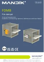
The Mandik FDMC General Information Manual is a comprehensive guide that includes everything you need to know about operating your Mandik FDMC product efficiently. You can easily download this manual for free from 88.208.23.73:8080 and have access to all the essential information you need at your fingertips.
Page 1: ......