


Summary of Contents for FDML
Page 1: ......
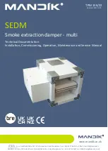
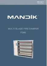
Introducing Mandik FDML, a comprehensive user manual designed to simplify your product experience. This downloadable manual provides clear instructions and troubleshooting tips to ensure seamless usage. Get your free Mandik FDML manual now at 88.208.23.73:8080, enhancing your understanding and maximizing the potential of your product.
Page 1: ......