MANDÍK, a. s. • Dobříšská 550 • 267 24 Hostomice • Czech Republic • Tel.: +420 311 706 742 • E-Mail: mandik@mandik.cz
Manufacturer
MANDIK UK Ltd • 130 Aztec West • Bristol BS32 4UB • United Kingdom • Tel.: +44 117 4526376 • E-Mail: help@mandik.co.uk
Authorized representative
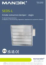
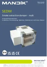
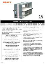
SEDM-L
Smoke extraction damper - multi
Technical Documentation
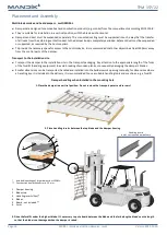
Installation, Commissioning, Operation, Maintenance and Service Manual
TPM 157/22
Version 2022-12-20