background image

Part Number 020002365 08/25/2015

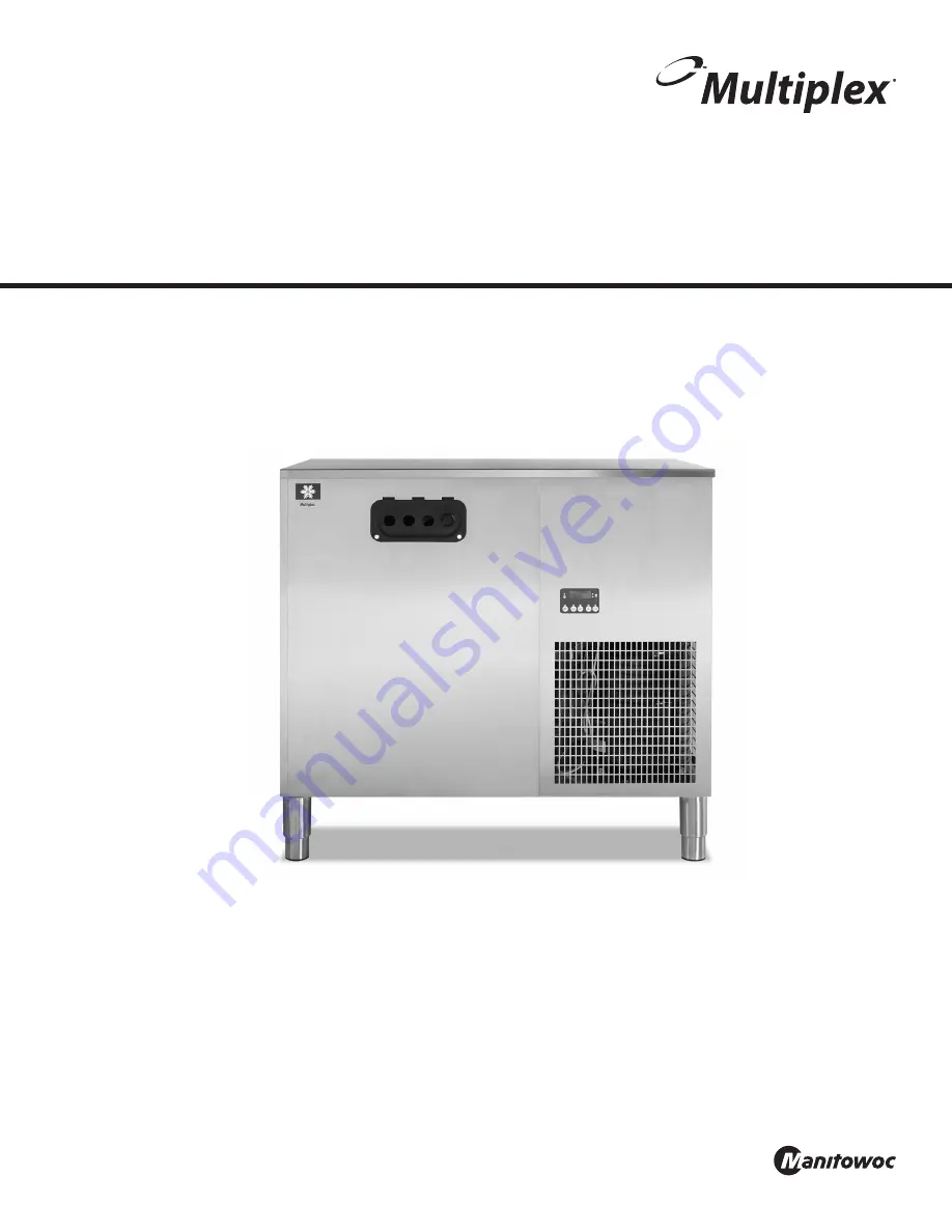
Post Mix Soda and Super-Chil™

Refrigeration Unit with Electronic Control

Installation, Operation and Maintenance Manual

This manual is updated as new information and models are released. Visit our website fo rthe latest manual.  

www.manitowocbeverage.com/us

Summary of Contents for Multiplex 42 MR04

Page 1: ...Soda and Super Chil Refrigeration Unit with Electronic Control Installation Operation and Maintenance Manual This manual is updated as new information and models are released Visit our website fo rthe latest manual www manitowocbeverage com us ...

Page 2: ...ential for maximum performance and trouble free operation of your Multiplex equipment Read and understand this manual It contains valuable care and maintenance information If you encounter problems not covered by this manual do not proceed contact Manitowoc Beverage Equipment We will be happy to provide assistance Importan Routine adjustments and maintenance procedures outlined in this manual are ...

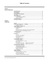
Page 3: ...r Post Mix Refrigeration Units 11 Installer Instructions 12 Preparation 12 Electrical 12 General 12 Minimum Circuit Ampacity 12 Electrical Requirements 12 Specifications 12 Grounding Instructions 13 Plumbing Water Supply 14 Plumbing Potable Water 14 Plumbing Requirements General 14 Water Supply 14 Plumbing Circuit Diagrams Models 42 44 and SC1000 15 Plumbing Circuit Diagrams Models 50 and SC2000 1...

Page 4: ...x Works 32 Start Up 32 Placing Equipment in Operation 32 Placing the Syrup System in Operation 32 Sequence of Operation 33 Electronic Control 33 Equipment Setup and Close Procedure 36 Equipment Setup Procedure 36 Equipment Close Procedure 36 Section 4 Maintenance Maintenance Schedule 39 Periodic Maintenance For Equipment Listed By Major Components 39 Cleaning and Sanitizing the Dispensing Valves a...

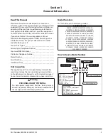
Page 5: ... Immediately report any damage that occurred during transportation to the delivery carrier Request a written inspection report from a claims inspector to document any necessary claim nWarning PERSONAL INJURY POTENTIAL Do not operate equipment that has been misused abused neglected damaged or altered modified from that of original manufactured specifications Model Numbers This manual covers the fol...

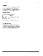
Page 6: ...STALLATIONS nWarning This unit is for use on vessels over 66 ft 20 m in length This unit must not be installed in the engine space of a gasoline powered ship NOTE This unit must be secured to the vessel during installation Models with part numbers beginning with the letters TS are NOT marine listed OUTDOOR APPLICATIONS TS Multiplex Beverage Recirculating units are approved and listed by Underwrite...

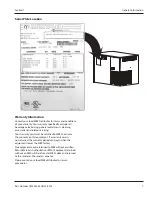
Page 7: ...ies and related servicing Your warranty card must be returned to MBE to activate the warranty on this equipment If a warranty card is not returned the warranty period can begin when the equipment leaves the MBE factory No equipment may be returned to MBE without a written Return Materials Authorization RMA Equipment returned without an RMA will be refused at MBE s dock and returned to the sender a...

Page 8: ...8 Part Number 020002365 08 25 2015 General Information Section 1 THIS PAGE INTENTIONALLY LEFT BLANK ...

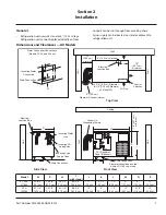
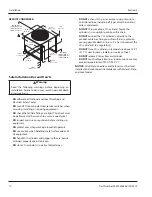
Page 9: ...de View P Wall Electrical Junction Box Incoming Water Line Incoming CO2 Supply Line Incoming Syrup Supply Lines Drain Connection W Ceiling Wall 18 45 7 cm minimum I H CO2 Regulator Panel Optional N Drain Connection Floor drain should be located within 6 ft 183 cm of unit Wall Conduit to Dispensing Towers D Water Condenser Connections Models 42 44 and 50 only K Incoming Water Connection Drain Conne...

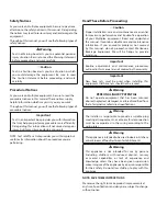
Page 10: ...protect eyes when working around refrigerants DO use caution when handling metal surface edges of all equipment DO handle CO2 cylinders and gauges with care Secure cylinders properly against abrasion DO store CO2 cylinder s in well ventilated areas DO NOT exhaust CO2 gas example syrup pump into an enclosed area including all types of walk in coolers cellars and closets DO NOT throw or drop a CO2 c...

Page 11: ... level is above 70db nWarning Carbon Dioxide CO2 displaces oxygen Exposure to a high concentration of CO2 gas causes tremors which are followed rapidly by loss of consciousness and suffocation If a CO2 gas leak is suspected particularly in a small area immediately ventilate the area before repairing the leak CO2 lines and pumps must not be installed in an enclosed space An enclosed space can be a ...

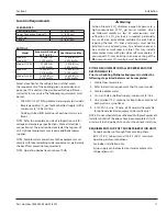
Page 12: ...t This equipment is rated for indoor use only It will not operate in sub freezing temperature In a situation when temperatures drop below freezing the equipment must be turned off immediately and properly winterized Contact the manufacturer for winterization process Electrical GENERAL nWarning All wiring must conform to local state and national codes MINIMUM CIRCUIT AMPACITY The minimum circuit am...

Page 13: ...y grounded Do not modify the plug provided with the appliance if it will not fit the outlet Have a proper outlet installed by a qualified electrician nWarning When using electric appliances basic precautions must always be followed including the following a Read all the instructions before using the appliance b To reduce the risk of injury close supervision is necessary when an appliance is used n...

Page 14: ...70 psi 4 8 bar 482633 0096 Pascals a water regulator will be required 2 Locate the drain hose bracket and two screws provided in the installation kit Attach the drain hose to the water bath overflow tube located on the bottom of the refrigeration unit 3 Connect the water manifold supply line located on the bulkhead panel in the motor compartment to the main water supply The main water supply shut ...

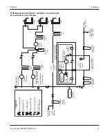
Page 15: ...rculator Pump Tower Tower Tower Optional Constant Water Pressure Booster Module Booster Tank High Pressure Switch H L High Pressure Gauge Low Pressure Switch Constant Pressure Booster Pump Pump Pressure Regulator 55 psi 3 8 bar Low Pressure Gauge Fine Filters optional Coarse Filter optional To Optional Water Cooled Condenser Primary Water Supply Booster Module Replacement Line Electric Solenoid Va...

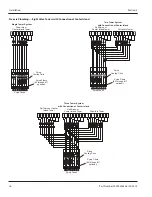
Page 16: ... 8 7 6 1 2 3 4 5 8 7 6 1 2 3 4 5 8 7 6 A 5 A 4 A 3 A 2 A 1 W 7 A 8 A 6 1 2 3 4 5 7 8 6 A 5 A 4 A 3 A 2 A 1 W 7 A 8 A 6 1 2 3 4 5 7 8 Single Tower System Two Tower System with Connection at Center Island Three Tower System with Connection at Center Island Self Serve or Center Island Tower Drive thru Tower Self Serve or Center Island Tower Drive thru Tower Self Serve or Center Island Tower Syrup Coo...

Page 17: ...wer System with Connection at Unit Three Tower System with Connection at Unit Self Serve or Center Island Tower Drive thru Tower Self Serve or Center Island Tower Drive thru Tower Self Serve or Center Island Tower optional Pressurized Filtered Water Supply Pressurized Filtered Water Supply Pressurized Filtered Water Supply Drive thru or Center Island Tower Primary Carbonator Pump Circulator Pump W...

Page 18: ...h Constant Pressure Booster Pump Pump Low Pressure Gauge Fine Filters Coarse Filter To Water Cooled Condenser Primary Water Supply Booster Module Replacement Line Legend Electric Solenoid Valve Manual Ball Valve 3 way Ball Valve Pressure Relief Valve Check Valve Ball Type Check Valve Vent to Atmosphere Carbonator Pump A Pump Pump Pump Carbonator Pump B Cooling Coil Carbonator Tank B Cooling Coil C...

Page 19: ...s Sugar Base Lines Disconnects Optional Air CO 2 Change over Valve Optional CO 2 Change over Valve A B Optional Air Compressor Optional Bulk CO 2 Tank Set at 90 100 psi 6 2 6 9 bar Optional CO 2 Tank A Optional CO 2 Tank B Pressure Switch ON 70 psi 4 8 bar OFF 90 psi 6 2 bar Shake Machine CO 2 Shut off to Carbonator Tank Medium Pressure Regulator Set at 60 psi 4 1 bar Low Pressure Regulator Set at...

Page 20: ... 6 ft 183 cm drain hose 3 Locate any of the optional Kit Assembly for mounting to match the type of mounting required Install the kit as noted in the instructions supplied 4 Record the Model Number Serial Number and date of installation for future reference or to be used when ordering parts UNIT INSTALLATION OVERVIEW 1 Set unit in place 2 Connect the circuit electrically Refer to chart 3 Connect w...

Page 21: ...eration Unit onto the stand Position the unit in the center of the stand Be sure to orientate the drain of the refrigeration unit with the drain access hole of the stand Secure with 5 8 11 x 1 bolts supplied in kit use two 2 bolts diagonally Schedule the plumber and electrician to connect the water supply and electrical service if you have not already done so refer to Electrical Requirements and P...

Page 22: ...ded CO2 gas line and the black incoming water line through the inlet opening on the left side of the refrigeration unit Do not allow any of these lines to rest on the agitator motor or any other surface that may become hot 5 Attach the black water supply line to the water filter or a filtered water supply A 3 8 barb fitting and tab clamp reducer bushing and 3 8 male pipe x 1 2 OD John Guest tube a...

Page 23: ...al equipment component installation instructions for completion if applicable of the beverage system Do not connect the syrup supply at this time 2 Locate the conduit supply lines for the refrigeration unit There are four 4 1 2 1 27 cm carbonated water lines marked in sets for the system Connect the yellow carbonated water supply line 7 to the yellow carbonated water return line A Connect the blue...

Page 24: ... two water lines or use one of the tees supplied to connect the two lines together 6 Insert the conduit supply lines into the left hand opening of the refrigeration unit Connect the John Guest fittings requiring the longest tube from the end of the insulation first Use two tab clamps each per connection It may be necessary to moisten the lines and fittings before inserting the tubing over the barb...

Page 25: ...tion unit to the dispensing station s according to the instructions enclosed with the conduit kit Always route the conduit in a neat and orderly manner 2 Insert the Multipar conduit into the outlet opening on the left hand side of unit Conduit insulation must extend inside of opening in unit for proper operation of equipment Insulated Beverage Conduit NOTE Multipar conduit is color coded for easy ...

Page 26: ...Panel Water Bath Area John Guest Fittings Agitator Motor Carbonator Pump Recirculation Pump Model 42M Does Not Have Second Carbonator Pump Carbonator Tank Model 50 SC2000 Components Control Panel Water Bath Area John Guest Fittings Agitator Motor Carbonator Pump Recirculation Pump Carbonator Tank ...

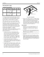
Page 27: ...le tightening the nut with the second wrench If the body turns excessively the piercing seal will be damaged 4 Use proper wrenches to tighten an additional 1 4 turn 90 This final 1 4 turn is necessary to ensure the formation of a leak proof joint Alternately use a torque wrench to tighten the 1 2 coupling to 40 ft lbs and 3 8 fitting to 11 ft lbs 5 Leak check all your connections If you detect any...

Page 28: ...ote condensing units have a 208 230 Volt 50 60 HZ 1 PH fan motor that includes a permanent split capacitor and internal overload protection The electrical wires from the refrigeration unit wire to the condenser The electrical installation must be in accordance with local codes National Electrical Code and regulations 1 Determine a position for installation that will allow access for maintenance an...

Page 29: ...CO2 tank changeover valve handle if applicable toward this regulator 3 Move the air CO2 changeover valve to the CO2 position if applicable 4 Allow the CO2 gas to enter the system 5 Wait for 2 or 3 minutes before turning OFF the CO2 tank valve This will allow the lines to expand under pressure 6 Turn OFF the CO2 tank valve Observe the pressure on the high pressure gauge not the 90 psi 6 2 bar 62052...

Page 30: ...and that the accumulator tank valve is open If the system has an optional Out of Syrup device verify that it is unplugged 6 Verify the pump is running Place the valve on the right side of the pump box in the purge position until all air bubbles have passed through the line Turn the valve back to dispense Plug the Out of Syrup device power cord into an appropriate wall outlet at this time if suppli...

Page 31: ...5 31 Typical System 8 Valve Soda Tower 6 Valve Soda Tower Conduit In Wall BIB Pumps Water Booster Air Compressor Conduit CO2 Panel Multiplex Refrigeration Unit Water Filters BIB Rack Bag In Box BIB Syrup CO2 Tank Section 3 Operation ...

Page 32: ...fer to the instructions on installing the Remote Condenser Verify proper supply power to unit 1 Fill the refrigeration unit water bath tank with water to within 1 2 13 mm of the top of the overflow tube 2 Open the manual water shut off valve to the water cooled condenser if applicable Refer to page 3 3 for control programming sequence 3 Press Comp Agit to begin building an ice bank 4 Ice will begi...

Page 33: ...The compressor and condenser fan will continue to run until ice contacts the ice bank control probe closest to the evaporator When ice contacts the probe the COMP AGIT LED lights constantly and the compressor and condenser fan motor de energize As the ice bank melts the ice bank control probe will lose contact with the ice the LED will flash and the compressor and condenser fan motor will restart ...

Page 34: ...ndicate Water Pressure PROGRAM MODE 2 Add circulation pumps C and or D Press PGM button for 3 seconds Display shows 0001 Press PGM button again in less than 3 seconds Display shows 0002 program mode 2 Wait 3 seconds Display shows 002 Factory default setting ū ū Pressing CIRC A button energizes de energizes pump A ū ū Pressing CIRC B button energizes de energizes pump B Program CIRC C Press CARB A ...

Page 35: ...y will revert back to normal run mode ERC Operation in Mode 5 Circulating motor LED will flash once per second if energy saving PGM mode 5 is enabled The LED will stay constantly ON if energy saving PGM mode 5 is disabled ERC control monitors all carb motors for entering energy savings cycle mode If no carb cycles in 30 minutes no ERC error codes or sensors open shorted and circulating temperature...

Page 36: ...at 35 psi 2 4 bar 3 Observe the control panel to verify that all pressure gauges are set at correct operating pressures 4 Check the syrup tanks to make sure a sufficient number of tanks are connected in series to satisfy business volume 5 Clean syrup inlet and outlet quick disconnects at the same time tanks are replaced Rinse disconnects in clean potable water EQUIPMENT CLOSE PROCEDURE 1 Clean the...

Page 37: ...SS CARB A SWITCH TO SHOW LLC PROBE CA00 NO WATER CARB A MOTOR ON CA01 LOW SENSOR IN WATER MOTOR ON CA11 LOW HIGH SENSOR IN WATER MOTOR OFF REPEAT ABOVE FOR CARB B SWITCH CbXX PRES CIRC A SWITCH TO SHOW WATER LEVEL PROBE CL_1 WATER CL_0 LOW WATER E3 PRESS COMP AGIT SWITCH DISPLAY SHOWS 4 INDICATING ERROR CODES WILL BE DISABLED UNTIL NEXT POWER OFF ON SEQUENCE F000 TEMPERATURE PRESS CARB A SWITCH TO...

Page 38: ... CIRCULATOR SYSTEM TURN OFF AGITATOR AND BOTH CIRCULATORS ONLY IF BOTH CARB A AND CARB B MEET ENERGY SAVING MODE CONDITIONS IF TWO CIRCULATOR SYSTEM AND ONLY ONE CARB SYSTEM MEETS ENERGY SAVING MODE CONDITIONS TURN OFF ONLY THE ONE CIRCULATOR ASSOCIATED WITH THAT CARBSYSTEM LEAVE AGITATOR ON INCREMENT NO CARB CYCLES ELAPSED TIME CARB MOTOR A OR B CYCLE NO CARB CYCLES ELAPSED TIME 30 0 MINUTES ANY ...

Page 39: ...ary Inspect system for air leaks and repair as required Refrigeration unit Every 4 months 3 times per year Clean the refrigeration unit air cooled condenser using a vacuum cleaner or soft bristle brush If equipped with water cooled condenser verify the water discharge temperature is at 105 F 41 C Adjust water modulating valve if necessary Inspect water bath to verify water level is at the top of s...

Page 40: ...with clean water and mild detergent Wipe dry Every 3 months Syrup circuits Sanitize each syrup circuit See Sanitizing Water bath Drain melt ice and clean using detergent and brush rinse with potable water Do not use water over 140 F 60 C Every 6 months Condenser Vacuum fins or use soft bristle brush scrub brush Air compressor filter if equipped Replace Cleaning Equipment and Supplies Recommended c...

Page 41: ... additional circuits You will need the following items to clean and sanitize the Bag in Box BIB beverage system Three 3 clean buckets Plastic brush or soft cloth Mild detergent Unscented bleach 5 Na CL O or Commercial sanitizer Bag In Box bag connector 1 Prepare the following in the buckets Bucket 1 warm not too hot tap water for rinsing Bucket 2 mild detergent and warm not too hot water Bucket 3 ...

Page 42: ...ater Detergent tank mix approved beverage system cleaner with warm water as directed Sanitizing tank mix a solution of unscented bleach 5 Na CL O or commercial sanitizer and warm to hot water Mixture should supply 100 PPM available chlorine 1 4 oz bleach to 1 gallon water 2 Disconnect all product and water lines from product tanks and remove carbonator 3 Locate the Figal syrup tank for the circuit...

Page 43: ...o step 5 If there is discharge proceed to step 6 6 Observe inlet of 2 check for any discharge If there is no discharge 2 check is OK Proceed to step 7 If there is discharge proceed to step 6 7 Shut OFF CO2 supply and relieve pressure from carbonator tank 8 Remove back flow preventer and install new back flow preventer Turn ON CO2 supply and check for leaks 9 Check water supply strainer upstream of...

Page 44: ...44 Part Number 020002365 08 25 2015 Maintenance Section 4 THIS PAGE INTENTIONALLY LEFT BLANK ...

Page 45: ...ectrode or liquid level control Syrup and plain water only dispensing No pressure Out of CO2 Install fresh tank HP regulator out of adjustment Adjust HP regulator to the proper setting Defective HP regulator Check repair replace HP regulator CO2 line pinched kinked or obstructed Check repair replace CO2 line One valve will not dispense anything Is there power to the valve Broken wire or loose conn...

Page 46: ...rrors Error Code Error Cause E1 Low Water Supply Pressure Lower than 5 psi for 5 Seconds E2 Low CO2 Pressure Lower than 10 psi for 5 Seconds E3 Low Water Level Water Bath Must Cover Top of Evaporator Water Level Probe Mounted Too High E4 High Water Bath Temperature Water Bath Temperature Greater Than 45 F E5 High Water Supply Pressure Water Pressure Greater than 75 psi E6 High Refrigeration Temper...

Page 47: ...PRESS CARB A BUTTON TO VERIFY WATER PRESSURE P DISPLAY PRESSURE 15 PSI REPLACE ERC CIRCUIT BOARD 020001985 REPLACE ERC CIRCUIT BOARD 020001985 SUPPLY PRESSURE 15PSI SUPPLY PRESSURE 20PSI REPLACE WATER PRESS TRANSDUCER 020001992 TROUBLESHOOT WATER SUPPLY SYSTEM TO FI LOW WATER PRESSURE CONDITION REPLACE CO2 PRESS TRANSDUCER 020001992 TROUBLESHOOT CO2 SUPPLY SYSTEM TO FI LOW PRESSURE CONDITION PRESS...

Page 48: ...00 F VERIFY TEMP WITH SECOND THERMOMETERIF STILL 45 FREPLACE ERC BOARD VERIFY PRESSURE WITH SECOND PRESS GAUGE VERIFY TEMPERATURE WITH SECOND TEMP GAUGE 020001985 PRESSURE VERIFIED TEMPERATURE VERIFIED VERIFY TEMPERATURE WITH SECOND THERMOMETER TROUBLE SHOOT WATER SUPPLY SYSTEM TO FIX HIGH WATER PRESS REGULATOR BAD NEEDED FIRST CHECK FOR CONDENSER FAILURE OR HOT GAS BYPASS TEMPERATURE VERIFIED GO ...

Page 49: ...E LEAK IN SYSTEM VERIFY ICE BANK PROBE INSTALLED CORRECTLYPLASTIC STEP ON PROBE AWAY FROM EVAP FIX LEAK UN PLUG CARB B CONNECTOR FROM ERC 1 TO VERIFY CONDUCTIVITY OK THEN CHECK FOR PUMP OUTPUT 32 OZ IN LESS THAN 20 SEC E7 ERROR GOES AWAY PUMP GOOD UN PLUG ICE BANK PROBE CONNECTOR 3 FROM ERC BOARD RESET ERROR PUSH CARB A AND OR B BUTTON OFF THEN ON TO RESET COMPRESSOR ON TOO LONGGOTO COMPRESSOR REF...

Page 50: ...50 Part Number 020002365 08 25 2015 Troubleshooting Section 5 THIS PAGE INTENTIONALLY LEFT BLANK ...

Page 51: ...Part Number 020002365 08 25 2015 51 Section 5 Troubleshooting THIS PAGE INTENTIONALLY LEFT BLANK ...

Page 52: ...vement may necessitate change of specifications without notice Part Number 020002365 08 25 2015 Every new piece of Manitowoc Foodservice equipment comes with KitchenCare and you choose the level of service that meets your operational needs from one restaurant to multiple locations StarCare Warranty lifetime service certified OEM parts global parts inventory performance audited ExtraCare CareCode 2...

Reviews: