USER’S MANUAL
POWER OFFICE UPS
800/1000
1. Inspection
The following items are inside the box:
User’s Manual
UPS
Power cord
Remove the Power Office UPS from its packaging and
inspect it for any damages that may have occurred
during shipping. If any damage is discovered, re-pack
the unit and return it to the place of purchase.
2. Placement of UPS
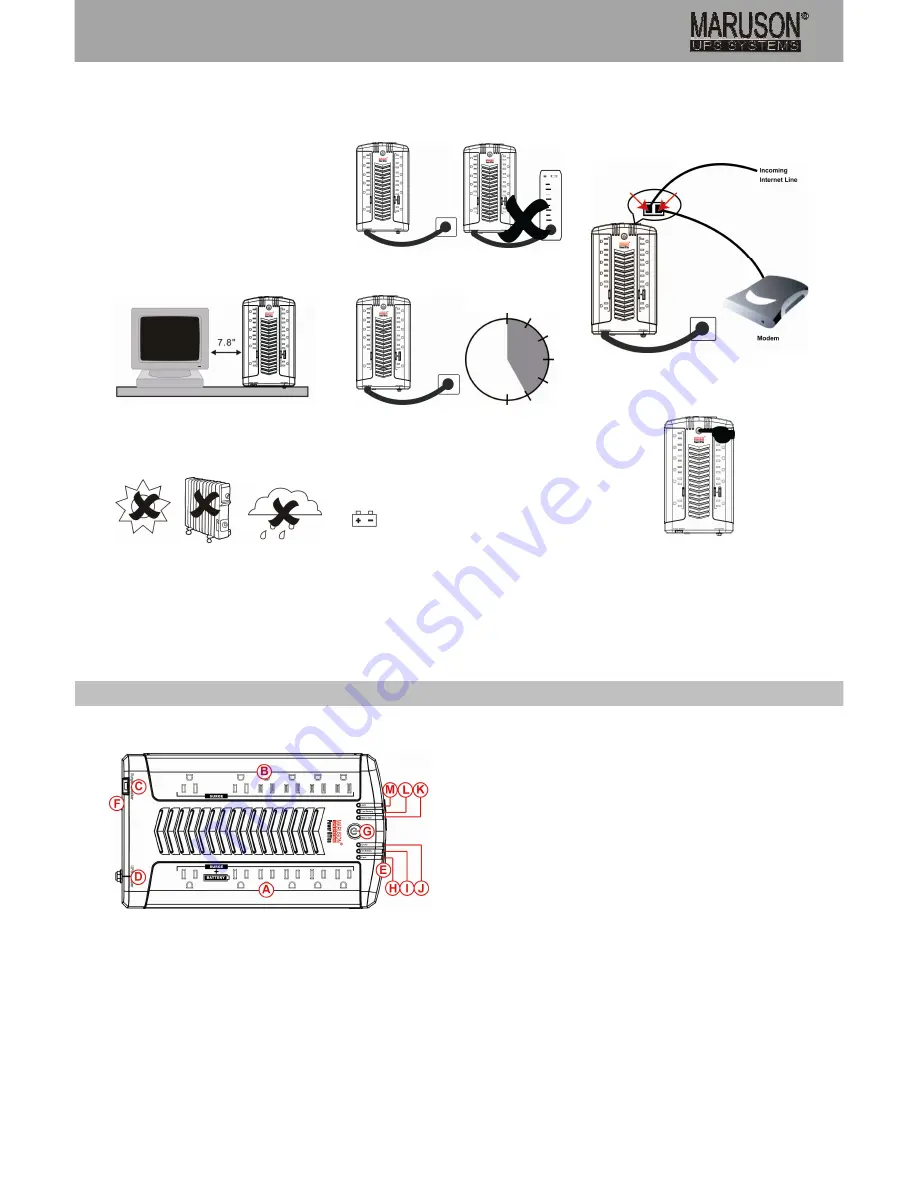
Place the Power Office UPS in a protected area that is
free of excessive dust and provide at least 7.8 inches
(20 cm) clearance on both sides for adequate airflow
around the unit.
Avoid direct sunlight.
Avoid excessive heat.
Avoid excessive humidity or liquids.
Avoid excessive dust.
3. Connect UPS to Utility
Use the power cord that came with your UPS to connect
the UPS directly to the wall outlet.
Do not power the UPS using a surge suppressor or
power strip.
Battery Charging:
The UPS battery charges whenever the UPS is
connected to utility power and typically requires less
than 5 hours to 90% capacity. Operating runtime is
reduced until the battery is fully charged.
4. Connecting Equipment to UPS
Connect the equipment to Battery Power Supplied
outlets.
Battery Power Supplied Outlets (6)
Connect the computer, monitor, and external drive to the
"Battery Power Supplied" outlets. These outlets provide
battery backup, EMI filtering, line conditioning, and
surge protection. Battery power is automatically
provided in case of power failure.
Beware of the Power Button. It must be pressed and
held for 3 seconds to turn "ON" the UPS, otherwise, the
UPS will be disabled and your equipment will not be
protected during a power failure.
Surge-Protected Outlets (6):
Connect a printer, fax machine, or scanner to the
Surge-Only Outlets. These outlets do not provide power
during power failure.
5. Connect Modem/Phone/Fax/Network Line
The Power Office UPS 800/1000 protects a single line
RJ-11/45 (1 in/1out) phone, modem, fax, or network
machine from surges when connected through the UPS.
Plug in connecting internet line into the “IN” socket.
Use one more internet line cable in the “OUT” socket
and plug one other end to the modem input socket as
shown in the chart below.
6. Power On/Off Button
To turn on or turn off the UPS unit, press this button for 3
seconds. To turn off the alarm on the UPS, press the
button for one second.
7. Cold Start Function
When the UPS is off and there is no power utility, it's still
possible to cold start the UPS unit to power the loads.
8. AC Auto Recovery
When the UPS is in battery mode and can no longer
continue to supply battery power to the loads, UPS will
shut down. Once AC power is restored, the UPS will
automatically turn on and supply power to loads and
charge battery.
A: 6 Battery Backup Outlets with Surge Protection
Keeps your critical peripherals (computer, monitor, etc) up and running even when the
power is out.
B: 6 Surge-Only Outlets
Protects your non-critical peripherals from AC surges.
C: ECO Power Switch &Surge Breaker
This switch controls the enabling and disabling of the ECO feature to completely cut-off
power for surge outlets to save energy. In the event of extreme overload, this surge
breaker will trip and will need to be reset. Flip the switch to reset the surge breaker.
D: Circuit Breaker (UPS Breaker)
This resettable circuit breaker will trip when extreme overload is present. Please reduce
the amount of equipment plugged into the outlets. Next, reset the circuit breaker by
pushing it back in.
E: Phone/Fax/Modem/Network Line Protection (RJ-11/45) Combo Port
1-In, 1-out RJ-11/45 combo port protects phone, fax, modem, and network lines from
surges in power.
F: AC Input
G: Power On/Off Button
Press and hold the button for 3 seconds to supply power to the Battery Power Supplied
Outlets. Press and release the button 3 seconds again to switch off power to the Battery
Power Supplied Outlets. Press button for 1 second to turn off alarm sound.
H: Fault Warning Indicator
This red LED lights up when the UPS is faulting. Please take special precautions if this
LED is on.
I: On Battery Indicator
This orange LED lights up when the UPS is in Battery Mode, and the power supplied to
connected equipment is supplied by the battery not AC power.
J: On AC Indicator
This green LED lights up when the UPS is operating on utility power.
K: Max. Load Indicator
This orange LED lights up when maximum load capacity has been reached. Do not plug
any more applications to the UPS. It is also suggestion some applications be removed
to lighten the load.
L: Low Battery Indicator
This orange LED lights up when the UPS has approximately one minute backup time
remaining (based on half-load). Promptly and safely shut-down any open applications;
the UPS may shut-down at any time. This LED may also indicate it is time to replace the
batteries of this UPS.
M: AVR Indicator
This orange LED lights up when the UPS is operating with AVR function.
Panel Information
5 hours


