
4.1.16
11/2004
Marvin Service Manual
11708609
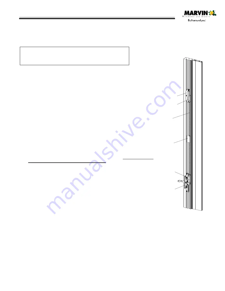
Secondary
Lock
Secondary
Lock Cam
Tie Bar
Support
Block
Primary
Lock Cam
Primary
Lock
Clad units manufactured after January 31, 1994
Wood units manufactured after February 7, 1994
Phillips screwdriver
Hammer
Safety glasses
Stiff putty knife (blade must be sharp and square on end)
Small wood block (approximately 1
″
x 2
″
x 6
″
)
REMOVING SEQUENTIAL LOCKING SYSTEM
1. Unlock and open window.
NOTE: If sequential lock fails to operate and window cannot be opened, complete steps
3 and 4 to remove stops and follow these steps:
A.
Starting near the head jamb carefully insert the putty knife between the lock side stop
and jamb. Gently pry the side stop away from the jamb so the locking mechanism is
visible. Insert the wood block to hold the side stop away from the jamb.
B.
Place the putty knife on the top of the primary cam and tap downward with a hammer
until the cam disengages from the keeper(s). Open window.
2. Remove roto--gear folding handle and cover. Remove screen.
3. Remove hardware cover by inserting putty knife between cover and sill. Gently lift
hardware cover from sill.
4. Remove head jamb stop by inserting putty knife between stop and head jamb. Gently pry
stop downward until it can be removed.
NOTE: If plastic barb stays in kerf during either step, simply push it back into place by hand until
fully seated.
5. Remove the locking side jamb weatherstrip by carefully inserting the putty knife between
the side stop and the weatherstrip, prying the weatherstrip out.
6. Pull back the head jamb and sill weatherstrip to the hinge track, it is not necessary to
completely remove the head jamb or sill weatherstrip.
7. Starting near the head jamb carefully insert the putty knife between the locking side stop
and jamb. Gently pry the stop away from the jamb and remove by twisting the stop toward
the exterior.
8. Observe how the locking hardware is located on the operating jamb and
exactly
which
primary and secondary cam receiving holes the tie bar is using.
NOTE: The tie bar
must
be inserted in the top hole of the primary cam and the center slot of
the secondary cam.
9. Remove the primary and secondary lock assemblies by removing #8 x 1
″
Phillips
panhead wood screws.
TOOLS NEEDED
INSTALLING NEW SEQUENTIAL LOCK ASSEMBLIES
NOTE: The redesigned keeper features a lengthened “throat”
that can easily be seen if an “old” and “new style” keeper are
set side by side.
NOTE: Units manufactured after December 12, 1994 feature an updated
sequential locking system and a date of manufacture stamp (located
under the hardware cover). If locking problems are experienced with a unit
manufactured after this date, contact your Marvin representative.
10. Install the new primary and secondary lock assemblies
using #8 x 1
″
Phillips panhead wood screws. Check
operation.
11.
Remove and install new keeper(s) on sash using
#8 x 1
″
Phillips flathead wood screws.
12.
Install the side stop by inserting the vinyl barb into
weatherstrip kerf. Roll side stop to the interior and seat
barb into jamb kerf.
NOTE: Do not force or hammer side stop into kerf as this may
damage side stop or jamb.
13. Insert head jamb and sill weatherstrip into kerf, followed
by side jamb weatherstrip.
14. Install head jamb stop and hardware cover into kerf.
15. Reinstall folding handle and cover.
16. Check operation by closing and locking window. Unit
should lock easily. If locking problems persist, contact
your Marvin representative.
WARNING: Practice safety! Wear safety glasses
or goggles and appropriate hearing protection.
SWINGING WINDOWS HARDWARE--CASEMASTER
SEQUENTIAL LOCK REPLACEMENT


