background image

USE AND MAINTENANCE 

EN

WEEKEND WARRIOR HD


6042-6049-6062-6073

6042R-6049R-6062R-6073R

Cod. F07011720  

     2020-04

O P E R A T O R ’ S   M A N U A L

MASCHIO GASPARDO S.p.A.

Summary of Contents for WEEKEND WARRIOR 6042

Page 1: ...USE AND MAINTENANCE EN WEEKENDWARRIORHD 6042 6049 6062 6073 6042R 6049R 6062R 6073R Cod F07011720 2020 04 O P E R A T O R S M A N U A L MASCHIO GASPARDO S p A ...

Page 2: ...ng stand 19 Lowering parking stand 19 Levelling attachments side to side 20 Levelling tiller front to rear 20 Adjusting skid shoes 20 TABLE OF CONTENTS Tiller depth adjustment 21 Adjusting levelling board 21 Tilling tips 22 During tilling 22 Replacement parts 22 Service Machine Safely Practice safe maintenance 23 Wear appropriate clothing 23 Stay clear of rotating drivelines 23 Service lubrication...

Page 3: ...s required for safe and satisfactory operation Record the model number and serial number of your equipment in the spaces provided Model Date of Purchase Serial Number see Safety Decal section for location This Safety Alert Simbol indicates a hazard and means ATTENTION BECOME ALERT YOUR SAFETY IS INVOLVED Indicates an imminently hazardous situation that if not avoided will result in death or seriou...

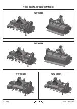
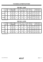
Page 4: ...WW 6042 WW 6049 WW 6042R WW 6049R cod F07011720 4 EN TECHNICAL SPECIFICATIONS ...

Page 5: ... Hitch C 30 5 WW 6042R 42 26 15 35 505 gear slip clutch 540 single speed 215 LTD CAT 1 CAT 1 iMatch Quick Hitch C 30 5 Model Work width inches Implement Code Tractor PTO HP Weight lbs Side Drive PTO shaft protection Input speed rpm Gear box type Rotor rpm Hitch Tines STD Rotor tines Rotor flanges min max WW 6049 49 27 18 35 540 gear slip clutch 540 single speed 215 LTD CAT 1 CAT 1 iMatch Quick Hit...

Page 6: ...WW 6062 WW 6073 WW 6062R WW 6073R cod F07011720 6 EN TECHNICAL SPECIFICATIONS ...

Page 7: ...single speed 215 CAT 1 CAT 1 iMatch Quick Hitch C 48 8 WW6062R 62 35 24 60 690 gear slip clutch 540 single speed 215 CAT 1 CAT 1 iMatch Quick Hitch C 48 8 Model Work width inches Implement Code Tractor PTO HP Weight lbs Side Drive PTO shaft protection Input speed rpm Gear box type Rotor rpm Hitch Tines STD Rotor tines Rotor flanges min max WW6073 73 38 30 60 747 gear slip clutch 540 single speed 2...

Page 8: ...m 26 8 inch cat 1 BUSH Ø 31 5 mm 1 24 in CAT I STD PIN Ø 19 mm 0 748 in BUSH Ø 36 5 mm 1 437 in CAT II STD PIN Ø 28 mm 1 1 in BUSH Ø 36 5 mm 1 437 in CAT II STD PIN Ø 28 mm 1 1 in 825 mm 32 4 inch cat 2 683 mm 26 8 inch cat 1 CAT I STD PIN Ø 19 mm 0 748 in CAT I STD PIN Ø 22 mm 0 866 in CAT I STD PIN Ø 22 mm 0 866 in 683 mm 26 8 inch cat 1 cod F07011720 8 EN TECHNICAL SPECIFICATIONS HITCH WW 6042 ...

Page 9: ... This information must always be quoted whenever assistance or spare parts are needed Machine safety labels 1 WARNING AVOID INJURY FROM ROTATING KNIVES Keep hands feet and clothing away 2 WARNING AVOID INJURY FROM PTO Keep all shields in place Keep hands feet and clothing away Operate only with 540 RPM 3 CAUTION AVOID INJURY Read Operator s Manual Ballast power unit per operator s manual Know loca...

Page 10: ...1 3 2 5 4 4 5 WW 6042 6042R 6049 6049R 6062 6062R 3 2 2 1 1 WW 6073 6073R 3 1 2 2 1 cod F07011720 10 EN MACHINE SAFETY LABELS AND POSITIONS ...

Page 11: ...11720 EN 11 MACHINE LABELS AND POSITIONS 6 Coupling point for lifting indicating the maximun capacity 7 Greasing point Oil fill and level plugs 8 Oil level plug 9 Oil drain plug 10 Oil fill plug 11 Number of revolutions of power takeoff 12 Side Gear decal 13 Reverse decal only for Reverse model 14 Serial number plate 15 Maschio logo big 16 Maschio logo small 17 Model label For Reverse Model For Re...

Page 12: ...e serious injury or death Wear close fitting clothing STOP the engine and be sure PTO driveline is stopped before getting near it Installing tiller on tractor 1 Back tractor into position and align draft links A with draft link brackets on tiller using tractor rockshaft con trol CAUTION Before you work around hitch STOP engine LOCK park brake FIRMLY block tiller on horizontal surface Locate hitch ...

Page 13: ... model Cat I Std 3 Point Hitch 3 Install center link G on tiller and fasten with hitch pin and quicklock pin Q 4 Install PTO shaft to tractor Locate hitch pin in top lift brackets holes B WW 6073 6073R model Cat II Std 3 Point Hitch 2 Fasten each draft link A to draft link brackets with hitch pins and quicklock pins F Locate hitch pin in top hole P WW 6073 6073R model Cat II Std 3 Point Hitch 3 In...

Page 14: ...se tiller 6 Remove spring locking pin K from parking stand 7 Slide parking stand I up along stand bracket J to the bottom hole 8 Fasten with spring locking pin K 9 Level tiller See Leveling Tiller in the Operating Tiller section 10 Adjust sway chains on tractor lower draft arms to minimize side way PTO shaft The PTO shaft supplied with the machine is of standard length When the PTO shaft is fully ...

Page 15: ...y remembering to unscrew one turn at a time If the clutch maintains a temperature of about 104 122 degree Fahrenheit during work this means that it has been correctly regulated Torque Table Torque Setting Friction clutches are equipped with special Belleville springs designed to apply pressure that varies with the amount of compression The table below set out thickness and compression h measured a...

Page 16: ...ht position E CAUTION Before you work around hitch STOP engine LOCK park brake FIRMLY block tiller on horizontal surface INSTALLING Park vehicle safely Stop vehicle on a level surface not on a slope Disengage PTO Engage the park brake STOP the engine Remove the key Before you leave the operator s seat wait for engine and all moving parts to STOP Stay clear of rotating drivelines Entanglement in ro...

Page 17: ...tch pin E from center link F NOTE Put quik lock pins and hitch pins back into brackets on tiller for storage 6 Remove draft links G from draft link brackets H by removing quicklock pins I and hitch pins L NOTE Put quik lock pins and hitch pins back into brackets on tiller for storage 7 Drive tractor forward slowly Removing tiller with Quick Coupler 1 Raise tiller 2 Put parking stand A in the DOWN ...

Page 18: ...hicle Riders are subject to injury such as being thrown off Riders may also obstruct the op erator s view resulting in the machine being operated in an unsafe manner DO NOT let children or an untrained person operate machine DO NOT wear radio or music headphones while op erating the machine Safe operation requires your full attention DO NOT operate the tractor and tiller when you are tired or ill ...

Page 19: ...er bracket 4 Fasten with spring locking pin C OPERATING CAUTION Before you work around hitch STOP engine LOCK park brake FIRMLY block tiller on horizontal surface Wear appropriate clothing Wear close fitting clothing and safely equipment appropriate for the job Loud noise can cause impairment or loss of hearing wear a suitable protective device such as earplugs Stay clear of rotating drivelines En...

Page 20: ... engine d Loosen jam nut A Shorten the center link B to lower the front of the tiller Lengthen the center link B to raise the front of the tiller e Tighten jam nut CAUTION Before you work around hitch STOP engine LOCK park brake FIRMLY block tiller on horizontal surface Adjusting skid shoes Before adjusting skid shoes lift tiller place tiller on top of two wooden blocks underneath tiller rotor see...

Page 21: ... ground C Tilled soil D will be fine and level Tractor speed will determine size of clods E 3 Raise leveling board C Tilled soil D will be coarse and rough Tractor speed will determine size of clods E Leveling board can be adjusted by the chain OPERATING Tiller depth adjustment SKID HOLE POSITION DEPTH VALUE T P 0 Q 1 R 2 S 2 8 SKID HOLE POSITION DEPTH VALUE T P 1 Q 2 R 2 9 S 3 6 For WW6062 WW6062...

Page 22: ...ile the tractor is turning DO NOT back up or make sharp turn with tiller in ground Move PTO switch lever to ON when tiller is out of the ground Move tractor forward and lower tiller into the ground When you till hard ground or sod till at a shallow depth on first pass Increase depth on each pass When tilling on a hillside Work up the the slope if possible If lateral work cannot be avoided work fro...

Page 23: ...s that must be raised for maintenance Keep all parts in good condition and properly installed Fix damage immediately Replace worn or broken parts Remove any buildup of grease oil or debris Unauthorized modifications to the machine may impair its function and safety Wear appropriate clothing Wear close fitting clothing and safely equipment appropriate for the job Loud noise can cause impairment or ...

Page 24: ...of the oil in the gearbox or in the reduc tion unit D and top off to the level mark on the rod as necessary Side transmission gears check the level of the oil in the side casing of the transmission unit unscrewing the level plug F and checking that oil flows out Add oil through the fill plug E if necessary It should flow from the level plug To complete drain the oil from side gears tilt the machin...

Page 25: ...r gear box and side transmission It is advisable to use GR MU EP 2 GREASE or equivalent for all greasing points Bolts tightening torques settings given in Nm lb ft Fine pitch screws CLASS 6 6 8 8 10 9 12 9 M8 x 1 15 11 26 19 36 26 5 44 32 5 M10 x 1 25 30 22 52 38 74 54 88 65 M12 x 1 25 51 37 5 91 67 127 94 153 113 M14 x 1 5 81 60 143 105 201 148 241 178 M16 x 1 5 120 88 214 158 301 222 361 266 M18...

Page 26: ...Tines can be changed with the tiller mounted on tractor Make sure you block the tiller before doing any service on the tiller SERVICE Tines Before replacing tines make sure the tiller is firmly blocked The tines with which the rotary tiller is equipped can work soils of normal conformation Check the degree of wear and condition of the tines each day If the tines should accidentally bend or break d...

Page 27: ...ur Maschio dealer IF CHECK EXCESSIVE TINE WEAR Replace loose or bent tine Replace tine when worn to a point TILLER BUMPING ON GROUND Obstacles entangled in tines Tines incorrectly mounted with no tine spiral effect Tines fitted with blunt edge leading Broken tines INSUFFICIENT DEPTH OBTAINED Adjust depth control skids Insufficient power use lower tractor speed Gear cover on hard soil further passe...

Page 28: ...er section 2 Disconnect tiller from tractor See Removing section 3 Clean tiller and inside of driveline shield 4 Repair or replace badly worn or damaged parts 5 Tighten hardware 6 Lubricate tiller 7 Store tiller in a dry place on a hard level surface with the parking stand in the LOWERED position 8 If you store tiller outside put a waterproof cover on it Removing tiller from storage 1 Install till...

Page 29: ...cod F07011720 EN 29 ...

Page 30: ...emble them Installing draft link brackets PHASE 2 operation 2 4 Put each link brackets O and P on tool bar and fasten bolts and nuts Q R Do not tighten bolts and nuts at this time 5 Measure distance between draft link brackets O For the correct measurement of the brackets cen tered with gearbox see the table on Page 8 6 Tighten lock bolts Q and nuts R to secure draft link brackets to tool bar Fine...

Page 31: ...PHASE 1 PHASE 2 D B C A H F I E G OPERATION 3 OPERATION 4 OPERATION 4 M L OPERATION 1 N OPERATION 2 P O Q T U V Z Y X W N N W X Y Z S R WW 6042 6042R 6049 6049R 6062 6062R cod F07011720 EN 31 ASSEMBLY ...

Page 32: ...d Adjuster U for Left side and V for Right side along with Plate For Skid Adjuster W to the tiller Adjust the skid shoe to the desired tilling depth See page 20 for more details Make sure holes on plate for skid adjuster W is matching with holes on Rear Protection Skid adjuster U and V 11 Tighten bolts X Y and Z and nuts N to the requested tightening torque Fine Pitch screws M12 x 1 25 Class 10 9 ...

Page 33: ...cod F07011720 EN 33 ...

Page 34: ...Installing draft link brackets PHASE 2 operation 2 4 Put each link brackets O and P on tool bar and fasten bolts and nuts Q R Do not tighten bolts and nuts at this time 5 Measure distance between draft link brackets O For the correct measurement of the brackets cen tered with gearbox see the table on Page 8 6 Tighten lock bolts Q and nuts R to secure draft link brackets to tool bar Fine Pitch scre...

Page 35: ...T OPERATION 4 OPERATION 4 U V Z Y X W N W X Z Y N PHASE 1 D B C A H F I E G OPERATION 3 M L N O Q S OPERATION 2 R P OPERATION 1 PHASE 2 WW 6073 6073R cod F07011720 EN 35 ASSEMBLY ...

Page 36: ...d Adjuster U for Left side and V for Right side along with Plate For Skid Adjuster W to the tiller Adjust the skid shoe to the desired tilling depth See page 20 for more details Make sure holes on plate for skid adjuster W is matching with holes on Rear Protection Skid adjuster U and V 11 Tighten bolts X Y and Z and nuts N to the requested tightening torque Fine Pitch screws M12 x 1 25 Class 10 9 ...

Page 37: ...cod F07011720 EN 37 ...

Page 38: ...ass 10 9 Bolts tightening torques 127 Nm 94 lb ft Installing front safety guards PHASE 2 3 Install the front protections provided for your machine by using U bolts G and nuts H 4 Tighten lock nuts H to to secure front protections to the frame Coarse Pitch screws M10 x 1 5 Class 8 8 Bolts tightening torques 50 Nm 37 lb ft 5 In case you are using a WW6073 6073R tiller with CAT 1 hitches install also...

Page 39: ...IDE GUARD LH SIDE GUARD FRONT SIDE GUARD MOUNTING HOLE POSITION WW 6042 6042R FRONT GUARD ONLY ON RH SIDE WW 6049 6049R ON BOTH SIDES WW 6062 6062R ON BOTH SIDES FRONT GUARD FRONT GUARD WW 6062 6062R WW 6073 6073R WW 6042 6042R WW 6049 6049R PHASE 1 H I G G L H H G M N O P H G H I G cod F07011720 EN 39 PHASE 2 ASSEMBLY ...

Page 40: ...AUTION The clearance to respect between the front protections and the lower connec tions is indicated in the table below Sr No MACHINE MODEL A REMARK mm Inch 1 WW 6042 6042R 22 0 9 CAT I 2 WW 6049 6049R 33 1 3 CAT I 3 WW 6062 6062R 31 1 2 CAT I 4 WW 6073 6073R 41 1 6 CAT I 5 23 0 9 CAT II ...

Page 41: ...cod F07011720 EN 41 ...

Page 42: ...uts at this time 4 Install bolt H washer F and nut G to fix the reverse shield A to the external side Do not tighten bolts and nuts at this time 5 Tighten lock bolts B washers C and nuts D to secure reverse shield A to the frame Fine Pitch screws M10 x 1 25 Class 8 8 Screw tightening torques 52 Nm 38 lb ft 6 Tighten lock bolts E washers F and nuts G to secure reverse shield A to the frame Fine Pit...

Page 43: ...A B C F D G E G H F WW 6042R 6049R 6062R 6073R cod F07011720 EN 43 ASSEMBLY ...

Page 44: ...dications Type model and serial number of the machine These data are punched on the data plate with which every implement is equipped Code number of the required spare part This will be found in the spare parts catalogue Description of the part and required quantity Table number ASSEMBLY SPARE PARTS Means of dispatch If this item is not indicated the Manufacturer while dedicating particular care t...

Page 45: ...cod F07011720 EN 45 ...

Page 46: ...6596400 Fax 1 563 6596404 info maschio us MASCHIO IBERICA S L MASCHIO GASPARDO POLAND MASCHIO GASPARDO UCRAINA GASPARDO MASCHIO TURCHIA MASCHIO GASPARDO CINA MASCHIO GASPARDO INDIA MASCHIO GASPARDO SpA Production Plant Via Mussons 7 33075 Morsano al Tagliamento PN Italy Tel 39 0434 695410 Fax 39 0434 695425 info gaspardo it MASCHIO DEUTSCHLAND GMBH Äußere Nürmberger Straße 5 D 91177 Thalmässing De...

Reviews: