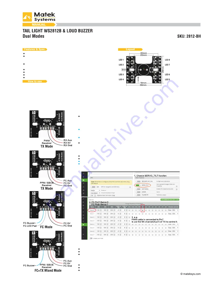
It comes as H Type tail light with 8xWS2812B LEDs & Loud Buzzer. It provides dual control modes, can be controlled by Flight Controller firmware
(Cleanflight, Betaflight,etc.) or Transmiter.
Dual modes: FC control & TX control
TX mode: LED 7 colors (White, Red, Green, Blue, Yellow, Magenta, Cyan)
LED 5 status (Constant light, Slow blink, Fast blink, Voilent blink)
Buzzer: Lost Plane Finder
FC mode: support Naze32, SPRacingF3, etc. with CleanFlight or Betaflight firmware
Input voltage range: 4.5~5.2V DC
Power of TX mode (5V IN ): 1W/0.2A~2W/0.4A
Size & mounting: Pls check the Layout
Weight: 5g
1. Connect Tail Light to 5V power source, such as BEC 5V. Beep once if it is in TX mode.
2. Press the button, scroll through the LED status(Constant light, Slow flash, Fast flash, Voilent flash)
3. Hold the button 2s to enter the setting of LED colors & mode(Be Be Be), then press the button to set it
within LED colors of TX mode (White, Red, Green, Blue, Yellow, Magenta, Cyan) & FC mode (all LED OFF)
4. The LED color(TX mode) or FC mode will be saved if no action within 10 seconds(Be----).
5. Tips:
Default is TX mode with solid & white color LED
If DIN is connected to FC, Pls disconnect it & re-energize the board when changing FC mode to TX mode.
In FC mode, the LED status can’t be changed by pressing the button. But you can hold the button 2s to enter the setting menu.
Pls use the Aux channel with toggle switch of three positions
---Middle position(Value=1400~1600): LED & Buzzer OFF
---Top position(Value=1000~1300): LED ON
---Bottom position(Value=1700~2000): Buzzer ON
Change the LED status: Tune on the LED first(move the switch to value 1000~1300),
then move the switch to middle position & top position within 0.5s. Beep once.
Lost Plane Finder: Move the switch to value=1700~2000, the buzzer & LED light can be triggered.
Tips: The LED status can also be changed by pressing the button
Set the “SERVO REVERSE” in transmiter to change the switch position.
Pls connect the PWM pad to the Aux channel on Flight Controller
Follow the steps to get the Aux in GUI
Then check the setting of “
TX mode for PWM Receiver
”
Tips: Betaflight 3.1.0 or lastest BF firmware. Pls read this Wiki first
https://github.com/betaflight/betaflight/wiki/SERVO_TILT-for-3.1
Example 2: SPRacing F3 Controlling External PWM triggered Buzzer
Set the LED color & status in GUI “LED Strip” according to CleanFlight & BetaFlight guide
Set the buzzer in GUI “Modes”
Tips: set the “Battery voltage monitoring” in GUI to get Low Voltage Alarm.
LED is controlled by TX Mode( 7 colors & 5 status)
Buzzer can be controlled by FC & TX.
Tips: set the “Battery voltage monitoring” in GUI to get Low Voltage Alarm.
TX mode for PPM/SBUS Receiver
FC Mode
FC + TX Mixed Mode
TX mode for PWM Receiver


