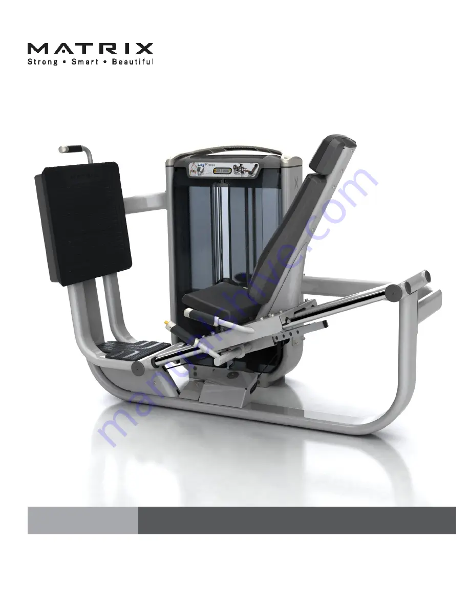
background image

OWNERS MANUAL

ULTRA Single-Station Strength

G7-S70 Leg Press

Summary of Contents for G7-S70

Page 1: ...OWNERS MANUAL ULTRA Single Station Strength G7 S70 Leg Press...

Page 2: ...ting Started Product Specifications 5 Assembly Information 6 Markings 7 Parts List 8 Installation Assembly Value Line Part 1 Weight Stack Frame Assembly 10 Part 2 Cable Assembly 13 Part 3 Seat Assembl...

Page 3: ...t is damaged and or has worn or broken parts Use only replacement parts supplied by your country s local Matrix dealer 2 MAINTAIN LABELS AND NAMEPLATES Do not remove labels for any reason They contain...

Page 4: ...this may result in serious injury 5 NEVER use this equipment for support during stretching as this may result in serious injury 6 Cease exercise if you feel faint or dizzy Obtain a medical exam before...

Page 5: ...5 years Any items not specified 3 years Labor excluding upholstery cables grips 3 years Upholstery cables grips springs 1 year Accessories 6 months MAINTENANCE CHECKLIST ACTION FREQUENCY Clean Upholst...

Page 6: ...ck for this machine is 400 lbs 182 kg To avoid injury to yourself and prevent damage to the frame components be sure to have proper assistance removing the frame pieces from this box Please be sure to...

Page 7: ...7 MARKINGS WARNING LABEL LOCATIONS Hazard warning sticker...

Page 8: ...d Cap Screw 6 12 M10 Flat Washer 22 mm Diameter 14 13 Foot Plate Assembly 1 14 Foot Plate Cover 1 15 M6 Flat Washer 4 16 M6 X 16L Button Head Cap Screw 4 17 M10 X 105L Socket Head Cap Screw 1 18 CAM 1...

Page 9: ...4 M10 X 15L Socket Head Cap Screw 4 35 Head Rest Assembly 1 36 M10 X 75L Button Head Cap Screw 4 37 Back Pad Assmembly 1 38 Left Front Shroud 1 39 Rear Shroud 1 40 Right Front Shroud 1 41 M8 X 60L Soc...

Page 10: ...D DESCRIPTION QUANITY 1 Lower Connecting Tube 1 2 M10 X 30L SHC 4 3 M10 Flat Washer 25 mm Diameter 12 4 Weight Stack 1 5 M10 Nylock Nut 4 6 M10 X 75L SHC 4 7 Upper Connecting Tube 1 Install the user f...

Page 11: ...SHC 2 9 User Frame 1 10 M10 Saddle Washer 2 ASSEMBLY PART 1 USER FRAME ASSEMBLY 9 10 2 3 8 View A Ensure that the frame is level and that all floor pads contact the floor equally Install the frame ha...

Page 12: ...D DESCRIPTION QUANITY 3 M10 Flat Washer 25 mm Diameter 8 5 M10 Nylock Nut 4 6 M10 X 75L SHC 4 11 M10 X 25L SHC 6 12 M10 Flat Washer 22 mm Diameter 6 13 Footplate Assembly 1 ASSEMBLY PART 1 USER FRAME...

Page 13: ...13 STEP 4 FOOT PLATE COVER ASSEMBLY INSTRUCTIONS NOTES ID DESCRIPTION QUANITY 14 Footplate Cover 1 15 M6 Flat Washer 4 16 M6 X 16L BHC 4 ASSEMBLY PART 1 USER FRAME ASSEMBLY 15 16 14...

Page 14: ...ter 2 17 M10 X 105L SHC 1 18 CAM W User Frame Cable Attached 1 ASSEMBLY PART 2 CABLE ASSEMBLY Remove CAM plate Assemble cable into CAM as shown Capture cable end with retaining U clip Using two hex wr...

Page 15: ...15 ASSEMBLY STEP 2 CABLE ASSEMBLY INSTRUCTIONS NOTES PART 2 CABLE ASSEMBLY Remove pulley to route cable inside cable keeper as shown and re torque to 77 N m 57 ft lbs...

Page 16: ...n DO NOT FULLY TIGHTEN 22 21 23 20 19 STEP 1 SEAT SLED ASSEMBLY INSTRUCTIONS NOTES ID DESCRIPTION QUANITY 19 M8 Flat Washer 16 20 M8 Nylock Nut 16 21 Linear Bearing Block 4 22 M8 X 30L SHC 16 23 Seat...

Page 17: ...EMBLY INSTRUCTIONS NOTES PART 3 SEAT ASSEMBLY 24 25 26 27 23 28 Assemble guide rods onto sled as shown ID DESCRIPTION QUANITY 23 Seat Sled 1 24 Rubber Bumper Stop 2 25 Snap Ring 2 26 Disc 45 mm Diamet...

Page 18: ...UCTIONS NOTES PART 3 SEAT ASSEMBLY ID DESCRIPTION QUANITY 25 Snap Ring 2 26 Disc 45 mm Diameter 2 27 Guide Rod Sleeve 2 28 Guide Rod 2 29 End Cap 2 Assemble components as shown Torque linear bearings...

Page 19: ...sembly as shown Tighten to 77 N m 57 ft lbs ASSEMBLY STEP 4 ROM ASSEMBLY INSTRUCTIONS NOTES PART 3 SEAT ASSEMBLY ID DESCRIPTION QUANITY 12 M10 Flat Washer 22 mm Diameter 6 30 ROM Assembly 1 31 M10 X 2...

Page 20: ...S NOTES PART 3 SEAT ASSEMBLY ID DESCRIPTION QUANITY 19 M8 Nylock Nut 1 32 M8 Shoulder Bolt 1 19 32 Remove lower foot plate to gain access to lower pulley and cable end Assemble cable end as show Torqu...

Page 21: ...21 STEP 1 PAD ASSEMBLY INSTRUCTIONS NOTES ID DESCRIPTION QUANITY 33 M10 X 15L SHC 4 34 Pad 1 ASSEMBLY PART 4 PAD ASSEMBLY Orient the pad as shown Tighten to 27 N m 20 ft lbs 34 33...

Page 22: ...P2 BACKPAD HEADPADASSEMBLYINSTRUCTIONS NOTES PART 4 PAD ASSEMBLY ID DESCRIPTION QUANITY 35 Head Rest Assembly 1 36 M10 X 75L BHC 4 37 Back Pad Assembly 1 37 35 36 Install the pad as shown Tighten to 2...

Page 23: ...ROUD ASSEMBLY ASSEMBLY INSTRUCTIONS NOTES PART5 PLASTICSASSEMBLY ID DESCRIPTION QUANITY 38 Left Front Shroud 1 39 Rear Shroud 1 40 Right Front Shroud 1 ASSEMBLY Install the weight stack shrouds as sho...

Page 24: ...4 42 Top Cap 1 ASSEMBLY PART5 PLASTICSASSEMBLY Position top cap so Rep Counter faces the user 41 42 Install the top cap and connect rep counter plug as shown Torque to 17 N m 147 in lbs IMPORTANT NOTI...

Page 25: ...Matrix Fitness 1600 Landmark Drive Cottage Grove WI 53527 matrixfitness com Toll free 866 693 4863 Facsimilie 608 839 8687 ULTRA Leg Press Owners Guide rev 1 2 Copyright 2014 Matrix Fitness...

Reviews: