background image

T 5 x - 0 7   T r e a d m i l l

S e r V i C e   m a N U a l

Summary of Contents for T5X-07

Page 1: ...T 5 x 0 7 T r e a d m i l l S ER V I C E MA N U A l ...

Page 2: ...ubleshooting 8 1 Electrical Diagram 15 8 2 Motor Control Board MCB LED Instructions 18 8 3 MCB Wiring 19 8 4 0140 01A0 01A2 Error Troubleshooting 20 8 5 01A3 Error Troubleshooting 20 8 6 01A8 02B6 02B7 02B8 Error Troubleshooting 21 8 7 01AD Error Troubleshooting 21 8 8 02AD Error Troubleshooting 22 8 9 02B2 Error Troubleshooting 22 8 10 02B9 02BA 02BD Error Troubleshooting 23 8 11 04A0 Error Troub...

Page 3: ...APTER 10 Treadmill specifications and assembly guide 10 1 Treadmill Specifications 51 10 2 Fasteners and Assembly Tools 52 10 3 Assembly Instructions 53 10 4 Leveling the Unit 57 10 5 MYE TV Bracket Installation Instructions 58 10 6 PCTV TV Bracket Installation Instructions 62 CHAPTER 11 SOFTWARE UPGRADE INSTRUCTIONS 11 1 Software Upgrade Instructions 66 Table Of Contents ...

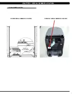
Page 4: ...1 1 1 Serial Number Location Chapter 1 Serial Number Location console serial number location fRAME serial number location ...

Page 5: ...ea with cool temperatures and low humidity Please leave a clear zone behind the treadmill that is at least the width of the treadmill and at least 79 2000 mm long This zone must be clear of any obstruction and provide the user a clear exit path from the machine For ease of access there should be an accessible space on both sides of the treadmill of at least 24 600 mm to allow a user access to the ...

Page 6: ... this product An appliance should never be left unattended when plugged in Unplug from the outlet when not in use and before putting on or taking off parts This product must be used for its intended purpose described in this ser vice manual Do not use other attachments that are not recommended by the manufacturer Attachments may cause injury To prevent electrical shock never drop or insert any obj...

Page 7: ...r box and turn off the breaker s one at a time Once a breaker has been turned off the only thing that should not have power to it is the treadmill No lamps vending machines fans sound systems or any other item should lose power when you perform this test Non looped isolated neutral grounding means that each circuit must have an individual neutral ground connection coming from it and terminating at...

Page 8: ...cro fiber cleaning cloths Vacuum Shop Vac with extendable hose and soft brush attachment Corrosion Block available from Matrix part ZMS4001374 DAILY 1 Wipe down the unit after each use with a mild dish soap and water mixture NOTE Spray the soap water mixture onto the cloth NEVER spray directly onto the equipment We recommend that you do NOT allow customers to use spray bottles to clean the equipme...

Page 9: ... free 2 Check the emergency stop button and cord for proper operation 3 Check the power cord for damage and make sure that the power cord retainer is installed and securely fastened MONTHLY MAINTENANCE ITEMS 1 Check the alignment of the running belt see Section 3 5 2 Check the tension of the running belt see Section 3 5 NOTE If there is any damage to the running belt or deck replace with new If yo...

Page 10: ...treadmill is on This will prevent over tightening of one side STEP 2 The belt should have equal distance on either side between the frame If the belt is touching one side do not start the treadmill Turn the bolts counter clockwise approximately one full turn on each side Manually center the belt by pushing the belt from side to side Tighten the bolts the same amount as when the user loosened them ...

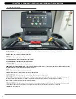
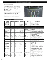
Page 11: ...nds workout and shows workout summary data PAUSE Pauses workout Pause duration can be set in Manager Mode NUMBER KEYPAD Workout data input for workout setup Speed adjustment during workout COOL DOWN Puts treadmill into Cool Down mode Cool Down time is dependent on the length of the workout Workouts 19 minutes and shorter will have a cool down length of 2 minutes Workouts 20 minutes and longer will...

Page 12: ...mation will briefly explain the workouts and how to program the treadmill for each workout selection ROLLING HILLS WORKOUT OPERATION Rolling Hills is a level based workout that automatically adjusts the incline value to simulate walking or running up hills 1 Choose ROLLING HILLS by selecting the rolling hills workout button and press ENTER 2 Enter the desired intensity using the ARROW KEYS or the ...

Page 13: ...ncline STAGE 1 At the 3 minute mark the treadmill will gradually increase speed to 4 5 mph 7 2 kph The actual test begins at 4 5 mph 7 2 kph STAGE 2 After one minute the treadmill incline will increase to 2 STAGE 3 After one minute the treadmill speed increases to 5 0 mph 8 0 kph STAGES 4 THROUGH 11 After every odd minute the treadmill incline will increase by 2 After every even minute the treadmi...

Page 14: ... 46 8 43 9 41 0 36 8 EXCEL LENT 44 2 41 0 39 5 35 2 41 0 38 6 36 3 32 3 GOOD 38 1 36 7 33 8 30 9 36 7 34 6 32 3 29 4 FAIR 35 2 33 8 30 9 28 2 33 8 32 3 29 5 26 9 POOR 32 3 30 5 28 3 25 5 30 6 28 7 26 5 24 3 VERY POOR 28 3 26 5 25 1 22 3 25 9 25 1 23 5 21 1 The Military Test programs and the Physical Efficiency Battery PEB provide workouts of a preset distance These distances are established by the...

Page 15: ...editable TO RESET Press and hold INCLINE DOWN and SPEED DOWN for 3 5 seconds software N A N A N A N A Software Version not editable start speed 0 5 MPH 0 8 KPH 0 5 MPH 0 8 KPH 1 4 MPH 2 3 KPH MPH KPH Controls the starting speed for all programs does not affect minimum speeds maximum speed 12 MPH 20 KPH 2 0 MPH 3 2 KPH 12 MPH 20 KPH MPH KPH Controls the maximum speed for all programs default channe...

Page 16: ...d to enter the serial number First Layer PPPPP V PPPPP is the product name V is the version If the version is A just leave this blank Second Layer YY MM nnnnn YY is the year 11 12 MM is the month e g 08 09 10 nnnnn is the actual serial number Use the UP DOWN LEVEL keys to navigate the layers and the number keys to input the serial number The product name is dependent on the Machine Type setting Fo...

Page 17: ...em Date Data Displays the current time Service 7 Export and Import Parameter Export parameter Export all parameter to USB Import parameter 1 Import parameters to console without accumulated distance and time and serial number Import parameter 2 Import parameters to console Include accumulated distance and time and serial number 1 To enter Service Mode hold the INCLINE DOWN and SPEED DOWN keys for ...

Page 18: ...15 8 1 Electrical Diagram Chapter 8 Troubleshooting ...

Page 19: ...16 8 1 Electrical Diagrams Digital Communication Wire Chapter 8 Troubleshooting UCB Little Board Wire ...

Page 20: ...17 8 1 Electrical Diagrams Hand Pulse Sensor Wire Hand Pulse Wire Chapter 8 Troubleshooting ...

Page 21: ...ing Normal Light MCU Fault Off MSU No Power DOWN DSP5 Indicates if the console is commanding elevation down Light Normal Off No command from console received by the elevation motor UP DSP6 Indicates if the console is commanding elevation up Light Normal Off No command from console received by the elevation motor 12V DSP4 Indicates if the console voltage supply is present Light Normal Off 12 Volts ...

Page 22: ...ring TB1 AC Motor Cable Socket TB2 Input Power Cable Socket J9 Inside Fan Cable Socket J10 Digital Communication Cable Socket J12 Elevation Motor Cable Socket J16 External Fan Cable Socket Chapter 8 Troubleshooting ...

Page 23: ...ER Check the MCB LEDs If LED DOWN Figure A has no light check the console cable connections at the console and MCB Replace the console or cable as needed If LED DOWN has a light replace the incline motor d If the incline motor does not resolve the issue replace the MCB FIGURE A 8 5 01A3 Error Troubleshooting ERROR MESsage 01A3 1 SYMPTOM a Motor is disconnected 2 SOLUTION a Check the connection of ...

Page 24: ...running deck as needed b Replace the MCB 8 7 01AD ERROR TROUBLESHOOTING Error message 0x029F 1 SYMPTOM a Motor over temperature 2 SOLUTION a Check the connection of the motor cable at the MCB Figure A b Use a multi meter to check the motor wire circuit Set the multi meter to Ohms and place both terminals on the blue wires of the motor cable Figure B There should be an Ohm reading of 0 If there is ...

Page 25: ... at the MCB Figure A b If the fans are running correctly replace the MCB FIGURE A 8 9 02B2 error troubleshooting Error Message 02B2 1 SYMPTOM a The emergency circuit on the interface board is active 2 SOLUTION a Check the connection of the safety key emergency stop switch Figure A If the switch is always open or shorted out replace the switch b If the emergency stop does not resolve the issue repl...

Page 26: ...nstant light replace the MCB d If this LED is not lit at all check the power to the MCB FIGURE A 8 11 04A0 Error Troubleshooting Error Message 04A0 1 SYMPTOM a No communication received 2 SOLUTION a If the display is giving an 04A0 error LED DSP2 RS485 should be off Figure A If this light is not on and an 04A0 error is present replace the console b Check the connection of the console communication...

Page 27: ...e if LED 12V DSP4 is lit on the MCB Figure A If the LED 12V is not lit check the incoming AC voltage to the MCB Replace the MCB if all power components are OK and there is AC volts to the MCB c If LED 12V is lit check the connection of the console communication cable If the console communication cable is connected correctly please check the console cable for 12VDC Figure B If there is not power th...

Page 28: ... If the ohm reading is correct your issue is not with the HR grip HR wire portion of the HR system b Perform a continuity test on the treadmill console see Service Bulletin Continuity Test on Matrix Treadmills Verify the HR board ground wire With a multi meter set for ohms place one prong on the HR board ground wire and the other on the console ground screw You should get a resistance reading of 1...

Page 29: ...n from the idler on the drive belt so that it is not slipping Check the rotation of the motor to find any dead spots or a wobble in the motor axle Check the condition of the drive belt Look for any wear or tears Replace as needed c If the amp draw is too high with a user the issue is likely with the deck running belt Inspect the running deck for sticky or worn spots If any wear is seen flip the de...

Page 30: ...olding motor cover to the frame Figure A 3 Pull up on the rear of the motor cover to release the Velcro and remove the motor cover Figure B 4 Remove the 4 screws holding the lower shroud to the frame Figure C 5 Figure D shows a unit with both the motor cover and lower shroud removed Figure A Figure B Figure C Figure D Chapter 9 Part Replacement Guide ...

Page 31: ...hillips screwdriver Figure A 3 Remove both roller adjustment screws using an 8 mm Allen wrench Figure B 4 Remove the roller from the running belt Figures C D 5 Reverse Steps 1 4 to install a new rear roller 6 Tension the running belt as outlined in Section 3 5 Figure A Figure B Figure C Figure D Chapter 9 Part Replacement Guide ...

Page 32: ... Figure A 4 Remove the deck from the running belt Figures B C 5 Reverse Steps 1 4 to install a new running deck NOTE The running deck is waxed on both sides so the opposite side surface may be usable New running deck surfaces must ALWAYS be matched to a new running belt 6 Tension the running belt as outlined in Section 3 5 Figure A Figure B Figure C Chapter 9 Part Replacement Guide ...

Page 33: ...a 5 mm Allen wrench loosen the nut with a 13 mm socket Figure A B 3 For the rear cushion hold the cushion and remove the 13 mm nut Figure C 4 Reverse Steps 1 3 to install new deck cushions 5 Tension the running belt as outlined in Section 3 5 Figure A Figure B Figure C Chapter 9 Part Replacement Guide ...

Page 34: ...way from the drive belt Figures A B 3 Remove the front roller mounting screws using an 8 mm Allen wrench Figures C D 4 Remove the drive belt from the front roller and remove the roller from the running belt Figure E 5 Reverse Steps 1 4 to install a new front roller 6 Tension the running belt as outlined in Section 3 5 Figure A Figure B Figure C Figure D Figure E Chapter 9 Part Replacement Guide ...

Page 35: ...ction 9 3 4 Remove the front roller as outlined in Section 9 5 5 Remove the running belt and replace with a new belt Figures A B NOTE New running belts should ALWAYS be installed on a new deck surface deck should either be flipped or replaced to gain a new surface 6 Tension the running belt as outlined in Section 3 5 Figure A Figure B Chapter 9 Part Replacement Guide ...

Page 36: ...e rail off the back of the treadmill Figures C D 4 Reverse Steps 1 3 to install a new side rail 5 After reinstalling the side rail make sure end cap is on first before tightening screws for proper gap spacing NOTE Be careful not to over tighten the screws or they will poke through the top of the side rail Figure A Figure B Figure D Figure C Chapter 9 Part Replacement Guide ...

Page 37: ...o install a new MCB Be sure to re connect the 5 wires removed from the old MCB in Step 4 Figure C NOTE The speed sensor wire from the motor is no longer used and can be tie strapped to a bracket 7 Auto Calibration must ALWAYS be run after replacing the MCB see Section 3 4 Figure A Figure B Figure C J10 8 pin black connector to the console J16 2 pin white connector to the external fan J12 6 pin whi...

Page 38: ...remove the four motor mounting screws Figure B 6 Lift the motor away from the treadmill Figure C 7 Reverse Steps 1 6 to install a new motor NOTE When reinstalling the motor make sure the red vibration pad is in place Figure D NOTE The wire from the speed sensor on the motor is no longer used and can be tie strapped to the MCB bracket 8 Auto Calibration must ALWAYS be run when installing a new moto...

Page 39: ...in Section 9 5 3 Remove the front roller screw on the drive belt side and loosen the screw on the opposite side Figure A 4 Lift the roller and remove the old drive belt Figure B 5 After installing a new belt check it for correct alignment to the motor pulley before setting the tensioner in place Figure A Figure B Chapter 9 Part Replacement Guide ...

Page 40: ... the machine 2 Lift the treadmill and support it so that the front wheels are off the floor or the unit may be tipped on its side Figure A 3 Remove the clip from the pin attaching the incline motor to the rack Figure B C Figure A Figure B Figure C Chapter 9 Part Replacement Guide ...

Page 41: ...m the incline motor Figure E 6 Lift the incline motor away from the treadmill Figure F 7 Reverse Steps 1 6 to install a new incline motor NOTE When installing the new incline motor make sure to replace the white washers at the top and bottom Figure G 8 Auto Calibration must ALWAYS be run after replacing the incline motor see Section 3 4 Chapter 9 Part Replacement Guide ...

Page 42: ... B 4 Remove the six 6 mm screws from underneath the console There are arrows stamped in the plastic at the proper openings Figure C 5 Move the console away from the console frame Figure D 6 Reverse Steps 1 5 to install a new console 7 Auto Calibration must ALWAYS be run after replacing the console see Section 3 4 Figure A Figure B Chapter 9 Part Replacement Guide Figure c Figure d ...

Page 43: ...ht side of the treadmill Figure A 4 Use a 6 mm Allen wrench to remove one screw and take off the plastic hand rail Figure B Figure A Figure B Figure F Figure G 5 Remove the 5 Phillips screws and remove the right side upper plastic cover Figures C D E 6 Cut the wire ties and begin to un thread the console cable Figures F G Figure C Figure D Figure E Chapter 9 Part Replacement Guide ...

Page 44: ... Lift the frame from the mast arms and set it aside Figure I 9 Use a 6 mm Allen wrench to remove the lower mast arm mounting screws Figure J 10 Pull the mast arm from the side of the machine Figure K 11 Reverse Steps 1 10 to install a new console mast NOTE If replacing the right side mast arm the console cable must be threaded through it prior to it being mounted to the frame Chapter 9 Part Replac...

Page 45: ... 9 12 3 Take off the cup holder from the right side of the treadmill Figure A 4 Use a 6 mm Allen wrench to remove one screw and take off the plastic hand rail Figure B 5 Remove the 5 Phillips screws and remove the right side upper plastic cover Figures C D E Figure A Figure B Figure C Figure D Figure E Chapter 9 Part Replacement Guide ...

Page 46: ...n thread the wire harness Figures F G 7 Remove the spiral protective wrap from the top and bottom portions of the wire harness Figures H I Figure F Figure G Figure H Figure I 9 14 CONSOLE CABLE REPLACEMENT Chapter 9 Part Replacement Guide ...

Page 47: ... cable at the motor tray 3 connections total Figures L M show 2 of these connections the 3rd is the coax cable 11 Attach the new console cable to the pulling wire and gently pull the new cable up through the machine NOTE Once the wire is in place reinstall the spiral wrap and wire ties 12 Reverse Steps 1 7 to finish installing a new console cable 13 Auto Calibration must ALWAYS be run after the in...

Page 48: ...illips screwdriver from the underside of the bar 3 Once the screws are removed lift the part carefully and disconnect any wire connections 4 Replace parts as needed on handle bar including the Quick Start Key and the Heart Rate Grip Plates Figures A F Figure A Figure B Figure C Figure D Figure E Figure F Chapter 9 Part Replacement Guide ...

Page 49: ...igure B 5 Use a Phillips screwdriver to remove two screws one from each side of the mounting bracket Figure C 6 Turn the bracket and use a straight screwdriver or pliers to compress each end of the switch and release it from the bracket Figures D E 7 Reverse Steps 1 6 to install a new emergency stop switch NOTE Make sure the new switch has the same orientation as the old one when installing and th...

Page 50: ...re A 4 Disconnect the wires from each side of the Heart Rate Board Figure B 5 Use a Phillips screwdriver to remove two screws one from each side of the Heart Rate Board mounting bracket Figure C 6 Reverse Steps 1 5 to install a new heart rate board NOTE Be sure to fully seat the wires on the new heart rate board and test the grips after the console is reinstalled Figure A Figure B Figure C Chapter...

Page 51: ...e a Phillips screwdriver to remove the two screws holding the blower motor in place Figure B 5 Carefully separate the blower motor from the duct and remove it Figure C 6 Unplug the wire connections from the main circuit board to completely split the front and rear sections Figure D 7 Reverse Steps 1 6 to install a new blower motor NOTE Be sure to test the blower motor once the console is reinstall...

Page 52: ...Section 9 12 3 Remove the back cover of the console Figure A 4 Unplug and remove the faulty overlay Figure B 5 Clean the console area with alcohol to remove any left over adhesive Figure C 6 Remove the protective film over the display window of the overlay Figure D 7 Peel part of the protective film from the back of the overlay Figure E Figure A Figure B 9 19 overlay replacement Figure C Figure D ...

Page 53: ...ay to keep it in place then remove the protective film Figure H I 11 Once the overlay is in the correct position press down on the overlay with a cloth to adhere it to the console plastic Figure J 12 Use the same procedure to replace any additional faulty overlays NOTE Overlays can not be reused 9 19 Overlay replacement continued Figure G Figure H Figure I FIgure J Chapter 9 Part Replacement Guide...

Page 54: ... HEART RATE METS WATTS STATIC PROFILE DISPLAY USER DEFINED MULTI LANGUAGE DISPLAY YES ENGLISH GERMAN FRENCH ITALIAN SPANISH DUTCH PORTUGUESE JAPANESE SWEDISH FINNISH WORKOUTS MANUAL ROLLING HILLS FAT BURN 5K TARGET HR GERKIN PROTOCOL ARMY PFT NAVY PRT MARINE PFT AIR FORCE PRT PHYSICAL EFFICIENCY BATTERY PEB WFI PROTOCOL CSAFE FITLINXX READY YES NETPULSE READY YES ON THE FLY PROGRAM CHANGE YES FIT ...

Page 55: ... 1 25P x 75 mm 4 White 14 0000086571 Flat Washer 6 2 x 12 x 1 6T 6 White 17 004539 AD Socket Head Cap Screw M8 x 1 25P x 25mm 2 Blue 19 0000088905 Spacer 6 2 x 12 0 x 1 6 2 Blue 15 004859 AC Button Socket Head Cap Screw M8 x 1 25 x 20 mm 6 Red 14 0000086571 Flat Washer 6 2 x 12 x 1 6T 6 Red 13 020072 00 Socket Head Cap Screw M8 x 1 25 x 60mm 4 Yellow 16 062769 00 Socket Head Cap Screw M8 x 1 25 x ...

Page 56: ...63 to report any missing items ASSEMBLY INSTRUCTIONS Please make sure that the power cord is not plugged into the wall outlet while completing the following procedure To ensure correct assembly of the treadmill carefully read and follow these steps Remove the motor cover s and set aside The motor cover s need to be removed to gain access to the motor compartment so that wire harness connections ca...

Page 57: ...item 11 socket head cap screw Assembly Tip It is much easier to accomplish this task if the console base is left inside its shipping container Open Blue Assembly Bag Slide the urethane arms over the steel tubes on the console base Fasten the urethane arms to the steel tubes using item 17 socket head cap screw and item 19 spacer Step 3 Step 4 Chapter 10 Treadmill Specifications and Assembly Guide ...

Page 58: ...All holes applicable to the assembly step can be noted by the embossed arrow next to the hole See pages 69 70 for detailed instructions on wire connections Step 5 Step 6 Chapter 10 TREADMILL SPECIFICATIONS AND ASSEMBLY GUIDE Open Red Assembly Bag Assemble the console base to the console masts using item 15 button head cap screw and item 14 flat washer Be sure to route the console cables down the c...

Page 59: ...over s and power the treadmill on The power button is located next to the power cord inlet Assembly COMPLETE Assembly is complete the running belt should be adjusted as needed and the auto calibration sequence must now be run as outlined in Sections 3 4 and 3 5 Also level the unit as outlined in Section 10 4 Step 7 ...

Page 60: ...ling shim provided on the underside of the treadmill The shim can be found mounted on the underside of the right hand side rail Remove the rear foot on the side of the treadmill that is resting low Install the shim as shown above and return the rear foot When installing the optional rear leveling foot accessory remove the existing rear foot Replace with new leveling foot and fasten to the frame us...

Page 61: ...d PCTV use the same bracket kit which means that there will be unused wiring depending on which type of TV is being installed 1 Remove the 4 screws holding the console back cover to the front and remove the console back cover Figures A B 2 Use a razor to remove the heart rate overlay from the lower portion of the console Figure C 3 Clean the console area with alcohol to remove any left over adhesi...

Page 62: ... to the plastic and keypad Figure I 9 Plug the keypad ribbon cable into the open pins on the UCB Figure J NOTE Make sure that all pins are engaged by the ribbon cable 10 Slide the TV bracket between the console frame and the fan frame Figure K 11 Secure the TV bracket to the console using the 4 socket head screws sent with the bracket kit Figure L Figure G Figure H Figure I Figure J 10 5 MYE TV Br...

Page 63: ... the 4 pin black connector side of the power wire to the TV POWER FOR EP port on the UCB Figure N 14 Plug the side of the controller wire marked TO CONSOLE into the TV port of the CSafe board in the console Figure O 15 Mount the front plate to the MYE TV using 2 screws sent with the TV bracket kit Figure P 16 Mount the TV to the bracket using 4 screws Figure Q NOTE Make sure the tabs of the front ...

Page 64: ... NOTE Make sure to route the wiring through the holes in the back cover so that none of the wiring is pinched Figure W The MATRIX logo portion of the back cover will not be used with a TV bracket 21 Install the TV back cover using 4 screws Figure X 22 A coax cable with a signal strength of 10 Hz should be run to the treadmill and plugged in next to the power cord 23 Enter into Engineering Mode and...

Page 65: ...he TV bracket between the console frame and the fan frame Figure C 3 Secure the TV bracket to the console using the 4 socket head screws sent with the bracket kit Figure D 4 Attach the coax cable from the TV bracket kit to the coax cable coming up the console mast Figure E NOTE There is an adaptor to hook the 2 male coax cable ends together included with the TV bracket kit 5 Attach the 4 pin black...

Page 66: ...er wire 7 Plug the net wire this will have a yellow RJ45 connector on one end into the net wire coming up the console mast Figure H NOTE The net wire is only needed if wired internet will be used 8 Mount the front plate to the MYE TV using 2 screws sent with the TV bracket kit Figure I 9 Plug the coax cable into the port on the PCTV Figure J 10 Plug the TV power wire into the port on the PCTV Figu...

Page 67: ...stic using double sided foam tape 14 Mount the PCTV to the bracket using 4 screws Figure O NOTE Make sure the tabs of the front plate slide behind the console faceplate to create a seamless look Figure P 15 Install the console back cover using the 4 screws removed in Step 1 Figure Q NOTE Make sure to route the wiring through the holes in the back cover so that none of the wiring is pinched Figure ...

Page 68: ...e power switch Figure T 18 Plug a coax cable with a signal strength of 10 Hz into the front of the treadmill near the power cord Figure U 19 if using wired internet plug a net wire into the port on the front of the treadmill near the power switch Figure V 20 Enter into Engineering Mode and set the Audio Source to PCTV 21 A channel scan should be done using the instructions included in the TV owner...

Page 69: ... the USB drive the access should read MATRIX FW UCB Figure B 3 Insert the USB drive into the USB port on the console Figure C 4 When the display is in standard condition press ENTER 9 0 0 1 ENTER on the keypad Press the LEVEL UP or DOWN keys to choose the correct software if there are more than one versions on the USB drive Once the correct software is found press ENTER and the upgrade procedure w...

Page 70: ...67 NOTES ...

Page 71: ...68 MATrix Fitness systems corp 1610 Landmark Drive Cottage Grove wi 53527 USA TOLL FREE 866 693 4863 www matrixfitness com FAX 608 839 1717 REV 01 KO ...

Reviews: