


ME30 infobox connect
18.10.00
infobox connect
1
Application
Device for the acquisition, processing and
indication of alarm and status messages.
Features
• Number of messages: 8, 16, 24 or 40
• Rugged housing intended for front panel
mounting
• Compact, space-saving design
• Uniform faceplate design of all devices
• High degree of immunity
• Opto-decoupled signal input stages
• Output expansion modules (optional)
• Message indication by means of red/green
LEDs or backlight (rear illumination of
message texts)/green LED
• Various voltage ranges for supply and
signalling voltages
• Operating and fault indication
• Internal pushbuttons for message handling
• External inputs with equivalent functions
• Replaceable message text labels
• Message signalling functions according to
DIN 19235
Please note:
This data sheet describes the device that is
capable of signalling 40 messages. For
devices generating 8, 16 or 24 messages, the
number of signal inputs, group messages and
message transmission relay contacts is
reduced accordingly.
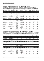
Operating and Display Elements
LED / Backlight
Alarm or status messages
LED “RUN“
Ready for operation
LED “FA“
Device fault
Pushbutton
Horn acknowledgement.
Disconnects the
internal and external
acoustic signal generator.
Pushbutton
Message
acknowledgement
Pushbutton
Delete messages
Pushbutton
Lamp test.
Visual function test of all
message displays using
the colour specified in the
configuration.
Contents
Page
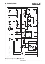
Block Diagrams
2
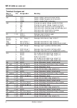
Terminal Assignment
4
Installation and Commissioning
6
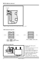
Connections
7
Device Configuration
9
Reset to Factory Settings
11
Boot Loading Functions
11
Software Configuration
11
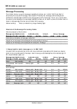
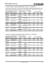
Message Processing
14
Network Message Functions
29
Technical Characteristics
34
Overview of device types
37
Options
38
Accessories
38
infobox connect with 16 messages
T


