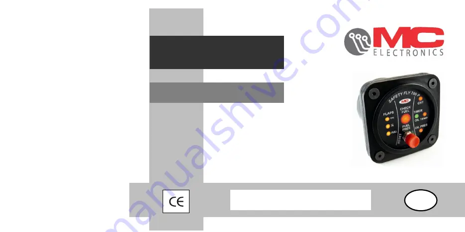
background image


FLYING INSTRUMENT  

FOR ULTRALIGHT AIRCRAFTS 

SAFETY- FLY 700 P


USER MANUAL 


UK


NR.1017.2 MIT


Summary of Contents for SAFETY-FLY 700 P

Page 1: ...FLYING INSTRUMENT FOR ULTRALIGHT AIRCRAFTS SAFETY FLY 700 P USER MANUAL UK NR 1017 2 MIT...

Page 2: ...elettronica it Document num 101700 2 Edition April 2013 MC elettronica S r l is not obliged to give notice of any further modifications to the product The descriptions provided in this manual do not a...

Page 3: ...strument read the manual carefully and refer to it any time you have doubts on how to use the equipment or when you have to carry out maintenance operations Keep the manual on board the aircraft or at...

Page 4: ...g up damage caused when a non MC elettronica equipment which is mechanically and electrically connected to our instruments breaks or does not function properly acts of God lightning floods fire or any...

Page 5: ...indirect charges as a consequence of improper use or inability by the Customer to use the equipment separately and or together with other instruments 1 3 Assistance service Service is available in al...

Page 6: ...6 1 4 General description A B C D M A F G...

Page 7: ...buzzer every 2 minutes to be used to return to position or for various uses such as for example to provide a reminder of closed valves in flight D High motor oil temperature alarm indicator light MANU...

Page 8: ...FETY FLY 700 P where it is most comfortable for the pilot in the picture it is installed on the bottom right hand area of the motor instrument dashboard Fig 1 SAFETY FLY 700 P installed on the motor i...

Page 9: ...CONNECTOR 8 pole connector wire colours Description of connections Orange Input cylinder head temperature CHT Black Input Motor oil temperature Red Input motor pressure temperature Green Input Flaps s...

Page 10: ...d the CHT cylinder head temperature instrument solution A replace the original female terminal with a new one connecting the orange wire to the pre existing one Solution A Fig 2 detail Orange wire con...

Page 11: ...11 Otherwise connect the orange wire to the pre existing one using an ELECTRO TAP connector solution B Solution B Fig 3 detail orange wire connected to the pre existing one by an ELECTRO TAP connector...

Page 12: ...the supplied buzzer in a position that is possibly in front of the pilot observing the polarity as set up on the STC 1017 1 connection board on page 24 25 Fig 4 Buzzer installed on the motor instrumen...

Page 13: ...onnection Black Positive 12 power supply optional Red Positive 12 power supply Green Negative GND optional Yellow Negative GND The Black 12 and yellow GND wires are optional however we suggest connect...

Page 14: ...alarm programming mode and fuel pressure alarm programming mode 2 1 PROGRAMMING MOTOR AND FLAP ALARMS Programming must be carried out when the motor is cold with motor and cylinder head oil temperatu...

Page 15: ...15 Fig 5 Oil pressure bulb with temporarily detached wire PROGRAMMING To start programming the SAFETY FLY 700 P instrument must be off and disconnected from the power detached wire...

Page 16: ...ode i e the pilot will interact manually with the instruments for the movement phase Programming starts with calibrating the cylinder head temperature alarm indicator light CHT followed by the motor o...

Page 17: ...ument is in the required position press the key down until the buzzer beeps 3 times indicating that programming has been carried out correctly Then release the button and continue programming the next...

Page 18: ...D Maximum OIL temperature 4th Flashing red LED ref E Maximum OIL pressure 5th Flashing red LED ref E Maximum OIL pressure 6th 1st Steady orange LED ref G T O FLAP 7th 2nd Steady orange LED ref G 1 2...

Page 19: ...rogram one or more alarms without changing the correct thresholds start the programming phase as described above let the cycle run and only when it is necessary to re program the new threshold press t...

Page 20: ...termine the fixed 3 level operation percentage 7 16 25 To determine the alarm operation percentage the 3 LED flaps G are used and defined as follows led T O 7 led 16 led Full 25 Each LED will remain l...

Page 21: ...Real time if they deviate from the programmed values 3 1 FUEL INDICATOR LIGHT The FUEL indicator light carries out two distinct and different controls a CHECK OPEN VALVES BEFORE TAKE OFF Following the...

Page 22: ...as the buzzer sounds 3 2 MOTOR ALARM OPERATION The CHT cylinder head temperature ref B and oil temperature ref D alarm indicator lights come on when the temperatures exceed the programmed thresholds...

Page 23: ...TION The green indicator light ref C works in two modes a STEADY ON when the motor oil temperature is correct and therefore ready for take off b FLASHING when the timer has been switched on from the r...

Page 24: ...24 Fig 7 example of cylinder head temperature alarm...

Page 25: ...Flaps completely extended 3 LEDs on steady FLAP LEDs TAKE OFF PROCEDURE When the flaps are extended from the T O position one LED on an acoustic timer will come on where for the first 2 minutes at 1 m...

Page 26: ...for more than 3 minutes the buzzer will sound continuously at regular intervals and can be silenced by pressing the red RESET button 3 5 ALARM PANEL ON If the key is left in the dashboard with SAFETY...

Page 27: ...aids navigation however it in no way replaces pilot controls Accordingly the pilot must strictly observe the rules of flight and use of the aircraft as reported in the aircraft manual The pilot must...

Page 28: ...BATTERY 12 Vdc input VERDE GREEN ARANCIO ORANGE NERO BLACK ROSSO RED GIALLO YELLOW VERDE GREEN NERO BLACK ROSSO RED GND ON OFF KEY TEMP CHT OIL TEMP PRESSION FLAPS FUEL PRESSURE TRANSDUCER A FUEL PRES...

Page 29: ...HEME FOR SAFETY FLY 700 R R Do NOT connect when the fuel transducer A is connected to the fuel pressure instrument B R connect to 12 fuel when the fuel transducer A is NOT connected to the fuel instru...

Page 30: ...HNICAL FEATURES Power supply voltage From 9 to 16 Vdc Maximum absorption 150 mA 16 Vdc Operating temperature 20 C 75 C IP Protection degree IP55 front IP45 rear Mechanical resistance 2 g Material Blac...

Page 31: ..._____ _________________________________________________________________ _________________________________________________________________ ______________________________________________________________...

Page 32: ...32 UK...

Reviews: